
Community hub
Adam7 algorithm
View on Wikipedia

Adam7 is an interlacing algorithm for raster images, best known as the interlacing scheme optionally used in PNG images. An Adam7 interlaced image is broken into seven subimages, which are defined by replicating this 8×8 pattern across the full image.
1 6 4 6 2 6 4 6 7 7 7 7 7 7 7 7 5 6 5 6 5 6 5 6 7 7 7 7 7 7 7 7 3 6 4 6 3 6 4 6 7 7 7 7 7 7 7 7 5 6 5 6 5 6 5 6 7 7 7 7 7 7 7 7 |
The subimages are then stored in the image file in numerical order.
Adam7 uses seven passes and operates in both dimensions, compared to only four passes in the vertical dimension used by GIF. This means that an approximation of the entire image can be perceived much more quickly in the early passes, particularly if interpolation algorithms such as bicubic interpolation are used.[1]
History
[edit]Adam7 is named after Adam M. Costello, who suggested the method on February 2, 1995, and after the seven steps involved.
It is a rearrangement[2] of this five-pass scheme[3] that had earlier been proposed by Lee Daniel Crocker:
1 5 3 5 5 4 5 4 3 5 2 5 5 4 5 4 |
Alternative speculative proposals at the time included square spiral interlacing and using Peano curves, but these were rejected as being overcomplicated.
Passes
[edit]The pixels included in each pass, and the total pixels encoded at that point are as follows:
-
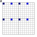
 Pass 1, 1/64 = 1.5625%
 -
 Pass 2, 1/32 = 3.125%
 -
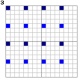 Pass 3, 1/16 = 6.25%
 -
 Pass 4, 1/8 = 12.5%
 -
 Pass 5, 1/4 = 25%
 -
 Pass 6, 1/2 = 50%
 -
 Pass 7, 1/1 = 100%


When rendering, the image will generally be interpolated at earlier stages, rather than just these pixels being rendered.
Related algorithms
[edit]Adam7 is a multiscale model of the data, similar to a discrete wavelet transform with Haar wavelets, though it starts from an 8×8 block, and downsamples the image, rather than decimating (low-pass filtering, then downsampling). It thus offers worse frequency behavior, showing artifacts (pixelation) at the early stages, in return for simpler implementation.
Iteration
[edit]Adam7 arises from iteration of the following pattern:
12 33 |
which may be interpreted as "folding" in the vertical and horizontal dimensions. Similarly, GIF interlacing 1324 can be seen as iteration of the 12 pattern, but only in the vertical direction (12 expands to 1.2. which is filled in as 1324).
Using this 3-pass pattern means the first pass is (1/2)2 = 1/4 (25%) of the image.
Iterating this pattern once yields a 5-pass scheme; after 3 passes this yields
1 . 2 . . . . . 3 . 3 . . . . . |
which is then filled in to:
1 4 2 4 5 5 5 5 3 4 3 4 5 5 5 5 |
In the 5-pass pattern, the first pass (1/4)2 = 1/16 (6.25%) of the image.
Iterating again yields the 7-pass Adam7 scheme, where the first pass (1/8)2 = 1/64 (1.5625%) of the image.
In principle this can be iterated, yielding a 9-pass scheme, an 11-pass scheme, and so forth, or alternatively an adaptive number of passes can be used, as many as the image size will allow (so the first pass consists of a single pixel), as is usual in scale-free multiscale modeling. In the context that PNG was developed (i.e., for the image sizes and connection speeds in question), a 7-pass scheme was seen as sufficient,[why?] and preferable to a simple 5-pass scheme.
References
[edit]- ^ Introduction to PNG - nuwen.net
- ^ Costello, Adam M. (2 Feb 1995). "interlacing revisited: the Adam7 scheme". png-list (Mailing list). Retrieved 2016-04-18.
I rearranged the Lee7 scheme a bit (Lee7 is the obvious extension to Lee's 5-pass scheme), coming up with the Adam7 scheme
- ^ Lane, Tom (1 Feb 1995). "Interlace methods: visual testing". png-list (Mailing list). Retrieved 2016-04-18.
Lee Crocker's 5-pass 2-D interlace proposal
External links
[edit]Adam7 algorithm
View on Grokipedia- Pass 1: Starts at row 0, column 0; increments by 8 for both (1/64 of pixels, forming an 8×8 block grid).
- Pass 2: Starts at row 0, column 4; row increment 8, column increment 8 (adds horizontal details to pass 1).
- Pass 3: Starts at row 4, column 0; row increment 8, column increment 4 (adds details on offset rows for initial columns).
- Pass 4: Starts at row 0, column 2; row increment 4, column increment 4 (transitions to denser spacing).
- Pass 5: Starts at row 2, column 0; row increment 4, column increment 2 (complements pass 4).
- Pass 6: Starts at row 0, column 1; row increment 2, column increment 2 (provides finer detail on remaining even rows).
- Pass 7: Starts at row 1, column 0; row increment 2, column increment 1 (fills all remaining pixels at full resolution).[1]
Introduction
Definition and Purpose
The Adam7 algorithm is a seven-pass interlacing method that divides a raster image into seven subimages based on an 8×8 pattern, facilitating progressive loading and display by transmitting pixels in a sequence that allows for partial rendering.[1] This approach enables decoders to display a coarse approximation of the image early in the transmission process, with subsequent passes refining the detail, which improves the perceived performance of image loading in bandwidth-limited environments such as the web.[1] Specified as an optional feature in the PNG format under ISO/IEC 15948:2004, Adam7 contrasts with non-interlaced PNG images by providing this progressive capability without mandating its use by encoders or decoders beyond basic support.[1] The algorithm generates seven increasingly detailed versions of the image, starting with the first pass that covers only 1/64 of the pixels in a sparse grid, building toward full resolution by the seventh pass.[1]Benefits and Use Cases
The Adam7 algorithm provides significant benefits in scenarios involving progressive image loading, particularly over slow or unreliable network connections. By dividing the image into seven passes that progressively refine the display from a low-resolution preview to full detail, it enables faster visual feedback during transmission. For instance, the first pass delivers a coarse 1/8th-scale approximation of the image, allowing users to immediately recognize content without waiting for the entire file to download. This contrasts with non-interlaced PNGs, which load sequentially and may appear blank until complete, thereby reducing perceived wait times in web browsers and improving user experience.[1] A key advantage is the reduced latency for meaningful image visibility; interlaced PNGs can begin rendering recognizable previews after receiving only a fraction of the data, making them appear sooner than equivalent non-interlaced files of similar size. However, this comes at the cost of increased file size due to the repeated transmission of headers and ancillary chunks across passes, as well as potentially less efficient compression from fragmented scanlines. One example demonstrates an 18% increase for a 152×96 pixel image (from 4,000 bytes non-interlaced to 4,731 bytes interlaced).[1][4] Adam7 has been used for web graphics where progressive loading enhances perceived performance, such as in image galleries or banners that benefit from early previews, though its use has declined in modern contexts due to the size penalty and preference for sequential loading. It also suits thumbnails in progressive image viewers and archival formats like PNG in digital libraries, where partial access to content is valuable for quick scanning. Conversely, it is less ideal for animations (e.g., APNG) or applications prioritizing maximal compression, as the size penalty can outweigh benefits on fast connections. While early passes may introduce minor visual artifacts if interpolation is applied by the viewer to upscale low-resolution data, Adam7 remains simpler and more lightweight than transform-based progressive methods like wavelet compression in JPEG 2000.[1][4][5]Historical Development
Origins in PNG Standardization
The Adam7 algorithm emerged during the development of the Portable Network Graphics (PNG) format in late 1994 and early 1995, as part of collaborative efforts by the PNG working group to establish a royalty-free alternative to the GIF format amid Unisys's enforcement of patents on the LZW compression algorithm used in GIF.[6] The project gained momentum after CompuServe announced its intent to replace GIF with PNG on February 7, 1995, prompting rapid refinement of core features including compression, color support, and progressive rendering capabilities.[7] This work involved contributions from developers associated with libpng, an open-source library for PNG encoding and decoding, which paralleled the specification drafts.[6] The specific Adam7 interlacing scheme was first proposed on February 2, 1995, by Adam M. Costello, as a two-dimensional method to enable faster visual feedback during image loading compared to GIF's one-dimensional approach.[7] It was actively discussed in the png-list mailing list archives throughout 1995, where participants evaluated its balance of progressive display benefits and implementation simplicity within the emerging PNG standard.[7] Adam7 was incorporated into the PNG 1.0 draft by mid-1995, following the release of Draft 9 on March 7, 1995, which froze the core specification after just two months of intense development.[6] The algorithm appeared in the official PNG 1.0 specification, approved as a W3C Recommendation on October 1, 1996, and published as RFC 2083 in March 1997.[8] Subsequent updates, including minor clarifications to interlacing descriptions for better encoder/decoder consistency, were finalized in PNG 1.2 as an International Standard (ISO/IEC 15948:2003) in November 2003.[9]Naming and Key Contributors
The name "Adam7" derives from its primary proposer, Adam M. Costello, combined with the numeral 7 to denote the algorithm's seven distinct passes through the image data.[10] Costello introduced the scheme via an email proposal on February 2, 1995, to the proto-PNG development mailing list, extending earlier ideas for progressive display in raster images.[10] Key contributors to the Adam7 algorithm include Adam M. Costello as the primary architect of the 7-pass method, building on an initial 5-pass interlacing concept proposed by Lee Daniel Crocker during early PNG discussions.[10] Crocker, Costello, and Tom Lane are all credited authors of the official PNG standard, reflecting their pivotal roles in integrating interlacing into the format. Costello's 1995 suggestion specifically aimed to balance progressive detail revelation with computational simplicity, avoiding overly complex schemes while improving upon one-dimensional interlacing like GIF's.[10] This proposal is preserved in archives of the early PNG mailing lists hosted on SourceForge, dating to 1995.[7] Community feedback on the proto-PNG mailing list played a crucial role in Adam7's adoption, where alternatives such as simpler 4- or 5-pass variants were debated and ultimately rejected in favor of the 7-pass design for its superior two-dimensional coverage without excessive overhead.[10] This consensus ensured Adam7 became the standard interlacing method in the PNG specification, ratified in October 1996.Core Algorithm
The 8x8 Interlacing Pattern
The Adam7 algorithm employs a fixed 8×8 interlacing pattern that serves as the foundational grid for mapping pixels to seven progressive passes throughout the image. This pattern is replicated across the entire image, starting from the upper-left corner, to determine the order in which pixels are transmitted and displayed. For images whose dimensions are not multiples of 8, the pattern is applied using flooring to the width and height, ensuring complete coverage without overflow.[11] The 8×8 grid assigns each cell to one of the seven passes, with no cells left unassigned or designated for a pass 0 or 8. Visually, the pattern can be represented as follows, where the numbers indicate the pass number for each position (rows and columns indexed from 1 to 8):1 6 4 6 2 6 4 6
7 7 7 7 7 7 7 7
5 6 5 6 5 6 5 6
7 7 7 7 7 7 7 7
3 6 4 6 3 6 4 6
7 7 7 7 7 7 7 7
5 6 5 6 5 6 5 6
7 7 7 7 7 7 7 7
Pass Structure and Pixel Selection
The Adam7 algorithm traverses the image through seven sequential passes, systematically selecting pixels according to predefined starting positions and increments within the repeating 8x8 interlacing pattern. This structure ensures progressive refinement, where each pass transmits a subset of pixels that interleave with those from prior passes to build a higher-resolution image without overlap or redundancy. The passes are executed in strict order, beginning with the coarsest selection and culminating in the filling of all remaining pixels.[1] Pixel selection in each pass follows a grid-based rule: starting from the specified row and column indices (0-based), the algorithm steps through the image by adding the row distance to the row index and the column distance to the column index repeatedly until the image boundaries are reached. Within each selected row, pixels are processed from left to right. The parameters for the seven passes, which dictate these starting points and step sizes, are detailed in the following table:[1]| Pass | Starting Row | Starting Column | Row Distance | Column Distance |
|---|---|---|---|---|
| 1 | 0 | 0 | 8 | 8 |
| 2 | 0 | 4 | 8 | 8 |
| 3 | 4 | 0 | 8 | 8 |
| 4 | 0 | 2 | 4 | 4 |
| 5 | 2 | 0 | 4 | 2 |
| 6 | 0 | 1 | 2 | 2 |
| 7 | 1 | 0 | 2 | 1 |
Mathematical Details
Coverage per Pass
The Adam7 algorithm divides an image into seven passes, each transmitting a specific subset of pixels based on a repeating 8×8 interlacing pattern, resulting in progressive coverage that starts sparse and becomes denser. In an 8×8 block, Pass 1 covers 1 pixel (1/64 of the block), providing the coarsest approximation at positions like the top-left corner. Pass 2 adds 1 more pixel (additional 1/64, cumulative 2/64 or 1/32), typically at a horizontally offset position in the same coarse rows. Pass 3 contributes 2 pixels (additional 2/64 or 1/32, cumulative 4/64 or 1/16), filling in vertically offset locations to double the detail in both dimensions roughly. Subsequent passes follow this pattern of refinement: Pass 4 adds 4 pixels (additional 4/64 or 1/16, cumulative 8/64 or 1/8); Pass 5 adds 8 pixels (additional 8/64 or 1/8, cumulative 16/64 or 1/4); Pass 6 adds 16 pixels (additional 16/64 or 1/4, cumulative 32/64 or 1/2); and Pass 7 completes the image with the remaining 32 pixels (additional 32/64 or 1/2, cumulative 64/64 or full coverage).[12] This coverage can be summarized in the following table for an 8×8 block, illustrating the incremental pixel counts and fractions:| Pass | Pixels Added | Fraction Added | Cumulative Pixels | Cumulative Fraction |
|---|---|---|---|---|
| 1 | 1 | 1/64 | 1 | 1/64 |
| 2 | 1 | 1/64 | 2 | 1/32 |
| 3 | 2 | 1/32 | 4 | 1/16 |
| 4 | 4 | 1/16 | 8 | 1/8 |
| 5 | 8 | 1/8 | 16 | 1/4 |
| 6 | 16 | 1/4 | 32 | 1/2 |
| 7 | 32 | 1/2 | 64 | 1 |
Pixel Indexing Formulas
The Adam7 algorithm assigns each pixel in an image to one of seven passes based on its coordinates, using a repeating 8×8 pattern that ensures progressive refinement. Pixel positions are typically referenced in 1-based indexing, with (1,1) denoting the top-left corner, as per the PNG specification. To determine the pass, compute the 0-based modular positions $ ix = (x-1) \mod 8 $ and $ iy = (y-1) \mod 8 $, then consult the predefined 8×8 lookup table where rows correspond to $ iy $ (0 to 7) and columns to $ ix $ (0 to 7). The value at table[iy][ix] gives the pass number (1 through 7).[13] The standard Adam7 pattern table is as follows:| iy \ ix | 0 | 1 | 2 | 3 | 4 | 5 | 6 | 7 |
|---|---|---|---|---|---|---|---|---|
| 0 | 1 | 6 | 4 | 6 | 2 | 6 | 4 | 6 |
| 1 | 7 | 7 | 7 | 7 | 7 | 7 | 7 | 7 |
| 2 | 5 | 6 | 5 | 6 | 5 | 6 | 5 | 6 |
| 3 | 7 | 7 | 7 | 7 | 7 | 7 | 7 | 7 |
| 4 | 3 | 6 | 4 | 6 | 3 | 6 | 4 | 6 |
| 5 | 7 | 7 | 7 | 7 | 7 | 7 | 7 | 7 |
| 6 | 5 | 6 | 5 | 6 | 5 | 6 | 5 | 6 |
| 7 | 7 | 7 | 7 | 7 | 7 | 7 | 7 | 7 |
| Pass | Row Start | Row Increment | Column Start | Column Increment |
|---|---|---|---|---|
| 1 | 0 | 8 | 0 | 8 |
| 2 | 0 | 8 | 4 | 8 |
| 3 | 4 | 8 | 0 | 4 |
| 4 | 0 | 4 | 2 | 4 |
| 5 | 2 | 4 | 0 | 2 |
| 6 | 0 | 2 | 1 | 2 |
| 7 | 1 | 2 | 0 | 1 |
function get_pass(x, y):
    for p in 0 to 6:  // passes 1-7
        row_start = [0, 0, 4, 0, 2, 0, 1][p]
        row_inc = [8, 8, 8, 4, 4, 2, 2][p]
        col_start = [0, 4, 0, 2, 0, 1, 0][p]
        col_inc = [8, 8, 4, 4, 2, 2, 1][p]
        if y >= row_start and (y - row_start) % row_inc == 0 and
           x >= col_start and (x - col_start) % col_inc == 0:
            return p + 1
    return -1  // error, no pass