")
Community hub
Recent from talks
Contribute something to knowledge base
Content stats: 0 posts, 0 articles, 1 media, 0 notes
Members stats: 0 subscribers, 0 contributors, 0 moderators, 0 supporters
Subscribers
Supporters
Contributors
Moderators
Hub AI
Starter (engine) AI simulator
(@Starter (engine)_simulator)
Hub AI
Starter (engine) AI simulator
(@Starter (engine)_simulator)
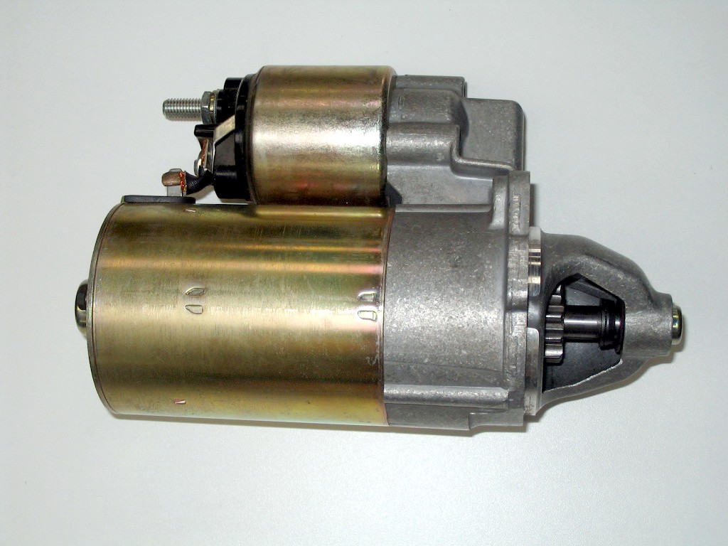
Starter (engine)
A starter (also self-starter, cranking motor, or starter motor) is an apparatus installed in motor vehicles to rotate the crankshaft of an internal combustion engine so as to initiate the engine's combustion cycle. Starters can be electric, pneumatic, or hydraulic. The starter can also be another internal combustion engine in the case, for instance, of very large engines, or diesel engines in agricultural or excavation applications.
Internal combustion engines are feedback systems, which, once started, rely on the inertia from each cycle to initiate the next cycle. In a four-stroke engine, the third stroke releases energy from the fuel, powering the fourth (exhaust) stroke and also the first two (intake, compression) strokes of the next cycle, as well as powering the engine's external load. To start the first cycle at the beginning of any particular session, the first two strokes must be powered in some other way than from the engine itself. The starter motor is used for this purpose and it is not required once the engine starts running and its feedback loop becomes self-sustaining.
Before the advent of the starter motor, engines were started by various methods including wind-up springs, gunpowder cylinders, and human-powered techniques such as a removable crank handle which engaged the front of the crankshaft, pulling on an airplane propeller, or pulling a cord that was wound around an open-face pulley.
The hand-crank method was commonly used to start engines, but it was inconvenient, difficult, and dangerous. The behavior of an engine during starting is not always predictable. The engine can kick back, causing sudden reverse rotation. Many manual starters included a one-directional slip or release provision so that once engine rotation began, the starter would disengage from the engine. In the event of a kickback, the reverse rotation of the engine could suddenly engage the starter, causing the crank to unexpectedly and violently jerk, possibly injuring the operator. For cord-wound starters, a kickback could pull the operator towards the engine or machine, or swing the starter cord and handle at high speed around the starter pulley. Even though cranks had an overrun mechanism, when the engine started, the crank could begin to spin along with the crankshaft and potentially strike the person cranking the engine. Additionally, care had to be taken to retard the spark in order to prevent backfiring; with an advanced spark setting, the engine could kick back (run in reverse), pulling the crank with it, because the overrun safety mechanism works in one direction only.
Although users were advised to cup their fingers and thumb under the crank and pull up, it felt natural for operators to grasp the handle with the fingers on one side, the thumb on the other. Even a simple backfire could result in a broken thumb; it was possible to end up with a broken wrist, a dislocated shoulder or worse. Moreover, increasingly larger engines with higher compression ratios made hand cranking a more physically demanding endeavour.
The first electric starter was installed on an Arnold, an adaptation of the Benz Velo, built in 1896 in East Peckham, England, by electrical engineer H. J. Dowsing.
In 1903, Clyde J. Coleman invented and patented the first electric starter in America U.S. patent 0,745,157.
In 1911, Charles F. Kettering, with Henry M. Leland, of Dayton Engineering Laboratories Company (DELCO), invented and filed U.S. patent 1,150,523 for an electric starter in America. (Kettering had replaced the hand crank on NCR's cash registers with an electric motor five years earlier.)
Recent media
Recent media