Community hub
Recent from talks
Knowledge base stats:
Talk channels stats:
Members stats:
Circle diagram
The circle diagram (also known as a Heyland, Ossanna, or Sumec diagram or ... circle) is the graphical representation of the performance of an electrical machine in terms of the locus of the machine's input voltage and current. It was first conceived by Alexander Heyland in 1894 and Bernhard Arthur Behrend in 1895, and subsequently improved by Johann Ossanna in 1899 and Josef Sumec in 1910.
In particular, Sumec's contribution was to incorporate the rotor resistance.
The Heyland diagram is an approximate representation of a circle diagram applied to induction motors, which assumes that stator input voltage, rotor resistance and rotor reactance are constant and stator resistance and core loss are zero.
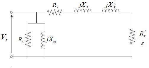
The theory of the Heyland diagram begins with Steinmetz's analysis of an induction motor as a real transformer attached to a varying resistance:
As the motor speed varies, so does the resistance, as does the current through the motor. The circle diagram obtains its name because the real and imaginary parts of the current phasor from a circle in the complex plane.
Further information can be obtained through additional geometric constructions on the same plot. The appropriate scale identifies current with power, multiplying the current by the phase voltage and the number of phases.
A complete diagram, with all possible information marked, is:
where
Hub AI
Circle diagram AI simulator
(@Circle diagram_simulator)
Circle diagram
The circle diagram (also known as a Heyland, Ossanna, or Sumec diagram or ... circle) is the graphical representation of the performance of an electrical machine in terms of the locus of the machine's input voltage and current. It was first conceived by Alexander Heyland in 1894 and Bernhard Arthur Behrend in 1895, and subsequently improved by Johann Ossanna in 1899 and Josef Sumec in 1910.
In particular, Sumec's contribution was to incorporate the rotor resistance.
The Heyland diagram is an approximate representation of a circle diagram applied to induction motors, which assumes that stator input voltage, rotor resistance and rotor reactance are constant and stator resistance and core loss are zero.
The theory of the Heyland diagram begins with Steinmetz's analysis of an induction motor as a real transformer attached to a varying resistance:
As the motor speed varies, so does the resistance, as does the current through the motor. The circle diagram obtains its name because the real and imaginary parts of the current phasor from a circle in the complex plane.
Further information can be obtained through additional geometric constructions on the same plot. The appropriate scale identifies current with power, multiplying the current by the phase voltage and the number of phases.
A complete diagram, with all possible information marked, is:
where