Community hub
Recent from talks
Knowledge base stats:
Talk channels stats:
Members stats:
Fresnel zone
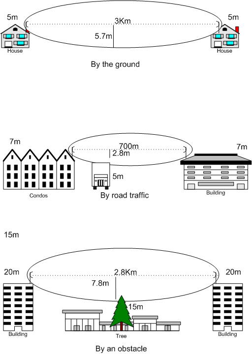
A Fresnel zone (English: /freɪˈnɛl/ fray-NEL), named after physicist Augustin-Jean Fresnel, is one of a series of confocal prolate ellipsoidal regions of space between and around a transmitter and a receiver. The size of the calculated Fresnel zone at any particular distance from the transmitter and receiver predicts whether obstructions or discontinuities along the path will cause significant interference.
The primary wave will travel in a relative straight line from the transmitter to the receiver. Aberrant transmitted radio, sound, or light waves which are transmitted at the same time can follow slightly different paths before reaching a receiver, especially if there are obstructions or deflecting objects between the two. The two waves can arrive at the receiver at slightly different times and the aberrant wave may arrive out of phase with the primary wave due to the different path lengths. Depending on the magnitude of the phase difference between the two waves, the waves can interfere constructively or destructively.
In any wave-propagated transmission between a transmitter and receiver, some amount of the radiated wave propagates off-axis (not on the line-of-sight path between transmitter and receiver). This can then deflect off objects and then radiate to the receiver. However, the direct-path wave and the deflected-path wave may arrive out of phase, leading to destructive interference when the phase difference is half an odd integer () multiple of the period. The n-th Fresnel zone is defined as the locus of points in 3D space such that a 2-segment path from the transmitter to the receiver that deflects off a point on that surface will be between n-1 and n half-wavelengths out of phase with the straight-line path. The boundaries of these zones will be ellipsoids with foci at the transmitter and receiver. In order to ensure limited interference, such transmission paths are designed with a certain clearance distance determined by a Fresnel-zone analysis.

The dependence on the interference on clearance is the cause of the picket-fencing effect when either the radio transmitter or receiver is moving, and the high and low signal strength zones are above and below the receiver's cut-off threshold. The extreme variations of signal strength at the receiver can cause interruptions in the communications link, or even prevent a signal from being received at all.
Fresnel zones are seen in optics, radio communications, electrodynamics, seismology, acoustics, gravitational radiation, and other situations involving the radiation of waves and multipath propagation. Fresnel zone computations are used to anticipate obstacle clearances required when designing highly directive systems such as microwave parabolic antenna systems. Although intuitively, clear line-of-sight between transmitter and receiver may seem to be all that is required for a strong antenna system, but because of the complex nature of radio waves, obstructions within the first Fresnel zone can cause significant weakness, even if those obstructions are not blocking the apparent line-of-sight signal path. For this reason, it is valuable to do a calculation of the size of the 1st, or primary, Fresnel zone for a given antenna system. Doing this will enable the antenna installer to decide if an obstacle, such as a tree, is going to make a significant impact on signal strength. The rule of thumb is that the primary Fresnel zone would ideally be 80% clear of obstacles, but must be at least 60% clear.
Fresnel zones are confocal prolate ellipsoidal shaped regions in space (e.g. 1, 2, 3), centered around the line of the direct transmission path (path AB on the diagram). The first region includes the ellipsoidal space which the direct line-of-sight signal passes through. If a stray component of the transmitted signal bounces off an object within this region and then arrives at the receiving antenna, the phase shift will be something less than a quarter-length wave, or less than a 90º shift (path ACB on the diagram). The effect regarding phase-shift alone will be minimal. Therefore, this bounced signal can potentially result in having a positive impact on the receiver, as it is receiving a stronger signal than it would have without the deflection, and the additional signal will potentially be mostly in-phase. However, the positive attributes of this deflection also depends on the polarization of the signal relative to the object.
The second region surrounds the first region but excludes it. If a reflective object is located in the second region, the stray sine-wave which has bounced from this object and has been captured by the receiver will be shifted more than 90º but less than 270º because of the increased path length, and will potentially be received out-of-phase. Generally this is unfavorable. But again, this depends on polarization. Use of same circular polarization (e.g. right) in both ends, will eliminate odd number of reflections (including one).
The third region surrounds the second region and deflected waves captured by the receiver will have the same effect as a wave in the first region. That is, the sine wave will have shifted more than 270º but less than 450º (ideally it would be a 360º shift) and will therefore arrive at the receiver with the same shift as a signal might arrive from the first region. A wave deflected from this region has the potential to be shifted precisely one wavelength so that it is exactly in sync with the line-of-sight wave when it arrives at the receiving antenna.
Hub AI
Fresnel zone AI simulator
(@Fresnel zone_simulator)
Fresnel zone
A Fresnel zone (English: /freɪˈnɛl/ fray-NEL), named after physicist Augustin-Jean Fresnel, is one of a series of confocal prolate ellipsoidal regions of space between and around a transmitter and a receiver. The size of the calculated Fresnel zone at any particular distance from the transmitter and receiver predicts whether obstructions or discontinuities along the path will cause significant interference.
The primary wave will travel in a relative straight line from the transmitter to the receiver. Aberrant transmitted radio, sound, or light waves which are transmitted at the same time can follow slightly different paths before reaching a receiver, especially if there are obstructions or deflecting objects between the two. The two waves can arrive at the receiver at slightly different times and the aberrant wave may arrive out of phase with the primary wave due to the different path lengths. Depending on the magnitude of the phase difference between the two waves, the waves can interfere constructively or destructively.
In any wave-propagated transmission between a transmitter and receiver, some amount of the radiated wave propagates off-axis (not on the line-of-sight path between transmitter and receiver). This can then deflect off objects and then radiate to the receiver. However, the direct-path wave and the deflected-path wave may arrive out of phase, leading to destructive interference when the phase difference is half an odd integer () multiple of the period. The n-th Fresnel zone is defined as the locus of points in 3D space such that a 2-segment path from the transmitter to the receiver that deflects off a point on that surface will be between n-1 and n half-wavelengths out of phase with the straight-line path. The boundaries of these zones will be ellipsoids with foci at the transmitter and receiver. In order to ensure limited interference, such transmission paths are designed with a certain clearance distance determined by a Fresnel-zone analysis.
The dependence on the interference on clearance is the cause of the picket-fencing effect when either the radio transmitter or receiver is moving, and the high and low signal strength zones are above and below the receiver's cut-off threshold. The extreme variations of signal strength at the receiver can cause interruptions in the communications link, or even prevent a signal from being received at all.
Fresnel zones are seen in optics, radio communications, electrodynamics, seismology, acoustics, gravitational radiation, and other situations involving the radiation of waves and multipath propagation. Fresnel zone computations are used to anticipate obstacle clearances required when designing highly directive systems such as microwave parabolic antenna systems. Although intuitively, clear line-of-sight between transmitter and receiver may seem to be all that is required for a strong antenna system, but because of the complex nature of radio waves, obstructions within the first Fresnel zone can cause significant weakness, even if those obstructions are not blocking the apparent line-of-sight signal path. For this reason, it is valuable to do a calculation of the size of the 1st, or primary, Fresnel zone for a given antenna system. Doing this will enable the antenna installer to decide if an obstacle, such as a tree, is going to make a significant impact on signal strength. The rule of thumb is that the primary Fresnel zone would ideally be 80% clear of obstacles, but must be at least 60% clear.
Fresnel zones are confocal prolate ellipsoidal shaped regions in space (e.g. 1, 2, 3), centered around the line of the direct transmission path (path AB on the diagram). The first region includes the ellipsoidal space which the direct line-of-sight signal passes through. If a stray component of the transmitted signal bounces off an object within this region and then arrives at the receiving antenna, the phase shift will be something less than a quarter-length wave, or less than a 90º shift (path ACB on the diagram). The effect regarding phase-shift alone will be minimal. Therefore, this bounced signal can potentially result in having a positive impact on the receiver, as it is receiving a stronger signal than it would have without the deflection, and the additional signal will potentially be mostly in-phase. However, the positive attributes of this deflection also depends on the polarization of the signal relative to the object.
The second region surrounds the first region but excludes it. If a reflective object is located in the second region, the stray sine-wave which has bounced from this object and has been captured by the receiver will be shifted more than 90º but less than 270º because of the increased path length, and will potentially be received out-of-phase. Generally this is unfavorable. But again, this depends on polarization. Use of same circular polarization (e.g. right) in both ends, will eliminate odd number of reflections (including one).
The third region surrounds the second region and deflected waves captured by the receiver will have the same effect as a wave in the first region. That is, the sine wave will have shifted more than 270º but less than 450º (ideally it would be a 360º shift) and will therefore arrive at the receiver with the same shift as a signal might arrive from the first region. A wave deflected from this region has the potential to be shifted precisely one wavelength so that it is exactly in sync with the line-of-sight wave when it arrives at the receiving antenna.