



Community hub
Recent from talks
Knowledge base stats:
Talk channels stats:
Members stats:
Instrument landing system
In aviation, the instrument landing system (ILS) is a precision radio navigation system that provides short-range guidance to aircraft to allow them to approach a runway at night or in bad weather. In its original form, it allows a pilot, through a cockpit mounted instrument in the aircraft that displays lateral and vertical guidance indications (needles),, to approach until the aircraft is 200 feet (61 m) over the ground, within 1⁄2 mile (800 m) of the runway. At that point the runway should be visible to the pilot; if it is not, they perform a missed approach. Bringing the aircraft this close to the runway dramatically increases the range of weather conditions in which a safe landing can be made. Other versions of the system, or "categories", have further reduced the minimum altitudes, runway visual ranges (RVRs), and transmitter and monitoring configurations designed depending on the normal expected weather patterns and airport safety requirements.
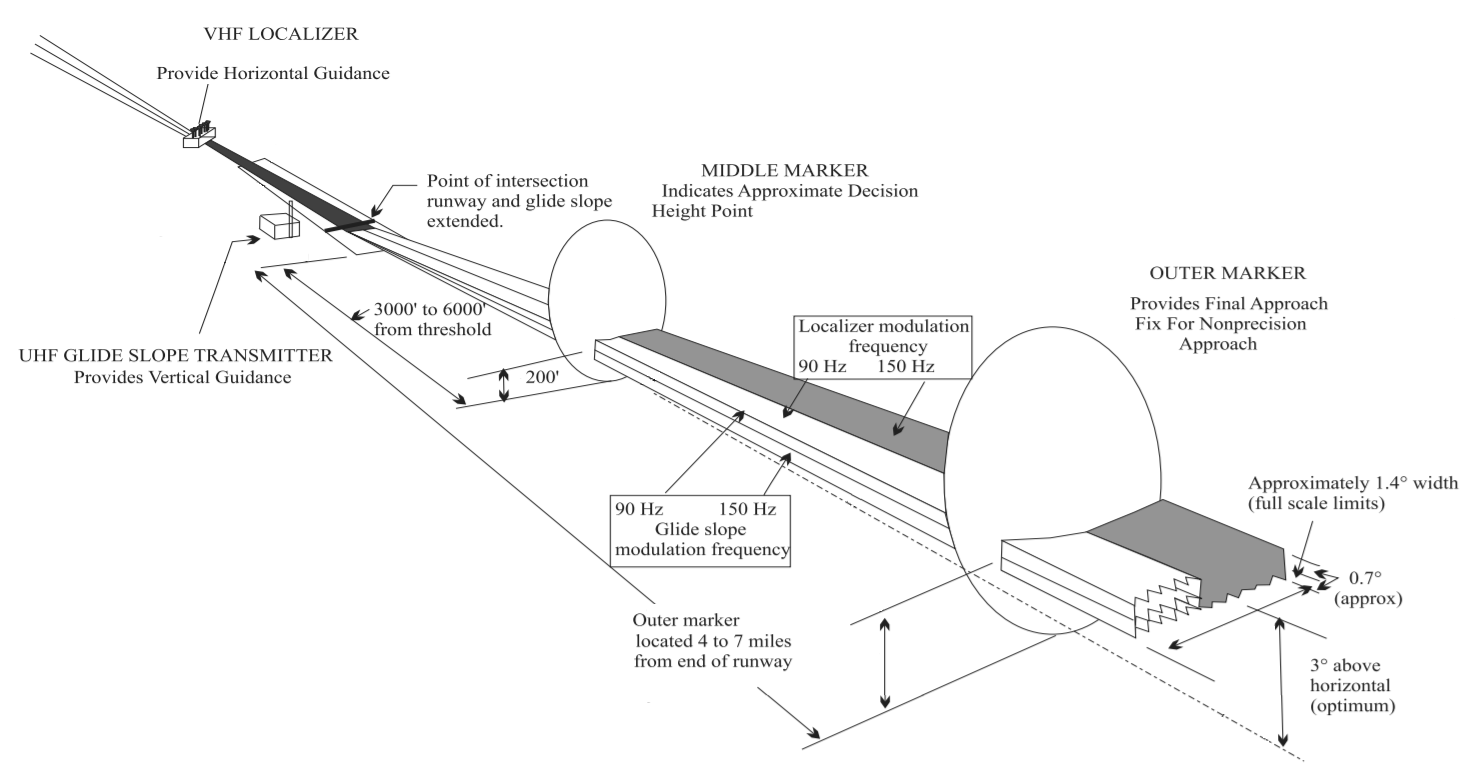
ILS uses two directional radio signals, the localizer (108 to 112 MHz frequency), which provides horizontal guidance, and the glideslope (329.15 to 335 MHz frequency) for vertical guidance. The relationship between the aircraft's position and these signals is displayed on an aircraft instrument, often as additional pointers in the attitude indicator. The pilot attempts to maneuver the aircraft to keep the indicators centered while they approach the runway to the decision height. Optional marker beacon(s) provide distance information as the approach proceeds, including the middle marker (MM), placed close to the position of the (CAT 1) decision height. Markers are largely being phased out and replaced by distance measuring equipment (DME).
To aid the transition from instrument landing to visual, lighting on the runway is often extended towards the decision point using a series of high-intensity lights known as the approach lighting system.
A number of radio-based landing systems were developed between the 1920s and 1940s, notably the Lorenz beam, which was a blind-landing radio navigation system developed by C. Lorenz AG for bad weather landing, which saw relatively wide use in Europe and was also installed on a number of airports on other continents worldwide prior to World War II. Later also the patent for adding vertical guidance like in today's ILS was awarded.
The US-developed SCS-51 system provided a better accuracy for vertical and horizontal guidance. Many sets were installed at airbases in the United Kingdom during World War II. After the formation of the International Civil Aviation Organization (ICAO) in 1947, ILS was selected as the first international standard precision approach system and was published in ICAO Annex 10 in 1950. Further development enabled ILS systems to provide up to CAT-III approaches.
The Precision approach radar (PAR) radar-based ground-controlled approach (GCA), provides the pilot with the necessary horizontal and vertical guidance via VHF- or UHF-voice-communication link. The ATC-controller “talks the pilot down” with the PAR derived guidance information displayed on a special Plan position indicator (PPI) via VHF- or UHF-voice-communication. PAR GCA requires no equipment in the aircraft other than the VHF- or UHF-communication equipment, but requires the pilot and controller to be certified for this use.
The second ICAO standard system for precision approach up to CAT-III is the microwave landing system (MLS) which was also planned for implementation by NATO to replace PAR. Due to the foreseen availability of cost-free GPS service for civil use and later the promise of DGPS, to provide additional correctional data via a VHF-Data-Link to improve reliability up to CAT-I level, most states opted to delay, until today, the implementation of MLS. In addition to the cost for the ground-based MLS system, aircraft operators were forced to equip aircraft, in addition to the MLS-receiver, with a C-Band antenna. The retrofit of a C-Band antenna in the aircraft's fuselage is more time consuming and costly than just retrofitting an MLS-receiver. However more than thousand fixed and transportable MLS systems have been deployed, e.g. in Europe, and more than thousand civil and military aircraft were equipped with MLS equipment and antenna and in use for about a decade.
While the promised availability of free access to GPS signals and later additional global navigation satellite systems (GNSSs) for precision approaches reducing the need for the airport infrastructure compared to a single ILS-system (ILS-LLZ, GP and associated Monitors) looked promising. Ensuring safe 24/7 operation identical to ILS with the same continuity of service, under all operational weather conditions, aircraft orientation during all phases of a flight proved to be impossible without an additional augmentation VHF-Data-Link. One reason is the weak satellite based signals, which unlike much stronger ILS- or MLS- signals, very sensitive even to very weak RFI-, intentional Jamming- or Spoofing signals.
Hub AI
Instrument landing system AI simulator
(@Instrument landing system_simulator)
Instrument landing system
In aviation, the instrument landing system (ILS) is a precision radio navigation system that provides short-range guidance to aircraft to allow them to approach a runway at night or in bad weather. In its original form, it allows a pilot, through a cockpit mounted instrument in the aircraft that displays lateral and vertical guidance indications (needles),, to approach until the aircraft is 200 feet (61 m) over the ground, within 1⁄2 mile (800 m) of the runway. At that point the runway should be visible to the pilot; if it is not, they perform a missed approach. Bringing the aircraft this close to the runway dramatically increases the range of weather conditions in which a safe landing can be made. Other versions of the system, or "categories", have further reduced the minimum altitudes, runway visual ranges (RVRs), and transmitter and monitoring configurations designed depending on the normal expected weather patterns and airport safety requirements.
ILS uses two directional radio signals, the localizer (108 to 112 MHz frequency), which provides horizontal guidance, and the glideslope (329.15 to 335 MHz frequency) for vertical guidance. The relationship between the aircraft's position and these signals is displayed on an aircraft instrument, often as additional pointers in the attitude indicator. The pilot attempts to maneuver the aircraft to keep the indicators centered while they approach the runway to the decision height. Optional marker beacon(s) provide distance information as the approach proceeds, including the middle marker (MM), placed close to the position of the (CAT 1) decision height. Markers are largely being phased out and replaced by distance measuring equipment (DME).
To aid the transition from instrument landing to visual, lighting on the runway is often extended towards the decision point using a series of high-intensity lights known as the approach lighting system.
A number of radio-based landing systems were developed between the 1920s and 1940s, notably the Lorenz beam, which was a blind-landing radio navigation system developed by C. Lorenz AG for bad weather landing, which saw relatively wide use in Europe and was also installed on a number of airports on other continents worldwide prior to World War II. Later also the patent for adding vertical guidance like in today's ILS was awarded.
The US-developed SCS-51 system provided a better accuracy for vertical and horizontal guidance. Many sets were installed at airbases in the United Kingdom during World War II. After the formation of the International Civil Aviation Organization (ICAO) in 1947, ILS was selected as the first international standard precision approach system and was published in ICAO Annex 10 in 1950. Further development enabled ILS systems to provide up to CAT-III approaches.
The Precision approach radar (PAR) radar-based ground-controlled approach (GCA), provides the pilot with the necessary horizontal and vertical guidance via VHF- or UHF-voice-communication link. The ATC-controller “talks the pilot down” with the PAR derived guidance information displayed on a special Plan position indicator (PPI) via VHF- or UHF-voice-communication. PAR GCA requires no equipment in the aircraft other than the VHF- or UHF-communication equipment, but requires the pilot and controller to be certified for this use.
The second ICAO standard system for precision approach up to CAT-III is the microwave landing system (MLS) which was also planned for implementation by NATO to replace PAR. Due to the foreseen availability of cost-free GPS service for civil use and later the promise of DGPS, to provide additional correctional data via a VHF-Data-Link to improve reliability up to CAT-I level, most states opted to delay, until today, the implementation of MLS. In addition to the cost for the ground-based MLS system, aircraft operators were forced to equip aircraft, in addition to the MLS-receiver, with a C-Band antenna. The retrofit of a C-Band antenna in the aircraft's fuselage is more time consuming and costly than just retrofitting an MLS-receiver. However more than thousand fixed and transportable MLS systems have been deployed, e.g. in Europe, and more than thousand civil and military aircraft were equipped with MLS equipment and antenna and in use for about a decade.
While the promised availability of free access to GPS signals and later additional global navigation satellite systems (GNSSs) for precision approaches reducing the need for the airport infrastructure compared to a single ILS-system (ILS-LLZ, GP and associated Monitors) looked promising. Ensuring safe 24/7 operation identical to ILS with the same continuity of service, under all operational weather conditions, aircraft orientation during all phases of a flight proved to be impossible without an additional augmentation VHF-Data-Link. One reason is the weak satellite based signals, which unlike much stronger ILS- or MLS- signals, very sensitive even to very weak RFI-, intentional Jamming- or Spoofing signals.