Hubbry Logo
Attitude indicatorAttitude indicatorMain
Open search
Attitude indicator
Community hub
Attitude indicator
logo
8 pages, 0 posts
0 subscribers
Be the first to start a discussion here.
Attitude indicator
Attitude indicator
from Wikipedia
AI with pitch and roll reference lines (left) and the AI relationship to aircraft orientation (right)

The attitude indicator (AI), also known as the gyro horizon or artificial horizon, is a flight instrument that informs the pilot of the aircraft orientation relative to Earth's horizon, and gives an immediate indication of the smallest orientation change. The miniature aircraft and horizon bar mimic the relationship of the aircraft relative to the actual horizon.[1][2] It is a primary instrument for flight in instrument meteorological conditions.[3][4]

Attitude is always presented to users in the unit degrees (°). However, inner workings such as sensors, data and calculations may use a mix of degrees and radians, as scientists and engineers may prefer to work with radians.

History

[edit]

Before the advent of aviation, artificial horizons were used in celestial navigation. Proposals of such devices based on gyroscopes, or spinning tops, date back to the 1740s,[5] including the work of John Serson.

Another notable development came in 1785, when John Adams, an English mathematician and headmaster of Latymer’s Charity School, was awarded a Silver Medal by the Royal Society for the Encouragement of Arts, Manufactures, and Commerce for his invention of an 'Artificial Horizon to be used on Land'.[6] In his letter and historical account addressed to the Society, Adams detailed how he had acquired a siphon circular spirit level in 1764 and, by 1778, had proposed to the London instrument maker Peter Dollond, a method by which it could be adapted to calculate latitude and longitude.[7]

Later implementations, also known as bubble horizons, were based on bubble levels and attached to a sextant.[8] In the 2010s, remnants of an artificial horizon using liquid mercury were recovered from the wreck of HMS Erebus.[9]

Use

[edit]
AI interior

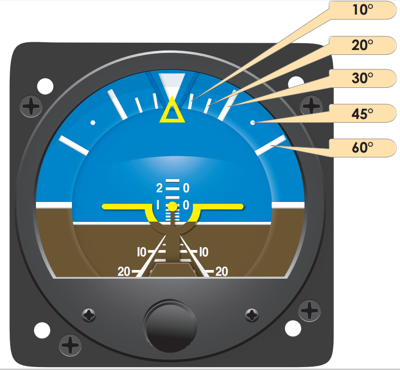
The essential components of the AI include a symbolic miniature aircraft mounted so that it appears to be flying relative to the horizon. An adjustment knob, to account for the pilot's line of vision, moves the aircraft up and down to align it against the horizon bar. The top half of the instrument is blue to represent the sky, while the bottom half is brown to represent the ground. The bank index at the top shows the aircraft angle of bank. Reference lines in the middle indicate the degree of pitch, up or down, relative to the horizon.[2][1]

Most Russian-built aircraft have a somewhat different design. The background display is colored as in a Western instrument, but moves up and down only to indicate pitch. A symbol representing the aircraft (which is fixed in a Western instrument) rolls left or right to indicate bank angle.[10] A proposed hybrid version of the Western and Russian systems would be more intuitive, but has never caught on.[11]

Operation

[edit]
Vacuum system using a vacuum pump
Vacuum system using a venturi

The heart of the AI is a gyroscope (gyro) that spins at high speed, from either an electric motor, or through the action of a stream of air pushing on rotor vanes placed along its periphery. The stream of air is provided by a vacuum system, driven by a vacuum pump, or a venturi. Air passing through the narrowest portion of a venturi has lower air pressure through Bernoulli's principle. The gyro is mounted in a double gimbal, which allows the aircraft to pitch and roll as the gyro stays vertically upright. A self-erecting mechanism, actuated by gravity, counteracts any precession due to bearing friction. It may take a few minutes for the erecting mechanism to bring the gyros to a vertical upright position after the aircraft engine is first powered up.[2][1][12]

Attitude indicators have mechanisms that keep the instrument level with respect to the direction of gravity.[13] The instrument may develop small errors, in pitch or bank during extended periods of acceleration, deceleration, turns, or due to the earth curving underneath the plane on long trips. To start with, they often have slightly more weight in the bottom, so that when the aircraft is resting on the ground they will hang level and therefore they will be level when started. But once they are started, that pendulous weight in the bottom will not pull them level if they are out of level, but instead its pull will cause the gyro to precess. In order to let the gyro very slowly orient itself to the direction of gravity while in operation, the typical vacuum powered gyro has small pendulums on the rotor casing that partially cover air holes. When the gyro is out of level with respect to the direction of gravity, the pendulums will swing in the direction of gravity and either uncover or cover the holes, such that air is allowed or prevented from jetting out of the holes, and thereby applying a small force to orient the gyro towards the direction of gravity. Electric powered gyros may have different mechanisms to achieve a similar effect.[14]

Older AIs were limited in the amount of pitch or roll that they would tolerate. Exceeding these limits would cause the gyro to tumble as the gyro housing contacted the gimbals, causing a precession force. Preventing this required a caging mechanism to lock the gyro if the pitch exceed 60° and the roll exceeded 100°. Modern AIs do not have this limitation and therefore do not require a caging mechanism.[2][1]

Attitude indicators are free from most errors, but depending upon the speed with which the erection system functions, there may be a slight nose-up indication during a rapid acceleration and a nose-down indication during a rapid deceleration. There is also a possibility of a small bank angle and pitch error after a 180° turn. These inherent errors are small and correct themselves within a minute or so after returning to straight-and-level flight.[1]

Flight Director Attitude Indicator

[edit]
Apollo Flight Director Attitude Indicator (left) and Inertial Measurement Unit (IMU) (right)

Attitude indicators are also used on crewed spacecraft and are called Flight Director Attitude Indicators (FDAI), where they indicate the craft's yaw angle (nose left or right), pitch (nose up or down), roll, and orbit relative to a fixed-space inertial reference frame from an Inertial Measurement Unit (IMU).[15] The FDAI can be configured to use known positions relative to Earth or the stars, so that the engineers, scientists and astronauts can communicate the relative position, attitude, and orbit of the craft.[16][17]

Attitude and Heading Reference Systems

[edit]

Attitude and Heading Reference Systems (AHRS) are able to provide three-axis information based on ring laser gyroscopes, that can be shared with multiple devices in the aircraft, such as "glass cockpit" primary flight displays (PFDs). Rather than using a spinning gyroscope, modern AHRS use solid-state electronics, low-cost inertial sensors, rate gyros, and magnetometers.[2]: 8–20 [1]: 5–22 

With most AHRS systems, if an aircraft's AIs have failed there will be a standby AI located in the center of the instrument panel, where other standby basic instruments such as the airspeed indicator and altimeter are also available. These mostly mechanical standby instruments may remain available even if the electronic flight instruments fail, although the standby attitude indicator may be electrically driven and will, after a short time, fail if its electrical power fails.[18]

Attitude Direction Indicator

[edit]
ADI (left) with yellow V steering bars, and an AI integrated with ILS glide slope and localizer indicators (right)

The Attitude Direction Indicator (ADI), or Flight Director Indicator (FDI), is an AI integrated with a Flight Director System (FDS). The ADI incorporates a computer that receives information from the navigation system, such as the AHRS, and processes this information to provide the pilot with a 3-D flight trajectory cue to maintain a desired path. The cue takes the form of V steering bars. The aircraft is represented by a delta symbol and the pilot flies the aircraft so that the delta symbol is placed within the V steering bars.[1]: 5–23, 5–24 

See also

[edit]

References

[edit]
Revisions and contributorsEdit on WikipediaRead on Wikipedia
from Grokipedia
An attitude indicator, also known as an artificial horizon, is a gyroscopic flight instrument that provides pilots with an instantaneous visual indication of an aircraft's pitch and bank orientation relative to the Earth's horizon. It features a miniature superimposed on a horizon bar, allowing for quick interpretation of attitude changes during flight. The instrument operates on the principle of gyroscopic rigidity in space, with a spinning mounted horizontally to maintain a fixed reference to the horizon despite maneuvers. Traditional vacuum- or electrically-powered models display pitch attitudes up to 60° to 70° and angles up to 100° to 110°, though exceeding these limits can cause the display to "tumble" and require resetting. Modern electronic versions, often integrated with attitude and heading reference systems (AHRS), eliminate tumbling risks and provide expanded display ranges for enhanced reliability. Central to instrument flight rules (IFR) operations, the attitude indicator is positioned in the pilot's primary field of view to facilitate precise control, especially in low-visibility conditions, and serves as a critical when substituting for other required instruments like the rate-of-turn indicator. Its development traces back to the late 1920s, when improved gyroscopic designs enabled Jimmy Doolittle's groundbreaking 1929 blind instrument flight—the first takeoff, navigation, and landing without external visual references—paving the way for safe all-weather .

Fundamentals

Definition and Purpose

The attitude indicator, also known as the artificial horizon, is a primary flight instrument that provides a visual representation of an aircraft's pitch and attitude relative to the Earth's horizon. It simulates the natural horizon using a miniature airplane symbol superimposed on a horizon bar, allowing pilots to determine whether the aircraft's nose is pointing up or down (pitch) and whether the wings are level or tilted (). This gyroscopic instrument is mounted to maintain rigidity in space, offering an immediate and realistic depiction of the aircraft's orientation in three dimensions. The primary purpose of the attitude indicator is to enable pilots to maintain spatial orientation during flight, particularly in low-visibility conditions such as clouds, , or night operations where external visual references are unavailable. By providing an artificial horizon, it counters the vestibular system's tendency to produce misleading sensations, preventing that can lead to loss of control or (CFIT) accidents. In (IMC), reliance on the attitude indicator is crucial for safe attitude control, as it overrides false sensory inputs from the and body, allowing pilots to execute precise maneuvers and avoid collisions. For certification in IFR operations, attitude indicators must comply with (FAA) standards outlined in 14 CFR Part 23 for normal category airplanes and Part 25 for transport category airplanes, which mandate gyroscopic pitch and bank indication as part of required under 14 CFR § 91.205.

Basic Components

The attitude indicator comprises several essential components that work together to provide accurate pitch and information. The core element is the , a spinning rotor typically mounted in a horizontal plane, which maintains rigidity in space due to its high rotational speed. This gyro is supported by gimbals, a set of pivoted rings that allow freedom of movement in pitch and roll axes without affecting the gyro's orientation. The display features a horizon bar, attached to the gyro, which represents the Earth's . A fixed miniature symbol, mounted to the instrument case, moves relative to the horizon bar to indicate the aircraft's attitude. A pointer and scale on the periphery show the degree and direction of . An adjustment knob allows the pilot to align the miniature airplane with the horizon bar during straight-and-level flight. The instrument is powered either by a vacuum system, which drives the gyro via suction, or by an in modern variants.

Historical Development

Early Innovations

The attitude indicator, also known as the artificial horizon or gyro horizon, originated from early 20th-century efforts to enable instrument flying in poor visibility conditions. Lawrence B. Sperry, son of inventor Elmer A. Sperry, pioneered key gyroscopic flight instruments during , including a rudimentary artificial horizon demonstrated in 1914 as part of an system that integrated pitch and roll stabilization. This early device used a to maintain a fixed reference plane, addressing the unreliability of visual cues or magnetic compasses, which could mislead pilots during turns due to acceleration-induced errors. Sperry's innovations, tested in 1916 under U.S. Navy auspices, laid the groundwork for independent attitude sensing but were limited by single-axis that suffered from errors and restricted range in dynamic maneuvers. In 1929, the Sperry Gyroscope Company, founded by Elmer A. Sperry, advanced these concepts by developing a practical as part of a "three-element" instrument system comprising the gyro horizon, directional gyro, and sensitive . This system enabled the first fully blind flight on September 24, 1929, when U.S. Army Lt. James H. Doolittle completed a takeoff, , and solely by instruments in a Consolidated NY-2 , marking a pivotal in . The indicator featured a multi-gimbal for improved pitch and roll depiction, overcoming prior accuracy issues with single-axis designs by providing a more stable visual representation of the aircraft's orientation relative to the horizon. A key patent for this gyroscopic horizon indicator, filed in 1929 by the Sperry Gyroscope Company (U.S. Patent 1,939,825, granted 1933), described a device using a spinning rotor to erect and maintain a horizontal reference plane, essential for instrument flight. During , attitude indicators saw widespread adoption in , enhancing operational capabilities in all-weather and night missions. For instance, Sperry gyro horizon indicators, such as the AN5736-1, were integrated into U.S. Army Air Forces bombers like the , where it provided critical attitude data amid the limitations of early venturi-tube-driven gyros that were prone to icing and airflow disruptions. To address these shortcomings, vacuum-driven gyro systems were introduced in the early , replacing venturi aspiration with engine-driven pumps for more reliable rotor spin-up and reduced susceptibility to external air conditions, thereby improving accuracy and uptime in combat environments. These innovations collectively transformed the attitude indicator from an experimental tool into a standard essential by the mid-20th century.

Evolution to Modern Systems

Following , advancements in gyroscopic technology shifted toward electric-powered systems in the , enabling more reliable operation without reliance on pumps common in earlier designs. These electric gyros improved consistency in and military applications by providing stable power sources less susceptible to mechanical wear. Building on early gyro patents from the , such as those by Elmer Sperry, these developments laid the groundwork for integrated attitude sensing. In the 1970s, experiments with ring laser gyroscopes (RLGs) marked a significant leap in precision for attitude indicators. Honeywell's initial production of RLGs for the U.S. Navy in 1966 evolved through the decade, culminating in contracts for military aircraft in the late 1970s and 1980s, where RLGs offered drift rates orders of magnitude lower than mechanical gyros, enhancing long-term accuracy in dynamic flight environments. Regulatory frameworks also evolved to emphasize redundancy, particularly for transport category . The (FAA) mandates under 14 CFR § 25.1303 require a standby attitude indicator independent of the primary system and other , ensuring continued operation in case of failure; this requirement, formalized in the mid-20th century but reinforced through post-accident reviews in the 1990s, addressed vulnerabilities highlighted in incidents involving instrument malfunctions. Key innovations in the 1980s included the integration of flux gate magnetometers with gyro systems for real-time heading correction. These devices, which detect the to slave directional gyros, minimized errors in attitude indicators, as demonstrated in advanced flight control studies where flux valves provided stable long-term heading data complementary to short-term gyro outputs. The saw a transition to solid-state sensors, replacing mechanical gimbals with laser-based and early electronic components that eliminated tumble risks associated with extreme maneuvers. Unlike traditional gyros limited to 60-70° pitch or 100-110° before tumbling, solid-state designs maintained functionality across full attitude ranges, improving safety in aerobatic and high-performance aircraft. By the 2010s and into the 2020s, have driven adoption of compact, cost-effective attitude indicators in and unmanned aerial vehicles (UAVs). gyroscopes and accelerometers, integrated into lightweight units, provide high-resolution pitch and roll data with low power consumption, enabling widespread use in drones for stable flight control and in GA aircraft for affordable upgrades without the bulk of legacy systems.

Operational Principles

Gyroscopic and Inertial Mechanisms

The attitude indicator relies on gyroscopic principles to maintain a stable reference for the aircraft's orientation relative to the horizon. At its core, the exploits the property of rigidity in space, which stems from the conservation of . When a spins rapidly about its axis, its angular momentum vector resists changes in direction due to external torques, effectively holding the spin axis fixed in inertial space while the aircraft moves around it. This rigidity enables the instrument to sense pitch and roll attitudes accurately. However, external , such as those from maneuvers, induce in the —a rotational motion perpendicular to both the and the spin axis. The relationship is governed by the torque-induced precession formula: α=τIω\alpha = \frac{\tau}{I \omega} where α\alpha is the precession , τ\tau is the applied , II is the of the rotor, and ω\omega is the rotor's spin . This precession allows the gimbals to track the 's orientation changes without altering the gyro's inherent stability. Mechanical gyroscopes in traditional attitude indicators feature a spinning rotor, typically driven by vacuum or electric power, that rotates at speeds exceeding 10,000 RPM to achieve sufficient for rigidity. The rotor is mounted within a system—usually a double or universal gimbal configuration—that provides three degrees of rotational , allowing 360° movement in pitch and roll axes while minimizing the risk of , where axes align and lose a degree of . This setup ensures the gyro remains oriented independently of the aircraft's attitude, serving as an inertial reference. Despite these principles, errors arise from apparent precession caused by internal friction in bearings and gimbals, which introduces gradual drift from the true inertial reference over time. To counteract this, self-erecting mechanisms employ pendulous vanes—gravity-sensitive weights attached to the gyro housing—that detect tilts and apply corrective torques via air jets or electric signals, inducing controlled to realign the spin axis vertically. These systems restore accuracy within minutes using automatic erection, with manual caging used only after excessive attitudes or for pre-flight setup. In modern implementations, attitude indicators integrate with inertial navigation through basic strapdown inertial measurement units (IMUs), where sensors are rigidly fixed to the without gimbals. These IMUs combine gyroscopes for angular rate detection with accelerometers to measure specific forces, enabling computational attitude determination via integration of acceleration data to derive orientation relative to and inertial . This approach enhances reliability by eliminating mechanical wear but demands precise to mitigate drift from biases.

Display Interpretation and Limitations

The attitude indicator displays orientation relative to the horizon through a simulated horizon bar that moves against a fixed miniature , representing the 's wings and . The horizon bar, which remains parallel to the true horizon during straight-and-level flight, shifts upward or downward to indicate pitch changes, while rolling left or right to show bank angle. A pitch , marked in degrees typically ranging from -90° to +90° with major lines at 10° intervals and minor lines at 5°, provides precise pitch attitude reference by aligning with the fixed . The bank scale, arc-shaped and calibrated from 0° to 90° (or up to 110° in some models), encircles the display and indicates the degree and direction of roll, often with the scale moving opposite to the horizon bar for intuitive reading. Pilots interpret the display by maintaining the miniature aircraft symbol centered on the horizon bar for level flight, adjusting controls to align the symbol with desired pitch and markings on the ladder and scale. In (IFR) conditions, the attitude indicator serves as the primary instrument in the standard scan technique, prioritized first in the "Aviate-Navigate-Communicate" priority to establish and maintain control before addressing navigation or communication tasks. Cross-checking with the turn coordinator or turn-and-slip indicator confirms and coordination, preventing over-reliance on the attitude indicator alone and ensuring accurate attitude assessment during maneuvers. Despite its reliability, the attitude indicator has inherent limitations due to its gyroscopic design. The instrument's gimbals impose mechanical constraints, typically limiting reliable indications to 100°–110° of and 60°–70° of pitch; exceeding these causes the gyro to tumble, resulting in erratic or inverted readings that require a reset to recover accurate display. Acceleration and deceleration can introduce minor errors in the erection system, such as a slight pitch indication offset (e.g., up to 1.5° in a coordinated turn), though pendulous vanes mitigate banking errors during turns. The display provides no yaw information, focusing solely on pitch and roll attitudes, which necessitates supplementary instruments like the for full orientation awareness. To address these limitations, pilots perform periodic pre-flight checks, including verifying the instrument's erection by observing smooth response to aircraft movement and ensuring no warning flags are present. In-flight mitigations include monitoring for OFF or power-failure flags that indicate uncaging issues or insufficient gyro spin from or electrical supply loss, prompting immediate cross-checks with standby instruments. Regular scanning and adherence to operational limits further enhance reliability, with tumbling recovery involving a controlled realignment to wings-level attitude followed by re-erection.

Usage in Aviation

Integration in Cockpit Displays

In traditional analog cockpits, the attitude indicator is centrally positioned in the top row of the standard "six-pack" layout, flanked by the on the left and the on the right, forming the core of the basic T arrangement for efficient pilot scanning. This placement ensures the attitude indicator serves as the primary visual reference for orientation during instrument flight. Commercial airliners incorporate redundancy through dual attitude indicators—one for the and one for the first officer—each fed by separate inertial navigation units, with a third independent standby attitude indicator, powered by its own independent system (such as a or electronic sensors) and battery, for backup in case of primary system failures. This triple-redundancy design meets requirements for continued safe operation, including provisions for independent standby units in electronic flight displays. Attitude indicators interface with autopilot systems via servo connections to enable attitude hold modes, where the autopilot maintains selected pitch and roll based on indicator data. In modern setups, they integrate over data buses like , allowing digital transmission of attitude information to autopilots for steering and guidance functions. For example, in the Cessna 172's analog , the attitude indicator occupies the central top position in the six-pack panel, providing a standalone gyroscopic display amid basic instrumentation. In contrast, the 787's embeds the attitude indicator within the (PFD), integrating it into a multifunctional electronic screen that combines pitch, roll, and other flight parameters for enhanced .

Pilot Procedures and Error Management

Pilots must perform specific pre-flight procedures to ensure the attitude indicator is operational and properly aligned. This includes verifying that the instrument is uncaged, allowing the gyro to spool up to normal rotor speed—typically 3 to 5 minutes for electric or vacuum-driven systems—and confirming the horizon bar erects to a horizontal position matching the 's attitude on the ground. During , pilots check for excessive tipping of the horizon bar exceeding 5 degrees, which could indicate unreliability, and adjust the miniature symbol relative to the horizon bar to reflect level flight at cruising speed, often setting it slightly nose-low for tricycle-gear . In flight, pilots cross-check the attitude indicator routinely, ideally every 1 to 2 seconds during turns or maneuvers, integrating it with the , , , and turn coordinator to maintain spatial orientation and . For recovery from unusual attitudes, the primary step is to level the wings using the attitude indicator to establish both pitch and references, followed by selecting power and pitch adjustments to regain controlled flight while avoiding overcorrection. In nose-high recoveries exceeding 25 degrees pitch, forward elevator reduces the while rolling wings level; for nose-low attitudes beyond 10 degrees, power is reduced to idle, wings leveled, and the nose gently raised once stabilizes. Error recognition begins with identifying failure symptoms, such as an erratic or tumbling horizon bar, abnormal , or the appearance of a warning flag indicating power loss from system issues or internal gyro malfunction. Disagreement between the attitude indicator and other gyro instruments, like the , often signals partial failure, requiring immediate cross-verification with supporting instruments. Common perceptual errors include somatogravic illusions during rapid acceleration, where pilots confuse linear forces with a nose-up pitch attitude, potentially leading to erroneous control inputs; reliance on the attitude indicator is essential to override such vestibular misleading cues in low-visibility conditions. Training for effective use emphasizes the Federal Aviation Administration's instrument rating requirements, mandating at least 40 hours of actual or simulated instrument time, including 15 hours with an authorized instructor, to build proficiency in attitude interpretation and cross-checking. Simulator scenarios replicate disorientation conditions, such as unexpected attitude excursions or illusions, allowing pilots to practice recoveries without risk and reinforcing instrument trust over sensory inputs. A notable case illustrating error management challenges is the 2009 crash of , where icing caused unreliable airspeed indications and disconnection, leading pilots to misinterpret the attitude indicator amid confusion, maintaining nose-up inputs during an aerodynamic despite the instrument showing excessive pitch. The French Bureau d'Enquêtes et d'Analyses attributed the accident partly to inadequate recognition of the stall attitude and over-reliance on inconsistent data, highlighting the need for rigorous training in degraded sensor environments.

Variants and Advanced Systems

Flight Director Attitude Indicator

The flight director attitude indicator represents an advanced evolution of the basic attitude display, integrating to assist pilots in maintaining precise orientation relative to a desired flight path. This system overlays cues directly onto the attitude indicator, allowing for seamless interpretation of both current attitude and required adjustments without shifting focus to separate instruments. In terms of design, the flight director attitude indicator adds command bars—typically in V-bar (a vertical bar for pitch and horizontal bar for roll) or cross-bar configurations—that superimpose on the standard horizon and pitch scale of the attitude indicator. These bars are driven by inputs from the or (FMS), computing and displaying the exact pitch and roll attitudes needed to follow programmed routes. The bars remain fixed in the center of the display during on-path flight, while the pilot maneuvers the symbol (often a miniature ) to align with them, ensuring intuitive visual feedback. Functionally, the system calculates required attitudes based on navigation data, such as during an (ILS) approach, where it automatically captures and tracks the localizer for lateral guidance and the glideslope for vertical descent. The command bars move independently of the artificial horizon to indicate deviations, prompting corrective inputs in pitch or to realign with the path; this provides three-dimensional guidance without manual computation of deviations. Introduced in the with pioneering systems like Sperry's Three Axis Attitude Reference System (), flight director attitude indicators have become standard equipment in modern jet airliners, enhancing integration with advanced . Key advantages include significant reduction for pilots, as the combined display of attitude and commands minimizes scan requirements and supports precise in low-visibility conditions. However, limitations exist in manual override situations, where the must be disengaged, requiring the pilot to actively fly the to match the moving bars without automated assistance; improper calibration or unreliable sensor inputs can also degrade accuracy.

Attitude Director Indicator

The attitude director indicator (ADI), also known as the flight director attitude indicator, is an enhanced gyroscopic flight instrument that combines the standard attitude indicator's pitch and display with integrated flight director command bars for guidance. It provides pilots with both current orientation and computed steering commands to follow desired flight paths, often used interchangeably with the flight director attitude indicator described above. In design and function, the ADI features the same core components as a basic attitude indicator—a spinning for rigidity in space and a symbolic horizon display—but adds superimposed V-bars or cross-bars driven by the aircraft's systems, such as the or FMS. These command bars indicate the required pitch and roll adjustments, allowing pilots to align the miniature aircraft symbol with them for precise control during approaches, en route , or disengagement. Unlike simpler turn coordinators, which focus on rate of turn and coordination, the ADI delivers absolute attitude information with guidance, making it essential for (IFR) operations in commercial and business . Historically, ADI systems evolved alongside flight directors in the mid-20th century, with early examples like Sperry's models integrating into electronic flight instrument systems (EFIS). They offer improved by consolidating information, though they require regular to maintain accuracy against errors. In modern contexts, ADIs are often part of glass cockpits, supporting synthetic vision and interfaces without the tumbling risks of traditional .

Attitude and Heading Reference Systems

An (AHRS) is a multi-sensor unit that determines an aircraft's orientation in by integrating data from multiple inertial and magnetic sensors, providing real-time estimates of pitch, roll, and yaw angles. Unlike traditional gyroscopic attitude indicators, an AHRS employs techniques to mitigate individual sensor errors, such as drift, ensuring higher accuracy over extended periods. The core components of an AHRS include a three-axis for measuring angular rates, a three-axis for detecting linear accelerations (including ), and a three-axis for sensing the to derive heading information. These sensors provide raw data that is processed through fusion algorithms, commonly an , which optimally combines the inputs to correct for biases and noise, yielding a robust 3D attitude solution. For instance, the predicts attitude updates from gyroscope integration while correcting them using accelerometer-derived vectors and magnetometer heading references. In operation, the AHRS computes heading primarily from the magnetometer's detection of magnetic north, adjusted for local variations and aircraft interference, while attitude angles are derived from the fused data. The outputs processed attitude and heading data to an (EFIS), where it drives the for pilot visualization. Attitude representation often uses to avoid singularities in ; the quaternion q=[w,x,y,z]\mathbf{q} = [w, x, y, z] is updated via integration of angular rates ω\boldsymbol{\omega}, as follows: q˙=12q[0ω]\dot{\mathbf{q}} = \frac{1}{2} \mathbf{q} \otimes \begin{bmatrix} 0 \\ \boldsymbol{\omega} \end{bmatrix} where \otimes denotes quaternion multiplication, and numerical integration (e.g., Runge-Kutta methods) propagates the solution over time. AHRS units are standard equipment in business jets and advanced general aviation aircraft, exemplified by the Garmin GRS 77, a solid-state system that supplies attitude data to Garmin's G1000 EFIS suite for reliable orientation during flight. They are particularly essential for synthetic vision systems, which generate 3D terrain depictions on cockpit displays, maintaining functionality in GPS-denied environments where external positioning is unavailable by relying on inertial attitude references. Advancements in the shifted AHRS toward solid-state Micro-Electro-Mechanical Systems () technology, enabling significant reductions in size and weight—often by factors approaching an order of magnitude—compared to earlier mechanical gyro-based systems, while improving reliability and reducing power consumption. This evolution facilitated integration into lighter airframes and enhanced overall avionics efficiency without compromising performance.

Modern Developments

Electronic and Digital Transitions

The transition to electronic and digital attitude indicators in accelerated during the , as manufacturers introduced flat-panel LCD displays to supplant mechanical gyroscopic cards, marking a pivotal shift toward integrated glass cockpits. Honeywell's Primus Epic suite, first unveiled in 1996 and certified on aircraft like the Dassault Falcon 900EX by 2003, exemplified this evolution by employing large displays for attitude presentation, leveraging a virtual network to interface with systems. This change eliminated reliance on vacuum-driven gyros and associated pneumatic lines, which previously required regular maintenance to prevent failures from contamination or wear. Digital attitude indicators provide several key benefits over their mechanical predecessors, including enhanced resolution for precise flight control. These systems typically display pitch and roll in 1° increments without the mechanical limitations of traditional instruments, enabling finer adjustments during instrument flight. Built-in self-test diagnostics automatically calibrate sensors and flag anomalies, such as excessive bank angles, via onscreen alerts, thereby improving pilot awareness and reducing the risk of undetected errors. Additionally, solid-state micro-electro-mechanical systems (MEMS) technology contributes to higher reliability through fewer moving parts and resistance to environmental degradation. In , the suite represents a widely adopted example of digital integration, featuring a that renders attitude information from the GRS 77 (AHRS). This system generates a synthetic horizon by fusing GPS-derived position and velocity data with AHRS inertial measurements, akin to inertial reference system (IRS) inputs, to depict pitch scales in 10° increments up to 80° and roll markings at 30° and 60°. When equipped with optional Synthetic Vision Technology (SVT), the G1000 overlays a 3D view on the attitude display, using a 9 arc-second database to enhance in low-visibility conditions, provided valid GPS and attitude data are available. However, the networking of digital attitude indicators within modern avionics introduces cybersecurity challenges, including risks of spoofing or unauthorized access that could corrupt attitude data and induce hazardous flight conditions. For instance, interconnected systems vulnerable to external interfaces, such as wireless networks or , may propagate threats to critical displays, necessitating robust isolation measures. Certification processes under standards address these by mandating verifiable for safety-critical applications, with 71 objectives for the highest failure levels to ensure and error mitigation; complementary guidelines like DO-326A further incorporate assessments to evaluate intentional threats in networked environments.

Integration with Avionics Suites

In modern avionics suites, attitude indicators, often integrated within Air Data Inertial Reference Units (ADIRUs), provide critical orientation data that feeds into the Flight Management System (FMS) for route optimization, the Terrain Awareness and Warning System (TAWS) for collision avoidance, and autopilot systems for automated flight control. This fusion enables seamless data sharing across subsystems, ensuring consistent attitude information supports navigation, guidance, and hazard detection in real-time. For instance, the ARINC 818 Avionics Digital Video Bus standard facilitates high-resolution transmission of attitude data to Primary Flight Displays (PFDs), supporting low-latency video integration from inertial sensors to electronic cockpits. Advanced features in integrated include (AR) overlays on pilot helmet-mounted displays, which superimpose attitude indicators and flight symbology onto the real-world view for enhanced situational awareness during complex maneuvers. AI-assisted has been incorporated into avionics suites to monitor attitude data streams, identifying deviations like erroneous gyro outputs before they impact flight safety. A representative example is the A350's ADIRU system, which supplies attitude, heading, and position data derived from gyros and accelerometers to the entire ecosystem, including FMS, , and flight control computers, ensuring fault-tolerant redundancy across dual units. In unmanned aerial vehicles (UAVs), attitude determination from integrated inertial measurement units feeds directly into controllers, enabling stable autonomous navigation in GPS-denied environments through with onboard . As of 2025, future trends emphasize quantum sensors for attitude determination, offering ultra-precise inertial measurements immune to environmental interference, particularly suited for hypersonic vehicles where traditional gyros falter under extreme accelerations. Recent advancements include Boeing's first in-flight test of multiple quantum sensors for GPS-denied in 2024 and Honeywell's 2025 U.S. Department of Defense contracts to develop quantum magnetometers for applications. Regulatory efforts, such as the FAA's Electric Vertical Takeoff and Landing () and Advanced Air Mobility Integration Pilot Program, are driving standardized integration, mandating robust attitude systems to support safe incorporation of eVTOLs into the through public-private testing initiatives.

References

Add your contribution
Related Hubs
User Avatar
No comments yet.