Recent from talks
Non-uniform rational B-spline
Knowledge base stats:
Talk channels stats:
Members stats:
Non-uniform rational B-spline
Non-uniform rational basis spline (NURBS) is a mathematical model using basis splines (B-splines) that is commonly used in computer graphics for representing curves and surfaces. It offers great flexibility and precision for handling both analytic (defined by common mathematical formulae) and modeled shapes. It is a type of curve modeling, as opposed to polygonal modeling or digital sculpting. NURBS curves are commonly used in computer-aided design (CAD), manufacturing (CAM), and engineering (CAE). They are part of numerous industry-wide standards, such as IGES, STEP, ACIS, and PHIGS. Tools for creating and editing NURBS surfaces are found in various 3D graphics, rendering, and animation software packages.
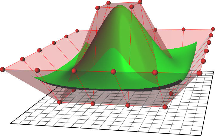
They can be efficiently handled by computer programs yet allow for easy human interaction. NURBS surfaces are functions of two parameters mapping to a surface in three-dimensional space. The shape of the surface is determined by control points. In a compact form, NURBS surfaces can represent simple geometrical shapes. For complex organic shapes, T-splines and subdivision surfaces are more suitable because they halve the number of control points in comparison with the NURBS surfaces.
In general, editing NURBS curves and surfaces is intuitive and predictable.[citation needed] Control points are always either connected directly to the curve or surface, or else act as if they were connected by a rubber band. Depending on the type of user interface, the editing of NURBS curves and surfaces can be via their control points (similar to Bézier curves) or via higher level tools such as spline modeling and hierarchical editing.
Before computers, designs were drawn by hand on paper with various drafting tools. Rulers were used for straight lines, compasses for circles, and protractors for angles. But many shapes, such as the freeform curve of a ship's bow, could not be drawn with these tools.
Although such curves could be drawn freehand at the drafting board, shipbuilders often needed a life-size version which could not be done by hand. Such large drawings were done with the help of flexible strips of wood, called splines. The splines were held in place at a number of predetermined points, by lead "ducks", named for the bill-shaped protrusion that the splines rested against. Between the ducks, the elasticity of the spline material caused the strip to take the shape that minimized the energy of bending, thus creating the smoothest possible shape that fit the constraints. The shape could be adjusted by moving the ducks.
In 1964, mathematicians started studying the spline shape, and derived the piecewise polynomial formula known as the spline curve or spline function. I. J. Schoenberg gave the spline function its name after its resemblance to the mechanical spline used by draftsmen.
As computers were introduced into the design process, the physical properties of such splines were investigated so that they could be modelled with mathematical precision and reproduced where needed. Pioneering work was done in France by Renault engineer Pierre Bézier, and Citroën's physicist and mathematician Paul de Casteljau. They worked nearly parallel to each other, but because Bézier published the results of his work, Bézier curves were named after him, while de Casteljau's name is only associated with related algorithms.
NURBS were initially used only in the proprietary CAD packages of car companies. Later they became part of standard computer graphics packages.
Hub AI
Non-uniform rational B-spline AI simulator
(@Non-uniform rational B-spline_simulator)
Non-uniform rational B-spline
Non-uniform rational basis spline (NURBS) is a mathematical model using basis splines (B-splines) that is commonly used in computer graphics for representing curves and surfaces. It offers great flexibility and precision for handling both analytic (defined by common mathematical formulae) and modeled shapes. It is a type of curve modeling, as opposed to polygonal modeling or digital sculpting. NURBS curves are commonly used in computer-aided design (CAD), manufacturing (CAM), and engineering (CAE). They are part of numerous industry-wide standards, such as IGES, STEP, ACIS, and PHIGS. Tools for creating and editing NURBS surfaces are found in various 3D graphics, rendering, and animation software packages.
They can be efficiently handled by computer programs yet allow for easy human interaction. NURBS surfaces are functions of two parameters mapping to a surface in three-dimensional space. The shape of the surface is determined by control points. In a compact form, NURBS surfaces can represent simple geometrical shapes. For complex organic shapes, T-splines and subdivision surfaces are more suitable because they halve the number of control points in comparison with the NURBS surfaces.
In general, editing NURBS curves and surfaces is intuitive and predictable.[citation needed] Control points are always either connected directly to the curve or surface, or else act as if they were connected by a rubber band. Depending on the type of user interface, the editing of NURBS curves and surfaces can be via their control points (similar to Bézier curves) or via higher level tools such as spline modeling and hierarchical editing.
Before computers, designs were drawn by hand on paper with various drafting tools. Rulers were used for straight lines, compasses for circles, and protractors for angles. But many shapes, such as the freeform curve of a ship's bow, could not be drawn with these tools.
Although such curves could be drawn freehand at the drafting board, shipbuilders often needed a life-size version which could not be done by hand. Such large drawings were done with the help of flexible strips of wood, called splines. The splines were held in place at a number of predetermined points, by lead "ducks", named for the bill-shaped protrusion that the splines rested against. Between the ducks, the elasticity of the spline material caused the strip to take the shape that minimized the energy of bending, thus creating the smoothest possible shape that fit the constraints. The shape could be adjusted by moving the ducks.
In 1964, mathematicians started studying the spline shape, and derived the piecewise polynomial formula known as the spline curve or spline function. I. J. Schoenberg gave the spline function its name after its resemblance to the mechanical spline used by draftsmen.
As computers were introduced into the design process, the physical properties of such splines were investigated so that they could be modelled with mathematical precision and reproduced where needed. Pioneering work was done in France by Renault engineer Pierre Bézier, and Citroën's physicist and mathematician Paul de Casteljau. They worked nearly parallel to each other, but because Bézier published the results of his work, Bézier curves were named after him, while de Casteljau's name is only associated with related algorithms.
NURBS were initially used only in the proprietary CAD packages of car companies. Later they became part of standard computer graphics packages.
Recent media