
Community hub
Recent from talks
Contribute something to knowledge base
Content stats: 0 posts, 0 articles, 1 media, 0 notes
Members stats: 0 subscribers, 0 contributors, 0 moderators, 0 supporters
Subscribers
Supporters
Contributors
Moderators
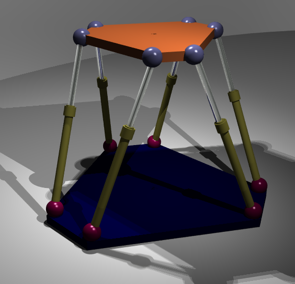
Parallel manipulator
A parallel manipulator is a mechanical system that uses several computer-controlled serial chains to support a single platform, or end-effector. Perhaps, the best known parallel manipulator is formed from six linear actuators that support a movable base for devices such as flight simulators. This device is called a Stewart platform or the Gough-Stewart platform in recognition of the engineers who first designed and used them.
Also known as parallel robots, or generalized Stewart platforms (in the Stewart platform, the actuators are paired together on both the basis and the platform), these systems are articulated robots that use similar mechanisms for the movement of either the robot on its base, or one or more manipulator arms. Their 'parallel' distinction, as opposed to a serial manipulator, is that the end effector (or 'hand') of this linkage (or 'arm') is directly connected to its base by a number of (usually three or six) separate and independent linkages working simultaneously. No geometrical parallelism is implied.
A parallel manipulator is designed so that each chain is usually short, simple and can thus be rigid against unwanted movement, compared to a serial manipulator. Errors in one chain's positioning are averaged in conjunction with the others, rather than being cumulative. Each actuator must still move within its own degree of freedom, as for a serial robot; however in the parallel robot the off-axis flexibility of a joint is also constrained by the effect of the other chains. It is this closed-loop stiffness that makes the overall parallel manipulator stiff relative to its components, unlike the serial chain that becomes progressively less rigid with more components.
This mutual stiffening also permits simple construction: Stewart platform hexapods chains use prismatic joint linear actuators between any-axis universal ball joints. The ball joints are passive: simply free to move, without actuators or brakes; their position is constrained solely by the other chains. Delta robots have base-mounted rotary actuators that move a light, stiff, parallelogram arm. The effector is mounted between the tips of three of these arms and again, it may be mounted with simple ball-joints. Static representation of a parallel robot is often akin to that of a pin-jointed truss: the links and their actuators feel only tension or compression, without any bending or torque, which again reduces the effects of any flexibility to off-axis forces.
A further advantage of the parallel manipulator is that the heavy actuators may often be centrally mounted on a single base platform, the movement of the arm taking place through struts and joints alone. This reduction in mass along the arm permits a lighter arm construction, thus lighter actuators and faster movements. This centralisation of mass also reduces the robot's overall moment of inertia, which may be an advantage for a mobile or walking robot.
All these features result in manipulators with a wide range of motion capability. As their speed of action is often constrained by their rigidity rather than sheer power, they can be fast-acting, in comparison to serial manipulators.
A manipulator can move an object with up to 6 degrees of freedom (DoF), determined by 3 translation 3T and 3 rotation 3R coordinates for full 3T3R mobility. However, when a manipulation task requires less than 6 DoF, the use of lower mobility manipulators, with fewer than 6 DoF, may bring advantages in terms of simpler architecture, easier control, faster motion and lower cost. For example, the 3 DoF Delta robot has lower 3T mobility and has proven to be very successful for rapid pick-and-place translational positioning applications. The workspace of lower mobility manipulators may be decomposed into `motion' and `constraint' subspaces. For example, 3 position coordinates constitute the motion subspace of the 3 DoF Delta robot and the 3 orientation coordinates are in the constraint subspace. The motion subspace of lower mobility manipulators may be further decomposed into independent (desired) and dependent subspaces: consisting of `concomitant' or `parasitic' motion which is undesired motion of the manipulator. The debilitating effects of parasitic motion should be mitigated or eliminated in the successful design of lower mobility manipulators. For example, the Delta robot does not have parasitic motion since its end effector does not rotate.
Most robot applications require rigidity. Serial robots may achieve this by using high-quality rotary joints that permit movement in one axis but are rigid against movement outside this. Any joint permitting movement must also have this movement under deliberate control by an actuator. A movement requiring several axes thus requires a number of such joints. Unwanted flexibility or sloppiness in one joint causes a similar sloppiness in the arm, which may be amplified by the distance between the joint and the end-effectuor: there is no opportunity to brace one joint's movement against another. Their inevitable hysteresis and off-axis flexibility accumulates along the arm's kinematic chain; a precision serial manipulator is a compromise between precision, complexity, mass (of the manipulator and of the manipulated objects) and cost. On the other hand, with parallel manipulators, a high rigidity may be obtained with a small mass of the manipulator (relatively to the charge being manipulated). This allows high precision and high speed of movements, and motivates the use of parallel manipulators in flight simulators (high speed with rather large masses) and electrostatic or magnetic lenses in particle accelerators (very high precision in positioning large masses).
Recent media
Recent media