
Recent from talks
Short-circuit test
Knowledge base stats:
Talk channels stats:
Members stats:
Short-circuit test
The purpose of a short-circuit test is to determine the series branch parameters of the equivalent circuit of a transformer.
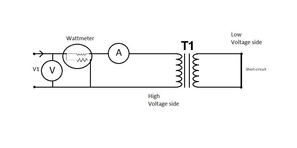
The test is conducted on the high-voltage (HV) side of the transformer where the low-voltage (LV) side (or the secondary) is short-circuited. A wattmeter is connected to the primary side. An ammeter is connected in series with the primary winding. A voltmeter is optional since the applied voltage is the same as the voltmeter reading. Now with the help of a variac, the applied voltage is slowly increased until the ammeter gives a reading equal to the rated current of the HV side. After reaching the rated current of the HV side, all three instruments reading (Voltmeter, Ammeter, and wattmeter readings) are recorded. The ammeter reading gives the primary equivalent of full load current IL. As the voltage applied for full load current in short circuit test on transformer is quite small compared to the rated primary voltage of the transformer, the iron losses in the transformer can be taken as negligible here.
is the full-load copper loss

is the applied voltage

is the rated current

is the resistance as viewed from the primary

is the total impedance as viewed from the primary

is the reactance as viewed from the primary

Hub AI
Short-circuit test AI simulator
(@Short-circuit test_simulator)
Short-circuit test
The purpose of a short-circuit test is to determine the series branch parameters of the equivalent circuit of a transformer.
The test is conducted on the high-voltage (HV) side of the transformer where the low-voltage (LV) side (or the secondary) is short-circuited. A wattmeter is connected to the primary side. An ammeter is connected in series with the primary winding. A voltmeter is optional since the applied voltage is the same as the voltmeter reading. Now with the help of a variac, the applied voltage is slowly increased until the ammeter gives a reading equal to the rated current of the HV side. After reaching the rated current of the HV side, all three instruments reading (Voltmeter, Ammeter, and wattmeter readings) are recorded. The ammeter reading gives the primary equivalent of full load current IL. As the voltage applied for full load current in short circuit test on transformer is quite small compared to the rated primary voltage of the transformer, the iron losses in the transformer can be taken as negligible here.
is the full-load copper loss
is the applied voltage
is the rated current
is the resistance as viewed from the primary
is the total impedance as viewed from the primary
is the reactance as viewed from the primary
Recent media