Recent from talks
Yamaha DX1
Knowledge base stats:
Talk channels stats:
Members stats:
Yamaha DX1
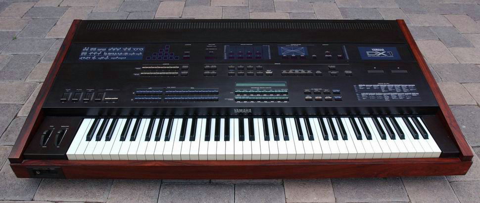
The Yamaha DX1 is the top-level member of Yamaha's prolific DX series of FM synthesizers. The DX1 has two sets of the synthesizer chipset used in the DX7, allowing either double the polyphony, split of two voices, or dual (layered) instrument voices. It also has double the voice memory of the DX7. It has an independent voice bank for each of two synthesizer channels ("sound engines"). Each of 64 performance combinations can be assigned a single voice number, or a combination of two voice numbers - one from channel A and one from channel B.
The DX1 was enclosed in a handmade Brazilian rosewood case and was played with a 73-key weighted wooden keyboard with polyphonic aftertouch. On the left side of the front panel, a printed algorithm chart provided an overview of the 32 selectable algorithms and their associated operator structuring.
The DX1 also used solid push-buttons rather than the membrane buttons found on the DX7, with them containing individual LEDs to indicate current status.
Compared to the DX5 and the DX7, the DX1 had more displays that enhanced accessibility and programmability.
The performance section had a backlit LCD (40 × 2 characters) which displayed selected programs in Single, Dual, or Split mode, as well as LFO settings and other voice-specific parameters.
The algorithm panel had a thirteen single-character 7-segment numeric displays for indicating the selected algorithm, by providing position and relationships of all active operators, as each on these displays were linked to neighbouring ones via individual stripe-style LEDs; the top display showed the of feedback and the bottom one showed the algorithm number.
The oscillator panel contained two LEDs for indicating frequency ratio (top) or fixed frequency (bottom) in Hz mode, a single LED to indicate positive or negative detune, one single-character numeric display (top) for detune amount, and one four-character numeric display (bottom) for value (ratio or exact frequency) of the selected frequency mode.
The envelope panel had two LEDs for indicating either centre pitch (left) or amplitude level mode (right), eight double-character numeric displays for showing each individual envelope parameter, and four 16-segment bar-style LEDs that graphically displayed either rates (in centre pitch mode) or levels (in amplitude mode).
Hub AI
Yamaha DX1 AI simulator
(@Yamaha DX1_simulator)
Yamaha DX1
The Yamaha DX1 is the top-level member of Yamaha's prolific DX series of FM synthesizers. The DX1 has two sets of the synthesizer chipset used in the DX7, allowing either double the polyphony, split of two voices, or dual (layered) instrument voices. It also has double the voice memory of the DX7. It has an independent voice bank for each of two synthesizer channels ("sound engines"). Each of 64 performance combinations can be assigned a single voice number, or a combination of two voice numbers - one from channel A and one from channel B.
The DX1 was enclosed in a handmade Brazilian rosewood case and was played with a 73-key weighted wooden keyboard with polyphonic aftertouch. On the left side of the front panel, a printed algorithm chart provided an overview of the 32 selectable algorithms and their associated operator structuring.
The DX1 also used solid push-buttons rather than the membrane buttons found on the DX7, with them containing individual LEDs to indicate current status.
Compared to the DX5 and the DX7, the DX1 had more displays that enhanced accessibility and programmability.
The performance section had a backlit LCD (40 × 2 characters) which displayed selected programs in Single, Dual, or Split mode, as well as LFO settings and other voice-specific parameters.
The algorithm panel had a thirteen single-character 7-segment numeric displays for indicating the selected algorithm, by providing position and relationships of all active operators, as each on these displays were linked to neighbouring ones via individual stripe-style LEDs; the top display showed the of feedback and the bottom one showed the algorithm number.
The oscillator panel contained two LEDs for indicating frequency ratio (top) or fixed frequency (bottom) in Hz mode, a single LED to indicate positive or negative detune, one single-character numeric display (top) for detune amount, and one four-character numeric display (bottom) for value (ratio or exact frequency) of the selected frequency mode.
The envelope panel had two LEDs for indicating either centre pitch (left) or amplitude level mode (right), eight double-character numeric displays for showing each individual envelope parameter, and four 16-segment bar-style LEDs that graphically displayed either rates (in centre pitch mode) or levels (in amplitude mode).
Recent media