
Community hub
Recent from talks
Contribute something
Nothing was collected or created yet.
AN/ARC-5
View on WikipediaThis article has multiple issues. Please help improve it or discuss these issues on the talk page. (Learn how and when to remove these messages)
|

The AN/ARC-5 Command Radio Set is a series of radio receivers, transmitters, and accessories carried aboard U.S. Navy aircraft during World War II and for some years afterward. It is described as "a complete multi-channel radio transmitting and receiving set providing communication and navigation facilities for aircraft. The LF-MF-HF components are designed to transmit and receive voice, tone-modulated, and continuous wave (cw) signals."[1]: 1 Its flexible design provided AM radiotelephone voice communication and Modulated continuous wave (MCW) and Continuous wave (CW) Morse code modes, all of which are typical capabilities in other Navy aircraft communication sets of the period. It was an improvement of the Navy's ARA/ATA command set. Similar units designated SCR-274-N were used in U.S. Army aircraft. The Army set is based on the ARA/ATA, not the later AN/ARC-5. The ARA/ATA and SCR-274-N series are informally referred to as "ARC-5", despite small differences that render all three series incompatible. Like the AN/ARC-5, the ARA/ATA and SCR-274-N had AM voice communication and two-way MCW and CW Morse code capability.[1]
In accordance with the Joint Electronics Type Designation System (JETDS), the "AN/ARC-5" designation represents the 5th design of an Army-Navy airborne electronic device for radio communications equipment. The JETDS system also now is used to name all Department of Defense electronic systems.
History
[edit]The AN/ARC-5 command set was used by the US Navy from the latter part of World War II into the post-war era. It was fitted in many different aircraft types for communication between aircraft, navigation, and communication back to base. Units were available that covered much of the MF, HF, and VHF spectrum. Despite the use of octal base vacuum tubes, they were compact, rugged and light weight. Many became surplus after the war and were often converted for amateur radio use. The term 'ARC-5', while correctly applied to the AN/ARC-5 series, has also come to be a generic, though incorrect, term for the ARA/ATA and SCR-274-N command set units, including those designed by the Aircraft Radio Corporation in the late 1930s.[2]
The antecedent of the AN/ARC-5 system was the U.S. Navy's ARA/ATA system, initially deployed in 1940. The designations ARA and ATA are a pre-World War II Navy equipment nomenclature. The major units of the ARA are five receivers covering 0.19 to 9.1 MHz (1,577.86 to 32.94 m), each unit with its own dynamotor power supply. The major units of the ATA are five transmitters covering 2.1 to 9.1 MHz (142.76 to 32.94 m), using a common transmitter dynamotor/screen modulator unit. Most units were made by the Aircraft Radio Corporation (USN manufacturer's code CBY). Many units were also made by Stromberg-Carlson (USN manufacturer's code CCT).
To equip US Army Air Corps planes, the US Army adopted in 1941 a reduced set of radios from the ARA/ATA range. Designated SCR-274-N, these Army radios were electrically almost identical to their ARA/ATA counterparts, except for receiver output and modulator sidetone audio transformer output impedance. Structurally and in appearance, they were virtually identical except for most later units being left unpainted aluminum in contrast to the black wrinkle finish of the Navy sets. The designation SCR-274-N is a pre-World War II Army equipment nomenclature. The Army never acquired the ARA 1.5 to 3 MHz (199.86 to 99.93 m) receiver, nor the ATA 2.1 to 3.0 MHz (142.76 to 99.93 m) transmitter. Initially, it did not acquire the 3.0 to 4.0 MHz (99.93 to 74.95 m) transmitter, nor the 0.52 to 1.5 MHz (576.52 to 199.86 m) receiver, but the need to communicate on the common civil airfield frequency of 3.105 MHz (96.55 m) plus the anticipated USAAF use of the AN/ARR-1 homing adapter (see below) compelled adding these units to the SCR-274-N. Early Army units were made by Aircraft Radio Corporation, but the vast majority was made by Western Electric, plus a few by Colonial Radio and others.
In late 1943, the U.S. Navy fielded an improved and more flexible set of its ARA/ATA radios under the new Joint Army-Navy (JAN) nomenclature of AN/ARC-5. Structurally and in appearance, the AN/ARC-5 series is almost identical to the former units but both receivers and transmitters are somewhat different electrically. A receiver and transmitter were added that provide four-channel crystal-controlled VHF-AM operation, along with a rarely encountered set of transmitters that provide coverage of 0.5 to 2.1 MHz (599.58 to 142.76 m).
The main units of both the Navy and the Army systems were usually installed in three-receiver racks and two-transmitter racks. Units not in service could be stored on board the aircraft, just as one would store tuning units of other types of radio equipment.
Specifications
[edit]The following is a table of ARA/ATA, SCR-274-N, and AN/ARC-5 major components that could comprise a typical three-receiver, two-transmitter installation, with other configurations also being possible. In addition, several miscellaneous components are listed. A blank in the component ID column indicates that no equivalent unit existed for that system. A.R.C. refers to Aircraft Radio Corporation.[3]: 3
| MHz | ARA-ATA | SCR-274-N | AN/ARC-5 | |
|---|---|---|---|---|
| Navigation Receiver (Beacon Band) | 0.19 - 0.55 | CBY-46129 | BC-453-(*) | R-23(†)/ARC-5 |
| Navigation Receiver (Broadcast Band) | 0.52 - 1.5 | CBY-46145 | BC-946-(*) | R-24/ARC-5 |
| Communication Receiver | 1.5 - 3.0 | CBY-46104[a] | R-25/ARC-5 | |
| Communication Receiver | 3.0 - 6.0 | CBY-46105[b] | BC-454-(*) | R-26/ARC-5 |
| Communication Receiver | 6.0 - 9.1 | CBY-46106[c] | BC-455-(*) | R-27/ARC-5 |
| Communication Receiver - Four Channel | 100 - 156 | R-28/ARC-5 | ||
| Communication Receiver - Continuously Tunable | 100 - 125 | R-112/ARC-5 | ||
| Communication Receiver - Continuously Tunable | 125 - 156 | R-113/ARC-5 | ||
| Special Use Transmitter | 0.5 - 0.8 | T-15/ARC-5 | ||
| Special Use Transmitter | 0.8 - 1.3 | T-16/ARC-5 | ||
| Special Use Transmitter | 1.3 - 2.1 | T-17/ARC-5 | ||
| Communication Transmitter | 2.1 - 3.0 | CBY-52232 | T-18/ARC-5 | |
| Communication Transmitter | 3.0 - 4.0 | CBY-52208 | BC-696-A | T-19/ARC-5 |
| Communication Transmitter | 4.0 - 5.3 | CBY-52209 | BC-457-A | T-20/ARC-5 |
| Communication Transmitter | 5.3 - 7.0 | CBY-52210 | BC-458-A | T-21/ARC-5 |
| Communication Transmitter | 7.0 - 9.1 | CBY-52211 | BC-459-A | T-22/ARC-5 |
| Communication Transmitter - Four Channel | 100 - 156 | T-23/ARC-5 | ||
| Communication Transmitter - Continuously Tunable | 100 - 125 | T-89/ARC-5 | ||
| Communication Transmitter - Continuously Tunable | 125 - 156 | T-90/ARC-5 | ||
| Communication Transmitter - Four Channel | 100 - 146 | T-126/ARC-5 | ||
| Transmitter Modulator | CBY-50083 | BC-456-(*) | MD-7/ARC-5 | |
| Transmitter Modulator Mount | CBY-50084 | FT-225-A | MT-76/ARC-5 | |
| MF/HF Antenna Relay | CBY-29125 | BC-442-(‡) | RE-2/ARC-5 | |
| MF/HF Antenna Relay Mount | CBY-29126 | FT-229-A | MT-77/ARC-5 | |
| Receiver Adapter, ILS (AN/ARN-9) Audio | MX-19/ARC-5 | |||
| Receiver Adapter, ZB (AN/ARR-1) Power | CBY-62036 | FT-310-A | MX-20/ARC-5 | |
| Receiver Adapter, Remote Control Blank | CBY-49107[d] | FT-230-A | MX-21/ARC-5 | |
| Receiver Local Tuning Knob | A.R.C. 6743 | MC-237 | A.R.C. 6743 | |
| Receiver Adapter, Local Control Panel | CBY-23154[e] | FT-260-A | C-24/ARC-5 | |
| Nav. Receiver ANT-LOOP Remote Control | C-25/ARC-5 | |||
| Single Tunable Receiver Control Box | CBY-23261 | BC-473-A | C-26/ARC-5 | |
| Single Lock-Tuned Receiver Control Box | C-27/ARC-5 | |||
| Single Tunable Receiver Control Mount | A.R.C. 7053 | FT-235-A | MT-4/ARR-2 | |
| Three-Receiver Remote Control Box | CBY-23251 | BC-450-A | C-38A/ARC-5 | |
| Three-Receiver Remote Control Mount | A.R.C. 7054 | FT-222-A | MT-98/ARC-5 | |
| Four-Transmitter Remote Control Box | CBY-23243 | BC-451-A | C-30(†)/ARC-5 | |
| Four-Transmitter Remote Control Mount | A.R.C. 7083 | FT-228-A | MT-80/ARC-5 | |
| Three-Receiver Rack | CBY-46149 | FT-220-A | MT-65/ARC-5 | |
| Three-Receiver Rack Mount | CBY-46150 | FT-221-A | MT-64/ARC-5 | |
| Two-Transmitter Rack | CBY-52212 | FT-226-A | MT-71/ARC-5 | |
| Two-Transmitter Rack Mount | CBY-52213 | FT-227-A | MT-70/ARC-5 | |
| Audio Jack Box | J-22/ARC-5 | |||
| Audio Jack Box Mount | MT-78/ARC-5 | |||
| Receiver Dynamotor | CBY-21531[f] | DM-32-A | DY-2(†)/ARR-2 | |
| Transmitter Dynamotor | CBY-21626 | DM-33-A | DY-8/ARC-5 | |
| Receiver Remote Tuning Shaft | A.R.C. 6151 | MC-215-A | A.R.C. 6151 | |
| Tuning Shaft Right Angle | A.R.C. 6357 | MC-211-A | MX-22/ARR-2 | |
| Homing Adapter | 234 - 258 | ZB-series | R-1/ARR-1 | R-1/ARR-1 |
| Homing Receiver | 234 - 258 | R-4(†)/ARR-2 |
Notes:
(*) A (basic model) or B (1st revision). (†) No letter (basic model) or A (revision). (‡) A (basic model) or AM (field modified to remove vacuum capacitor).
LF/MF/HF receivers all use an almost identical 6-tube superhet design: r.f. amplifier (12SK7), converter (12K8), two i.f. stages (two 12SK7's(4), or 12SK7/12SF7(5)), diode detector/BFO (12SR7), and one audio stage (12A6). Transmitters use four tubes: 1626 oscillator, two 1625 finals, and 1629 magic-eye tuning. The latter allows a check of the dial calibration by giving a visual indication, viewable by raising a small cover, when the oscillator's frequency matches that of an internal crystal.
(4)ARA and SCR-274-N. (5)AN/ARC-5.
Compatibility between systems
[edit]Audio frequency receiver output and modulator sidetone impedance for the ARA/ATA and the AN/ARC-5 is 300 to 600 ohms. In the SCR-274-N "-A" version, the receiver and modulator impedance is 4000 ohms, while "-B" and later version units have a 250 ohm tap on the AF transformers which can be connected.
ARA/ATA units and equivalent SCR-274-N units are interchangeable between systems, aside from audio impedance differences. However, AN/ARC-5 units generally are not interchangeable with the units of the earlier systems.
In contrast to ARA and SCR-274-N receivers, all AN/ARC-5 receivers have automatic volume control and a modified tube complement. The AN/ARC-5 navigation receivers have terminals and a switch to connect a DU-series direction finding loop to the receiver, and have a special audio line for an MX-19/ARC-5 adapter to allow the receiver to serve as an LF/MF localizer for the Navy's short-lived AN/ARN-9 Air-Track (related to ZA, ZAX) instrument landing system. These two capabilities were rarely if ever utilized. Otherwise, equivalent receivers of all three systems can interchange as a unit.
Few transmitter components of the AN/ARC-5 are interchangeable with ATA or SCR-274-N equivalent units. Mechanically, the transmitter rear power connector is slightly different, so inserting the wrong transmitter in a rack can damage either the rack or the transmitter power connector. Electrically, AN/ARC-5 transmitters use high-level final amplifier plate modulation, and the output tank circuit is shunt high voltage fed. The two earlier systems use less effective screen modulation, and the output circuit is series high voltage fed. The only electrical components of the AN/ARC-5 transmitter system that are interchangeable with the earlier systems are the dynamotor and the antenna relay.
Unlike earlier systems, none of the AN/ARC-5 control boxes have audio jacks for the microphone, headphone, or key. A separate jack box is used instead. AN/ARC-5 transmitter control boxes contain no Morse key.
Homing adaptors and VHF
[edit]The broadcast band receiver in all of these command sets is intended to host a homing adapter for the Navy ZB/YE homing system. The homing adapter demodulates a signal near 246 MHz (1.22 m) that is modulated with a broadcast band carrier. The output is sent to the broadcast band receiver tuned to the modulating frequency to further demodulate the carrier for voice messages or for a Morse code letter indicating to the pilot his bearing from the homing transmitter. All broadcast band receivers came with a power adapter to supply power to the homing adapter. The adapter under the Navy nomenclature system is the ZB-series. The identical unit under JAN nomenclature is the AN/ARR-1. This system was used by both the Navy extensively and the Army much less so. To put the system into operation on the aircraft, the beacon band receiver would be replaced in the rack by the broadcast band receiver. The antenna post is connected to the output of the homing adapter, and a power cable is connected from the homing adapter to the broadcast band receiver. The normal control that had been used for the beacon band receiver also serves this homing system without further reconfiguration.
Western Electric developed the AN/ARR-2, an all-in-one homing receiver that replaced the broadcast band receiver and external homing adapter and had other enhancements as well. The R-4A/ARR-2 uses the same dynamotor as the AN/ARC-5 sets, fits in the same racks, and can be controlled by special AN/ARC-5 control boxes. The AN/ARR-2 replaced the earlier R-24/ARC-5 and R-1/ARR-1 combo in AN/ARC-5 installations.
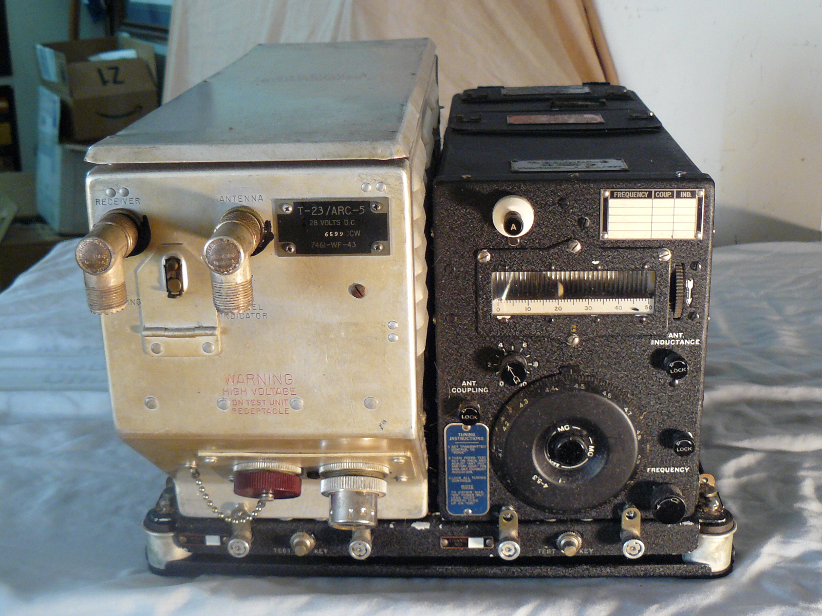
Western Electric developed a four-channel crystal-controlled VHF-AM receiver and transmitter for the U.S. Army's SCR-274-N system. The Army did not adopt these VHF components to any extent because of the move to a common British/American VHF capability in the form of the Bendix SCR-522 VHF-AM set. That remained Army policy until the arrival of the AN/ARC-3. The Navy adopted modified versions of the Western Electric units as the R-28/ARC-5 receiver and T-23/ARC-5 transmitter. The T-126/ARC-5 is a late variant of the T-23 which allowed the four channels to be grouped in a 100 to 146 MHz (3.00 to 2.05 m) tuning range, smaller than the T-23's.
Typical configuration
[edit]
A typical installation of ARA/ATA or SCR-274-N sets would consist of a 3 to 6 MHz (99.93 to 49.97 m), a 190 to 550 kHz (1,577.86 to 545.08 m), and a 6 to 9.1 MHz (49.97 to 32.94 m) receiver in a three-unit rack. Any two transmitters covering the desired frequency ranges would be in the transmitter rack. The two transmitters would be fixed-tuned before take-off, with the pilot able to select the desired transmitter and control the mode (Voice, MCW, CW) at the transmitter control box. The receivers were tuned at the pilot's control box by electrical cables and long mechanical tuning shafts, allowing remote control of power, mode, frequency, and volume.
AN/ARC-5 set composition and control differed markedly from the earlier systems. Three-unit receiver racks were still predominant, but the receiver line-up was quite different. One receiver would usually be a R-4A homing receiver, another the VHF R-28/ARC-5, and the last an MF/HF communication receiver. The transmitter rack would hold a VHF T-23/ARC-5 and an MF/HF transmitter corresponding to the MF/HF receiver. Frequency-stabilized versions of the AN/ARC-5 communications receivers usually have a yellow circle-S stamped on the front panel. Such receivers were not remotely tuned by the pilot, but were instead lock-tuned to the associated transmitter's frequency before take-off. AN/ARC-5 navigation receivers are not so stabilized, and if installed in the rack a control that allows remote tuning is required.
Because of these characteristics, AN/ARC-5 close equivalents to the control boxes of the ARA/ATA and SCR-274-N are rare or never existed. The most common AN/ARC-5 receiver remote control box is the C-38/ARC-5, which allows control only of audio volume of the VHF and MF/HF receivers. No power, mode, or frequency controls are present. The C-38 also has controls for the R-4A homing receiver. A common AN/ARC-5 transmitter control box C-30A/ARC-5 has controls for selecting the MF/HF transmitter or the VHF transmitter, and a switch to select the channel for both the VHF transmitter and receiver. Mode controls are normally set for voice and covered.
The typical AN/ARC-5 three-receiver, two-transmitter installation reflects system capabilities that are quite sophisticated compared to the earlier systems, allowing VHF homing, four channel VHF-AM communications, and one channel MF/HF-AM communications. All unnecessary controls have been eliminated to simplify operation of this more capable system.
Aircraft Radio Corporation, along with Stromberg-Carlson, made most AN/ARC-5 units except for the Western Electric VHF units.
Legacy
[edit]The AN/ARC-5 certainly represents the climax development of the pre-war MF/HF command set. But its VHF AN/ARC-5 set and the AN/ARR-2 homing adapter presaged a move toward higher frequencies. During World War II, the Navy began a slow movement toward VHF-AM for command functions in theaters where it made sense, beginning with the Western Electric WE-233A commercial airline set which was later re-designated the AN/ARC-4. By 1943 they began deploying their own AN/ARC-1 ten-channel VHF-AM set in increasing numbers, but hedged their bets with the AN/ARC-5 VHF sets in certain aircraft. This experimentation even caused them to contract for and officially nomenclature a continuously tunable AN/ARC-5 VHF capability from Aircraft Radio Corporation for evaluation purposes, shown in the above chart, but by that time (latter part of 1944) channelized equipment became the preferred technology to reduce aircrew "fiddling" with controls, so it was not pursued beyond the evaluation quantities. By late war, the discovery of "ducting" in the lower VHF band (that allowed Japanese tactical radio intercepts over long distances under certain conditions) drove development of the AN/ARC-12 (UHF version of the AN/ARC-1) and AN/ARC-27 sets in currently-used UHF-AM military aircraft band. However, it is important to understand that this gradual movement to VHF was not accomplished overnight, and there were still pockets of documented HF command set employment through war's end, especially in smaller aircraft.
In terms of longevity, the AN/ARR-2 continued into service well into the 1950s, and the beacon band R-23A/ARC-5 receiver was still to be found in some older US Navy aircraft as late as the 1970s.
Amateur radio use
[edit]
After World War II, surplus HF receivers and transmitters of the AN/ARC-5 family were extensively used in amateur radio stations. According to CQ magazine publisher Wayne Green, they first appeared for public purchase in March 1947, with thousands eventually becoming available, making them "by far the most popular surplus item to appear on the market." Green's magazine alone published some 47 articles on converting command sets to amateur use over the following 10 years, reprinting them in a compendium in 1957.[3]: pp. 3–5 Interest has continued into the 21st century.[4]
Other users
[edit]The T-16 and T-17 transmitters which operated in the standard broadcast band were very hard to find on the surplus market but were used by some as low power "pirate" AM stations with the addition of a modulation transformer in the B+ line and a suitable audio amplifier which was a 50 watt PA, guitar, or 'HI-FI home entertainment amplifier. The tuning system would allow the rig to be loaded into almost any kind of vertical or dipole antenna for neighborhood and beyond AM broadcasting. The on air fidelity of the unit was very good. One T-17 was used on 1580 by three different operators at three different locations in the Chicago suburbs as a pirate station in the 1960s with the local FCC office raiding each station at its location. The last raided operator repurposed the ARC5 as a driver for an ultrasonic nebulizer.
Gallery
[edit]-
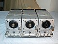 SCR-274-N:
Receivers
BC-454-B, BC-453-B,
BC-455-B
in Rack FT-220-A. -
 SCR-274-N:
Transmitters
BC-457-A, BC-459-A
in Rack FT-226-A. -
 SCR-274-N:
Receiver Control
BC-450-A,
Transmitter Control
BC-451-A,
Modulator
BC-456-B,
Antenna Relay
BC-442-A. -
 SCR-274-N and
AN/ARR-1:
Broadcast Band Receiver
BC-946-B,
Homing Adapter
R-1/ARR-1. -
 AN/ARC-5 and
AN/ARR-2:
Homing Receiver
R-4A/ARR-2,
HF Receiver
R-26/ARC-5,
VHF Receiver
R-28/ARC-5
in Rack
MT-65/ARC-5. -
 AN/ARC-5 and
AN/ARR-2:
Receiver Control
C-38/ARC-5,
Transmitter Control
C-30A/ARC-5,
Audio Jack Box
J-22/ARC-5,
Modulator
MD-7/ARC-5,
Antenna Relay
RE-2/ARC-5,
DC Power Filter
F-5/AR. -
 AN/ARC-5:
Single Tunable
Receiver Control
C-26/ARC-5,
Beacon Band Receiver
R-23A/ARC-5
with ILS Adapter
MX-19/ARC-5,
Broadcast Band Receiver
R-24/ARC-5 with
Local Control
C-24/ARC-5,
Local Control
Shorting Plug
MX-2/ARR-2. -
 Underside view of a BC-453, left half of stereo pair
 -
 Underside view of a BC-453, right half of stereo pair


See also
[edit]References
[edit]Footnotes
[edit]Notes
[edit]- ^ a b Handbook, Maintenance Instructions: AN/ARC-5 Aircraft Radio Equipment LF MF HF Components (PDF). 15 December 1954. Retrieved 23 October 2024.
- ^ Hanz, Mike. "Overview". AAF Radio. Retrieved 23 October 2024.
- ^ a b Wayne Green (1957). "Command Sets" (PDF). Radio Manual. Retrieved 12 September 2022.
…many articles have appeared in CQ during the last ten years covering modifications of the units. The demand for these articles has been so heavy that every issue of CQ that carried them was long ago sold out…
- ^ John Stanley (January 2016). "Using unmodified command set ARC-5 radios on the ham bands". QST. American Radio Relay League. pp. 38–41. ISSN 0033-4812.
Further reading
[edit]- NavAER 08-5Q-95 Handbook of OPERATING INSTRUCTIONS for MODEL AN/ARC-5 Aircraft Radio Equipment, 21 February 1944
- AN 16-30ARC5-2, Handbook of MAINTENANCE INSTRUCTIONS for MODEL AN/ARC-5 Aircraft Radio Equipment VOLUME 1 LF MF HF Components, 15 December 1954
- AN 08-10-195, Handbook of MAINTENANCE INSTRUCTIONS for MODEL AN/ARC-5 Aircraft Radio Equipment VOLUME 2 VHF Components, 10 April 1945
- NavAER 08-5Q-261, Handbook of OPERATING INSTRUCTIONS for MODEL AN/ARR-2 Aircraft Radio Equipment, 1 May 1944
- AN 16-30ARR2-2, Handbook of MAINTENANCE INSTRUCTIONS for MODEL AN/ARR-2 Aircraft Radio Equipment, 1 May 1954
- TO 12R2-3SCR274-2, Handbook, MAINTENANCE INSTRUCTIONS, RADIO SET SCR-274-N, 25 July 1956