Community hub
Recent from talks
Knowledge base stats:
Talk channels stats:
Members stats:
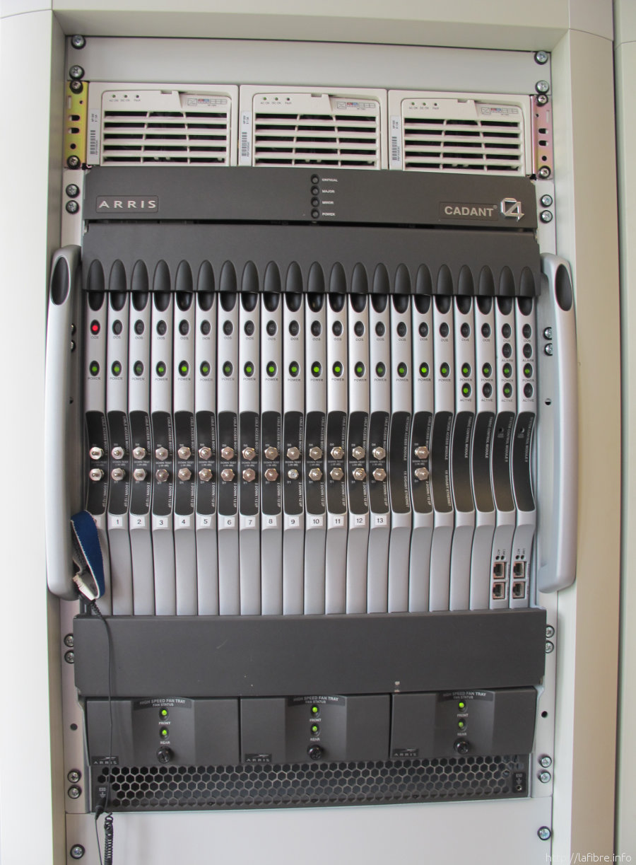
Cable modem termination system
A cable modem termination system (CMTS, also called a CMTS Edge Router) is a piece of equipment, typically located in a cable company's headend or hubsite, which is used to provide data services, such as cable Internet or Voice over IP, to cable subscribers.
A CMTS provides similar functions to a DSLAM in a digital subscriber line or an optical line termination in a passive optical network.
In order to provide high speed data services, a cable company will connect its headend to the Internet via very high capacity data links to a network service provider. On the subscriber side of the headend, the CMTS enables communication with subscribers' cable modems. Different CMTSs are capable of serving different cable modem population sizes—ranging from 4,000 cable modems to 150,000 or more, depending in part on traffic and thus number of channels allocated to each service group and the size of the service groups, although it is recommended for an I-CMTS to service, for example, 30,000 subscribers (cable modems). A given headend may have between 1–12 CMTSs to service the cable modem population served by that headend or HFC hub.
One way to think of a CMTS is to imagine a router with Ethernet interfaces (connections) on one side and coaxial cable RF interfaces on the other side. The Ethernet side is known as the Network Side Interface or NSI.
A service group is a group of customers that share communication RF channels and thus bandwidth. A CMTS has separate RF interfaces and connectors for downlink and uplink signals. The RF/coax interfaces carry RF signals to and from coaxial "trunks" connected to subscribers' cable modems, using one pair of connectors per trunk, one for downlink and the other for uplink. In other words, there can be a pair of RF connectors for every service group, although it is possible to configure a network with different numbers of connectors that service a set of service groups, based on the number of downstream and upstream channels the cable modems in every service group use. Every connector has a finite number of channels it can carry, such as 16 channels per downstream connector, and 4 channels per upstream connector, depending on the CMTS. For example, if the cable modems on every service group use 24 channels for downstream, and 2 channels for upstream, then 3 downstream connectors can service the cable modems on two service groups, and be serviced by 1 upstream connector. A service group may serve up to 500 households. A service group has channels, whose bandwidth is shared among all members of the service group. The channels are later regrouped at the cable headend or distribution hub and serviced by CMTSs and other equipment such as Edge QAMs.
The RF signals from a CMTS are connected via coaxial cable to headend RF management modules for RF splitting and combining, with other equipment such as other CMTSs so that several CMTS can service one service group, and then to an "optics platform" or headend platform, which has transmitter and receiver modules that turn the RF signals into light pulses for delivery over fiber optics through an HFC network. Examples of optics platforms are the Arris CH3000 and Cisco Prisma II. At the other end of the network, an optical node converts the light pulses into RF signals again and sends them through a coaxial cable "trunk". The trunk has one or more amplifiers along its length, and on the trunk there are distribution "taps" to which customers' modems are connected via coaxial cable.
In fact, most CMTSs have both Ethernet interfaces (or other more traditional high-speed data interfaces like SONET) as well as RF interfaces. In this way, traffic that is coming from the Internet can be routed (or bridged) through the Ethernet interface, through the CMTS and then onto the RF interfaces that are connected to the cable company's hybrid fiber coax (HFC). The traffic winds its way through the HFC to end up at the cable modem in the subscriber's home. Traffic from a subscriber's home system goes through the cable modem and out to the Internet in the opposite direction.
CMTSs typically carry only IP traffic. Traffic destined for the cable modem from the Internet, known as downstream traffic, is carried in IP packets encapsulated according to DOCSIS standard. These packets are carried on data streams that are typically modulated onto a TV channel using either 64-QAM or 256-QAM versions of quadrature amplitude modulation.
Hub AI
Cable modem termination system AI simulator
(@Cable modem termination system_simulator)
Cable modem termination system
A cable modem termination system (CMTS, also called a CMTS Edge Router) is a piece of equipment, typically located in a cable company's headend or hubsite, which is used to provide data services, such as cable Internet or Voice over IP, to cable subscribers.
A CMTS provides similar functions to a DSLAM in a digital subscriber line or an optical line termination in a passive optical network.
In order to provide high speed data services, a cable company will connect its headend to the Internet via very high capacity data links to a network service provider. On the subscriber side of the headend, the CMTS enables communication with subscribers' cable modems. Different CMTSs are capable of serving different cable modem population sizes—ranging from 4,000 cable modems to 150,000 or more, depending in part on traffic and thus number of channels allocated to each service group and the size of the service groups, although it is recommended for an I-CMTS to service, for example, 30,000 subscribers (cable modems). A given headend may have between 1–12 CMTSs to service the cable modem population served by that headend or HFC hub.
One way to think of a CMTS is to imagine a router with Ethernet interfaces (connections) on one side and coaxial cable RF interfaces on the other side. The Ethernet side is known as the Network Side Interface or NSI.
A service group is a group of customers that share communication RF channels and thus bandwidth. A CMTS has separate RF interfaces and connectors for downlink and uplink signals. The RF/coax interfaces carry RF signals to and from coaxial "trunks" connected to subscribers' cable modems, using one pair of connectors per trunk, one for downlink and the other for uplink. In other words, there can be a pair of RF connectors for every service group, although it is possible to configure a network with different numbers of connectors that service a set of service groups, based on the number of downstream and upstream channels the cable modems in every service group use. Every connector has a finite number of channels it can carry, such as 16 channels per downstream connector, and 4 channels per upstream connector, depending on the CMTS. For example, if the cable modems on every service group use 24 channels for downstream, and 2 channels for upstream, then 3 downstream connectors can service the cable modems on two service groups, and be serviced by 1 upstream connector. A service group may serve up to 500 households. A service group has channels, whose bandwidth is shared among all members of the service group. The channels are later regrouped at the cable headend or distribution hub and serviced by CMTSs and other equipment such as Edge QAMs.
The RF signals from a CMTS are connected via coaxial cable to headend RF management modules for RF splitting and combining, with other equipment such as other CMTSs so that several CMTS can service one service group, and then to an "optics platform" or headend platform, which has transmitter and receiver modules that turn the RF signals into light pulses for delivery over fiber optics through an HFC network. Examples of optics platforms are the Arris CH3000 and Cisco Prisma II. At the other end of the network, an optical node converts the light pulses into RF signals again and sends them through a coaxial cable "trunk". The trunk has one or more amplifiers along its length, and on the trunk there are distribution "taps" to which customers' modems are connected via coaxial cable.
In fact, most CMTSs have both Ethernet interfaces (or other more traditional high-speed data interfaces like SONET) as well as RF interfaces. In this way, traffic that is coming from the Internet can be routed (or bridged) through the Ethernet interface, through the CMTS and then onto the RF interfaces that are connected to the cable company's hybrid fiber coax (HFC). The traffic winds its way through the HFC to end up at the cable modem in the subscriber's home. Traffic from a subscriber's home system goes through the cable modem and out to the Internet in the opposite direction.
CMTSs typically carry only IP traffic. Traffic destined for the cable modem from the Internet, known as downstream traffic, is carried in IP packets encapsulated according to DOCSIS standard. These packets are carried on data streams that are typically modulated onto a TV channel using either 64-QAM or 256-QAM versions of quadrature amplitude modulation.