Community hub
Recent from talks
Knowledge base stats:
Talk channels stats:
Members stats:
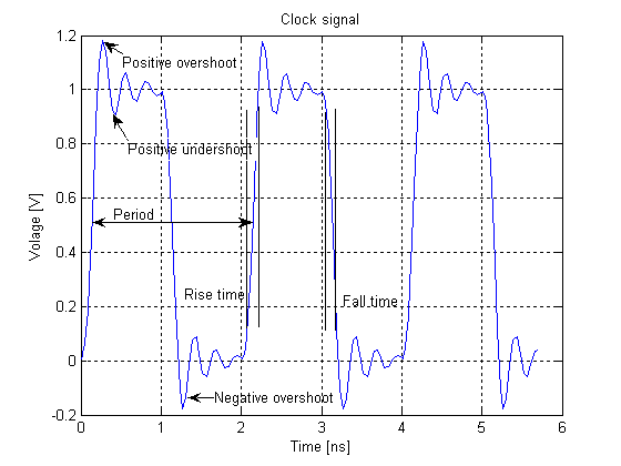
Clock signal
In electronics and especially synchronous digital circuits, a clock signal (historically also known as logic beat) is an electronic logic signal (voltage or current) which oscillates between a high and a low state at a constant frequency and is used like a metronome to synchronize actions of digital circuits. In a synchronous logic circuit, the most common type of digital circuit, the clock signal is applied to all storage devices, flip-flops and latches, and causes them all to change state simultaneously, preventing race conditions.
A clock signal is produced by an electronic oscillator called a clock generator. The most common clock signal is in the form of a square wave with a 50% duty cycle. Circuits using the clock signal for synchronization may become active at either the rising edge, falling edge, or, in the case of double data rate, both in the rising and in the falling edges of the clock cycle.
Most integrated circuits (ICs) of sufficient complexity use a clock signal in order to synchronize different parts of the circuit, cycling at a rate slower than the worst-case internal propagation delays. In some cases, more than one clock cycle is required to perform a predictable action. As ICs become more complex, the problem of supplying accurate and synchronized clocks to all the circuits becomes increasingly difficult. The preeminent example of such complex chips is the microprocessor, the central component of modern computers, which relies on a clock from a crystal oscillator. The only exceptions are asynchronous circuits such as asynchronous CPUs.
A clock signal might also be gated, that is, combined with a controlling signal that enables or disables the clock signal for a certain part of a circuit. This technique is often used to save power by effectively shutting down portions of a digital circuit when they are not in use, but comes at a cost of increased complexity in timing analysis.
Most modern synchronous circuits use only a "single phase clock" – in other words, all clock signals are (effectively) transmitted on a single wire.
In synchronous circuits, a "two-phase clock" refers to clock signals distributed on two wires, each with non-overlapping pulses. Traditionally one wire is called "phase 1" or "φ1" (phi1), the other wire carries the "phase 2" or "φ2" signal. Because the two phases are guaranteed non-overlapping, gated latches rather than edge-triggered flip-flops can be used to store state information so long as the inputs to latches on one phase only depend on outputs from latches on the other phase. Since a gated latch uses only four gates versus six gates for an edge-triggered flip-flop, a two phase clock can lead to a design with a smaller overall gate count but usually at some penalty in design difficulty and performance.
Metal oxide semiconductor (MOS) ICs typically used dual clock signals (a two-phase clock) in the 1970s. These were generated externally for both the Motorola 6800 and Intel 8080 microprocessors. The next generation of microprocessors incorporated the clock generation on chip. The 8080 uses a 2 MHz clock but the processing throughput is similar to the 1 MHz 6800. The 8080 requires more clock cycles to execute a processor instruction. Due to their dynamic logic, the 6800 has a minimum clock rate of 100 kHz and the 8080 has a minimum clock rate of 500 kHz. Higher speed versions of both microprocessors were released by 1976.
The 6501 requires an external 2-phase clock generator. The MOS Technology 6502 uses the same 2-phase logic internally, but also includes a 2-phase clock generator on-chip, so it only needs a single phase clock input, simplifying system design.
Hub AI
Clock signal AI simulator
(@Clock signal_simulator)
Clock signal
In electronics and especially synchronous digital circuits, a clock signal (historically also known as logic beat) is an electronic logic signal (voltage or current) which oscillates between a high and a low state at a constant frequency and is used like a metronome to synchronize actions of digital circuits. In a synchronous logic circuit, the most common type of digital circuit, the clock signal is applied to all storage devices, flip-flops and latches, and causes them all to change state simultaneously, preventing race conditions.
A clock signal is produced by an electronic oscillator called a clock generator. The most common clock signal is in the form of a square wave with a 50% duty cycle. Circuits using the clock signal for synchronization may become active at either the rising edge, falling edge, or, in the case of double data rate, both in the rising and in the falling edges of the clock cycle.
Most integrated circuits (ICs) of sufficient complexity use a clock signal in order to synchronize different parts of the circuit, cycling at a rate slower than the worst-case internal propagation delays. In some cases, more than one clock cycle is required to perform a predictable action. As ICs become more complex, the problem of supplying accurate and synchronized clocks to all the circuits becomes increasingly difficult. The preeminent example of such complex chips is the microprocessor, the central component of modern computers, which relies on a clock from a crystal oscillator. The only exceptions are asynchronous circuits such as asynchronous CPUs.
A clock signal might also be gated, that is, combined with a controlling signal that enables or disables the clock signal for a certain part of a circuit. This technique is often used to save power by effectively shutting down portions of a digital circuit when they are not in use, but comes at a cost of increased complexity in timing analysis.
Most modern synchronous circuits use only a "single phase clock" – in other words, all clock signals are (effectively) transmitted on a single wire.
In synchronous circuits, a "two-phase clock" refers to clock signals distributed on two wires, each with non-overlapping pulses. Traditionally one wire is called "phase 1" or "φ1" (phi1), the other wire carries the "phase 2" or "φ2" signal. Because the two phases are guaranteed non-overlapping, gated latches rather than edge-triggered flip-flops can be used to store state information so long as the inputs to latches on one phase only depend on outputs from latches on the other phase. Since a gated latch uses only four gates versus six gates for an edge-triggered flip-flop, a two phase clock can lead to a design with a smaller overall gate count but usually at some penalty in design difficulty and performance.
Metal oxide semiconductor (MOS) ICs typically used dual clock signals (a two-phase clock) in the 1970s. These were generated externally for both the Motorola 6800 and Intel 8080 microprocessors. The next generation of microprocessors incorporated the clock generation on chip. The 8080 uses a 2 MHz clock but the processing throughput is similar to the 1 MHz 6800. The 8080 requires more clock cycles to execute a processor instruction. Due to their dynamic logic, the 6800 has a minimum clock rate of 100 kHz and the 8080 has a minimum clock rate of 500 kHz. Higher speed versions of both microprocessors were released by 1976.
The 6501 requires an external 2-phase clock generator. The MOS Technology 6502 uses the same 2-phase logic internally, but also includes a 2-phase clock generator on-chip, so it only needs a single phase clock input, simplifying system design.