Recent from talks
Francis turbine
Knowledge base stats:
Talk channels stats:
Members stats:
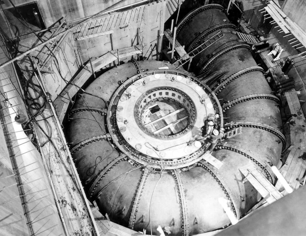
Francis turbine
The Francis turbine is a type of water turbine. It is an inward-flow reaction turbine that combines radial and axial flow concepts. Francis turbines are the most common water turbine in use today, and can achieve over 95% efficiency.
The process of arriving at the modern Francis runner design took from 1848 to approximately 1920. It became known as the Francis turbine around 1920, being named after British-American engineer James B. Francis who in 1848 created a new turbine design.
Francis turbines are primarily used for producing electricity. The power output of the electric generators generally ranges from just a few kilowatts up to 1000 MW, though mini-hydro installations may be lower. The best performance is seen when the head height is between 100–300 metres (330–980 ft). Penstock diameters are between 1 and 10 m (3.3 and 32.8 ft). The speeds of different turbine units range from 70 to 1000 rpm. A wicket gate around the outside of the turbine's rotating runner controls the rate of water flow through the turbine for different power production rates. Francis turbines are usually mounted with a vertical shaft, to isolate water from the generator. This also facilitates installation and maintenance.
Water wheels of different types have been used for more than 1,000 years to power mills of all types, but they were relatively inefficient. Nineteenth-century efficiency improvements of water turbines allowed them to replace nearly all water wheel applications and compete with steam engines wherever water power was available. After electric generators were developed in the late 1800s, turbines were a natural source of generator power where potential hydropower sources existed.
In 1826 the French engineer Benoit Fourneyron developed a high-efficiency (80%) outward-flow water turbine. Water was directed tangentially through the turbine runner, causing it to spin. Another French engineer, Jean-Victor Poncelet, designed an inward-flow turbine in about 1820 that used the same principles. S. B. Howd obtained a US patent in 1838 for a similar design.
In 1848 James B. Francis, while working as head engineer of the Locks and Canals company in the water wheel-powered textile factory city of Lowell, Massachusetts, improved on these designs to create more efficient turbines. He applied scientific principles and testing methods to produce a very efficient turbine design. More importantly, his mathematical and graphical calculation methods improved turbine design and engineering. His analytical methods allowed the design of high-efficiency turbines to precisely match a site's water flow and pressure (water head).
A Francis turbine consists of the following main parts:
Spiral casing: The spiral casing around the runner of the turbine is known as the volute casing or scroll case. Throughout its length, it has numerous openings at regular intervals to allow the working fluid to impinge on the blades of the runner. These openings convert the pressure energy of the fluid into kinetic energy just before the fluid impinges on the blades. This maintains a constant velocity despite the fact that numerous openings have been provided for the fluid to enter the blades, as the cross-sectional area of this casing decreases uniformly along the circumference.
Hub AI
Francis turbine AI simulator
(@Francis turbine_simulator)
Francis turbine
The Francis turbine is a type of water turbine. It is an inward-flow reaction turbine that combines radial and axial flow concepts. Francis turbines are the most common water turbine in use today, and can achieve over 95% efficiency.
The process of arriving at the modern Francis runner design took from 1848 to approximately 1920. It became known as the Francis turbine around 1920, being named after British-American engineer James B. Francis who in 1848 created a new turbine design.
Francis turbines are primarily used for producing electricity. The power output of the electric generators generally ranges from just a few kilowatts up to 1000 MW, though mini-hydro installations may be lower. The best performance is seen when the head height is between 100–300 metres (330–980 ft). Penstock diameters are between 1 and 10 m (3.3 and 32.8 ft). The speeds of different turbine units range from 70 to 1000 rpm. A wicket gate around the outside of the turbine's rotating runner controls the rate of water flow through the turbine for different power production rates. Francis turbines are usually mounted with a vertical shaft, to isolate water from the generator. This also facilitates installation and maintenance.
Water wheels of different types have been used for more than 1,000 years to power mills of all types, but they were relatively inefficient. Nineteenth-century efficiency improvements of water turbines allowed them to replace nearly all water wheel applications and compete with steam engines wherever water power was available. After electric generators were developed in the late 1800s, turbines were a natural source of generator power where potential hydropower sources existed.
In 1826 the French engineer Benoit Fourneyron developed a high-efficiency (80%) outward-flow water turbine. Water was directed tangentially through the turbine runner, causing it to spin. Another French engineer, Jean-Victor Poncelet, designed an inward-flow turbine in about 1820 that used the same principles. S. B. Howd obtained a US patent in 1838 for a similar design.
In 1848 James B. Francis, while working as head engineer of the Locks and Canals company in the water wheel-powered textile factory city of Lowell, Massachusetts, improved on these designs to create more efficient turbines. He applied scientific principles and testing methods to produce a very efficient turbine design. More importantly, his mathematical and graphical calculation methods improved turbine design and engineering. His analytical methods allowed the design of high-efficiency turbines to precisely match a site's water flow and pressure (water head).
A Francis turbine consists of the following main parts:
Spiral casing: The spiral casing around the runner of the turbine is known as the volute casing or scroll case. Throughout its length, it has numerous openings at regular intervals to allow the working fluid to impinge on the blades of the runner. These openings convert the pressure energy of the fluid into kinetic energy just before the fluid impinges on the blades. This maintains a constant velocity despite the fact that numerous openings have been provided for the fluid to enter the blades, as the cross-sectional area of this casing decreases uniformly along the circumference.
Recent media