



Community hub
Recent from talks
Knowledge base stats:
Talk channels stats:
Members stats:
Centrifugal governor
A centrifugal governor is a specific type of governor with a feedback system that controls the speed of an engine by regulating the flow of fuel or working fluid, so as to maintain a near-constant speed. It uses the principle of proportional control.
Centrifugal governors, also known as "centrifugal regulators" and "fly-ball governors", were invented by Christiaan Huygens and used to regulate the distance and pressure between millstones in windmills in the 17th century. In 1788, James Watt adapted one to control his steam engine where it regulates the admission of steam into the cylinder(s), a development that proved so important he is sometimes called the inventor. Centrifugal governors' widest use was on steam engines during the Steam Age in the 19th century. They are also found on stationary internal combustion engines and variously fueled turbines, and in some modern striking clocks.
A simple governor does not maintain an exact speed but a speed range, since under increasing load the governor opens the throttle as the speed (RPM) decreases.
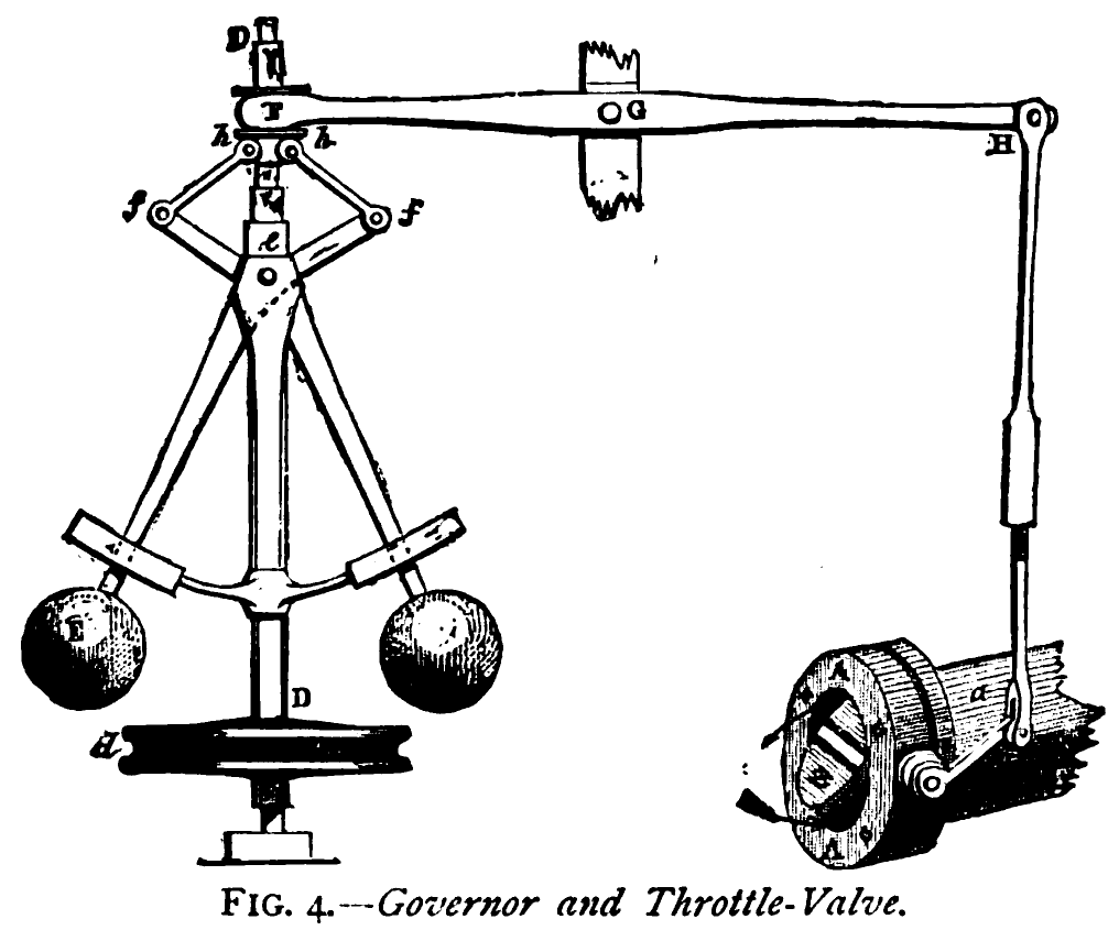
The devices shown are on steam engines. Power is supplied to the governor from the engine's output shaft by a belt or chain connected to the lower belt wheel. The governor is connected to a throttle valve that regulates the flow of working fluid (steam) supplying the prime mover. As the speed of the prime mover increases, the central spindle of the governor rotates at a faster rate, and the kinetic energy of the balls increases. This allows the two masses on lever arms to move outwards and upwards against gravity. If the motion goes far enough, this motion causes the lever arms to pull down on a thrust bearing, which moves a beam linkage, which reduces the aperture of a throttle valve. The rate of working-fluid entering the cylinder is thus reduced and the speed of the prime mover is controlled, preventing over-speeding.
Mechanical stops may be used to limit the range of throttle motion, as seen near the masses in the image at the top of this page.
A limitation of the two-arm, two-ball governor is its reliance on gravity to retract the balls when the governor slows down, and therefore a requirement that the governor stay upright.
Governors can be built that do not use gravitational force, by using a single straight arm with weights on both ends, a center pivot attached to a spinning axle, and a spring that tries to force the weights towards the center of the spinning axle. The two weights on opposite ends of the pivot arm counterbalance any gravitational effects, but both weights use centrifugal force to work against the spring and attempt to rotate the pivot arm towards a perpendicular axis relative to the spinning axle.
Spring-retracted non-gravitational governors are commonly used in single-phase alternating current (AC) induction motors to turn off the starting field coil when the motor's rotational speed is high enough. They are also commonly used in snowmobile and all-terrain vehicle (ATV) continuously variable transmissions (CVT), both to engage/disengage vehicle motion and to vary the transmission's pulley diameter ratio in relation to the engine revolutions per minute.
Hub AI
Centrifugal governor AI simulator
(@Centrifugal governor_simulator)
Centrifugal governor
A centrifugal governor is a specific type of governor with a feedback system that controls the speed of an engine by regulating the flow of fuel or working fluid, so as to maintain a near-constant speed. It uses the principle of proportional control.
Centrifugal governors, also known as "centrifugal regulators" and "fly-ball governors", were invented by Christiaan Huygens and used to regulate the distance and pressure between millstones in windmills in the 17th century. In 1788, James Watt adapted one to control his steam engine where it regulates the admission of steam into the cylinder(s), a development that proved so important he is sometimes called the inventor. Centrifugal governors' widest use was on steam engines during the Steam Age in the 19th century. They are also found on stationary internal combustion engines and variously fueled turbines, and in some modern striking clocks.
A simple governor does not maintain an exact speed but a speed range, since under increasing load the governor opens the throttle as the speed (RPM) decreases.
The devices shown are on steam engines. Power is supplied to the governor from the engine's output shaft by a belt or chain connected to the lower belt wheel. The governor is connected to a throttle valve that regulates the flow of working fluid (steam) supplying the prime mover. As the speed of the prime mover increases, the central spindle of the governor rotates at a faster rate, and the kinetic energy of the balls increases. This allows the two masses on lever arms to move outwards and upwards against gravity. If the motion goes far enough, this motion causes the lever arms to pull down on a thrust bearing, which moves a beam linkage, which reduces the aperture of a throttle valve. The rate of working-fluid entering the cylinder is thus reduced and the speed of the prime mover is controlled, preventing over-speeding.
Mechanical stops may be used to limit the range of throttle motion, as seen near the masses in the image at the top of this page.
A limitation of the two-arm, two-ball governor is its reliance on gravity to retract the balls when the governor slows down, and therefore a requirement that the governor stay upright.
Governors can be built that do not use gravitational force, by using a single straight arm with weights on both ends, a center pivot attached to a spinning axle, and a spring that tries to force the weights towards the center of the spinning axle. The two weights on opposite ends of the pivot arm counterbalance any gravitational effects, but both weights use centrifugal force to work against the spring and attempt to rotate the pivot arm towards a perpendicular axis relative to the spinning axle.
Spring-retracted non-gravitational governors are commonly used in single-phase alternating current (AC) induction motors to turn off the starting field coil when the motor's rotational speed is high enough. They are also commonly used in snowmobile and all-terrain vehicle (ATV) continuously variable transmissions (CVT), both to engage/disengage vehicle motion and to vary the transmission's pulley diameter ratio in relation to the engine revolutions per minute.