Community hub
Recent from talks
Knowledge base stats:
Talk channels stats:
Members stats:
Surface-mount technology
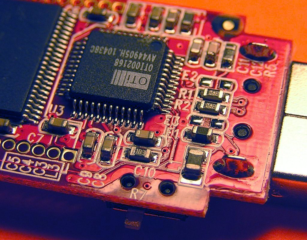
Surface-mount technology (SMT), originally called planar mounting, is a method in which the electrical components are mounted directly onto the surface of a printed circuit board (PCB). An electrical component mounted in this manner is referred to as a surface-mount device (SMD). In industry, this approach has largely replaced through-hole technology construction method of fitting components, in large part because SMT allows for increased manufacturing automation which reduces cost and improves quality. It also allows for more components to fit on a given area of substrate. Both technologies can be used on the same board, with the through-hole technology often used for components not suitable for surface mounting such as large transformers and heat-sinked power semiconductors.
An SMT component is usually smaller than its through-hole counterpart because it has either smaller leads or no leads at all. It may have short pins or leads of various styles, flat contacts, a matrix of solder balls (BGAs), or terminations on the body of the component.
Surface-mount technology was developed in the 1960s. By 1986, surface-mounted components accounted for 10% of the market at most but were rapidly gaining popularity. By the late 1990s, the great majority of high-tech electronic printed circuit assemblies were dominated by surface mount devices. Much of the pioneering work in this technology was done by IBM. The design approach first demonstrated by IBM in 1960 in a small-scale computer was later applied in the Launch Vehicle Digital Computer used in the Instrument Unit that guided all Saturn IB and Saturn V vehicles. Components were mechanically redesigned to have small metal tabs or end caps that could be directly soldered to the surface of the PCB. Components became much smaller, and component placement on both sides of a board became far more common with surface mounting than through-hole mounting, allowing much higher circuit densities and smaller circuit boards and, in turn, machines or subassemblies containing the boards.
Often, the surface tension of the solder is enough to hold the parts to the board; in rare cases, parts on the bottom or "second" side of the board may be secured with adhesive to keep components from dropping off inside reflow ovens. Adhesive is sometimes used to hold SMT components on the bottom side of a board if a wave soldering process is used to solder both SMT and through-hole components simultaneously. Alternatively, SMT and through-hole components can be soldered on the same side of a board without adhesive if the SMT parts are first reflow-soldered, then a selective solder mask is used to prevent the solder holding those parts in place from reflowing and the parts floating away during wave soldering. Surface mounting lends itself well to a high degree of automation, reducing labor cost and greatly increasing production rates.
Conversely, SMT does not lend itself well to manual or low-automation fabrication, which is more economical and faster for one-off prototyping and small-scale production; this is one reason why many through-hole components are still manufactured. Some SMDs can be soldered with a temperature-controlled manual soldering iron, but those that are very small or have too fine a lead pitch are often almost impossible to manually solder without expensive equipment.
Different terms describe the components, technique, and machines used in manufacturing. These terms are listed in the following table:
Where components are to be placed, the printed circuit board normally has flat, usually tin-lead, silver, or gold plated copper pads without holes, called solder pads. Solder paste, a sticky mixture of flux and tiny solder particles, is first applied to all the solder pads with a stainless steel or nickel stencil using a screen printing process. It can also be applied by a jet-printing mechanism, similar to an inkjet printer. After pasting, the boards proceed to the pick-and-place machines, where they are placed on a conveyor belt. The components to be placed on the boards are usually delivered to the production line in either paper/plastic tapes wound on reels or plastic tubes. Some large integrated circuits are delivered in static-free trays. Numerical control pick-and-place machines remove the parts from the tapes, tubes or trays and place them on the PCB.
The boards are then conveyed into the reflow soldering oven. They first enter a pre-heat zone, where the temperature of the board and all the components is gradually, uniformly raised to prevent thermal shock. The boards then enter a zone where the temperature is high enough to melt the solder particles in the solder paste, bonding the component leads to the pads on the circuit board. The surface tension of the molten solder helps keep the components in place. If the solder pad geometries are correctly designed, surface tension automatically aligns the components on their pads.
Hub AI
Surface-mount technology AI simulator
(@Surface-mount technology_simulator)
Surface-mount technology
Surface-mount technology (SMT), originally called planar mounting, is a method in which the electrical components are mounted directly onto the surface of a printed circuit board (PCB). An electrical component mounted in this manner is referred to as a surface-mount device (SMD). In industry, this approach has largely replaced through-hole technology construction method of fitting components, in large part because SMT allows for increased manufacturing automation which reduces cost and improves quality. It also allows for more components to fit on a given area of substrate. Both technologies can be used on the same board, with the through-hole technology often used for components not suitable for surface mounting such as large transformers and heat-sinked power semiconductors.
An SMT component is usually smaller than its through-hole counterpart because it has either smaller leads or no leads at all. It may have short pins or leads of various styles, flat contacts, a matrix of solder balls (BGAs), or terminations on the body of the component.
Surface-mount technology was developed in the 1960s. By 1986, surface-mounted components accounted for 10% of the market at most but were rapidly gaining popularity. By the late 1990s, the great majority of high-tech electronic printed circuit assemblies were dominated by surface mount devices. Much of the pioneering work in this technology was done by IBM. The design approach first demonstrated by IBM in 1960 in a small-scale computer was later applied in the Launch Vehicle Digital Computer used in the Instrument Unit that guided all Saturn IB and Saturn V vehicles. Components were mechanically redesigned to have small metal tabs or end caps that could be directly soldered to the surface of the PCB. Components became much smaller, and component placement on both sides of a board became far more common with surface mounting than through-hole mounting, allowing much higher circuit densities and smaller circuit boards and, in turn, machines or subassemblies containing the boards.
Often, the surface tension of the solder is enough to hold the parts to the board; in rare cases, parts on the bottom or "second" side of the board may be secured with adhesive to keep components from dropping off inside reflow ovens. Adhesive is sometimes used to hold SMT components on the bottom side of a board if a wave soldering process is used to solder both SMT and through-hole components simultaneously. Alternatively, SMT and through-hole components can be soldered on the same side of a board without adhesive if the SMT parts are first reflow-soldered, then a selective solder mask is used to prevent the solder holding those parts in place from reflowing and the parts floating away during wave soldering. Surface mounting lends itself well to a high degree of automation, reducing labor cost and greatly increasing production rates.
Conversely, SMT does not lend itself well to manual or low-automation fabrication, which is more economical and faster for one-off prototyping and small-scale production; this is one reason why many through-hole components are still manufactured. Some SMDs can be soldered with a temperature-controlled manual soldering iron, but those that are very small or have too fine a lead pitch are often almost impossible to manually solder without expensive equipment.
Different terms describe the components, technique, and machines used in manufacturing. These terms are listed in the following table:
Where components are to be placed, the printed circuit board normally has flat, usually tin-lead, silver, or gold plated copper pads without holes, called solder pads. Solder paste, a sticky mixture of flux and tiny solder particles, is first applied to all the solder pads with a stainless steel or nickel stencil using a screen printing process. It can also be applied by a jet-printing mechanism, similar to an inkjet printer. After pasting, the boards proceed to the pick-and-place machines, where they are placed on a conveyor belt. The components to be placed on the boards are usually delivered to the production line in either paper/plastic tapes wound on reels or plastic tubes. Some large integrated circuits are delivered in static-free trays. Numerical control pick-and-place machines remove the parts from the tapes, tubes or trays and place them on the PCB.
The boards are then conveyed into the reflow soldering oven. They first enter a pre-heat zone, where the temperature of the board and all the components is gradually, uniformly raised to prevent thermal shock. The boards then enter a zone where the temperature is high enough to melt the solder particles in the solder paste, bonding the component leads to the pads on the circuit board. The surface tension of the molten solder helps keep the components in place. If the solder pad geometries are correctly designed, surface tension automatically aligns the components on their pads.