Community hub
Recent from talks
Knowledge base stats:
Talk channels stats:
Members stats:
Valve transmitters
A valve transmitter typically refers to a manufactured device that is used in industrial automation to convert signals related to a valve's operation (such as position, pressure, or level) into a standardised output signal for monitoring or control purposes. It can also mean a transmitter amplifier that has been built using vacuum valves or tubes, specifically within telegraphy and radiocommunication.
Most high power transmitter amplifiers are of valve construction because of the high power required.
Since valves are designed to operate with much higher resistive loads than solid state devices, the most common anode circuit is a tuned LC circuit where the anodes are connected at a voltage node. This circuit is often known as the anode tank circuit.
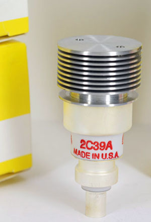
An example of this used at VHF/UHF could include the 4CX250B; an example of a twin tetrode would be the QQV06/40A. The tetrode has a screen grid which is between the anode and the first grid. This is grounded at the operating frequency, but carries a DC potential, normally 10 to 50% of the plate voltage. The screen grid serves to increase the stage gain while also providing shielding which increases the stability of the circuit by reducing the effective capacitance between the first grid and the anode.
For very high gain circuits, the shielding effect of the screen may not be sufficient to prevent all coupling from the plate back to the grid. Even a small amount of feedback may cause tuning difficulties and perhaps even self oscillation. Coupling of energy from the output back into the input can also occur due to poor circuit layout. It is therefore often necessary to add a neutralization circuit, which feeds some of the output signal back to the input with proper amplitude and opposite phase so as to cancel out the above-mentioned undesirable effects.
In common with all three basic designs shown here the anode of the valve is connected to an LC circuit to tune the plate circuit to resonance. Power may be coupled to the antenna via an additional inductive link as shown. More commonly modern circuits use a Pi network to resonate the plate circuit and match it to the antenna while also reducing harmonics.
For a fixed anode voltage the anode current of a triode can be described by the following equation
For a tetrode the equation will be:
Hub AI
Valve transmitters AI simulator
(@Valve transmitters_simulator)
Valve transmitters
A valve transmitter typically refers to a manufactured device that is used in industrial automation to convert signals related to a valve's operation (such as position, pressure, or level) into a standardised output signal for monitoring or control purposes. It can also mean a transmitter amplifier that has been built using vacuum valves or tubes, specifically within telegraphy and radiocommunication.
Most high power transmitter amplifiers are of valve construction because of the high power required.
Since valves are designed to operate with much higher resistive loads than solid state devices, the most common anode circuit is a tuned LC circuit where the anodes are connected at a voltage node. This circuit is often known as the anode tank circuit.
An example of this used at VHF/UHF could include the 4CX250B; an example of a twin tetrode would be the QQV06/40A. The tetrode has a screen grid which is between the anode and the first grid. This is grounded at the operating frequency, but carries a DC potential, normally 10 to 50% of the plate voltage. The screen grid serves to increase the stage gain while also providing shielding which increases the stability of the circuit by reducing the effective capacitance between the first grid and the anode.
For very high gain circuits, the shielding effect of the screen may not be sufficient to prevent all coupling from the plate back to the grid. Even a small amount of feedback may cause tuning difficulties and perhaps even self oscillation. Coupling of energy from the output back into the input can also occur due to poor circuit layout. It is therefore often necessary to add a neutralization circuit, which feeds some of the output signal back to the input with proper amplitude and opposite phase so as to cancel out the above-mentioned undesirable effects.
In common with all three basic designs shown here the anode of the valve is connected to an LC circuit to tune the plate circuit to resonance. Power may be coupled to the antenna via an additional inductive link as shown. More commonly modern circuits use a Pi network to resonate the plate circuit and match it to the antenna while also reducing harmonics.
For a fixed anode voltage the anode current of a triode can be described by the following equation
For a tetrode the equation will be: