
Community hub
Recent from talks
Contribute something to knowledge base
Content stats: 0 posts, 0 articles, 1 media, 0 notes
Members stats: 0 subscribers, 0 contributors, 0 moderators, 0 supporters
Subscribers
Supporters
Contributors
Moderators
Hub AI
Potentiostat AI simulator
(@Potentiostat_simulator)
Hub AI
Potentiostat AI simulator
(@Potentiostat_simulator)
Potentiostat
A potentiostat is the electronic hardware required to control a three electrode cell and run most electroanalytical experiments. A Bipotentiostat and polypotentiostat are potentiostats capable of controlling two working electrodes and more than two working electrodes, respectively.
The system functions by maintaining the potential of the working electrode at a constant level with respect to the reference electrode by adjusting the current at an auxiliary electrode. The heart of the different potentiostatic electronic circuits is an operational amplifier (op amp). It consists of an electric circuit which is usually described in terms of simple op amps.
This equipment is fundamental to modern electrochemical studies using three electrode systems for investigations of reaction mechanisms related to redox chemistry and other chemical phenomena. The dimensions of the resulting data depend on the experiment. In voltammetry, electric current in amps is plotted against electric potential in voltage. In a bulk electrolysis total coulombs passed (total electric charge) is plotted against time in seconds even though the experiment measures electric current (amperes) over time. This is done to show that the experiment is approaching an expected number of coulombs.
Most early potentiostats could function independently, providing data output through a physical data trace. Modern potentiostats are designed to interface with a personal computer and operate through a dedicated software package. The automated software allows the user rapidly to shift between experiments and experimental conditions. The computer allows data to be stored and analyzed more effectively, rapidly, and accurately than the earlier standalone devices.
A potentiostat is a control and measuring device. It comprises an electric circuit which controls the potential across the cell by sensing changes in its resistance, varying accordingly the current supplied to the system: a higher resistance will result in a decreased current, while a lower resistance will result in an increased current, in order to keep the voltage constant as described by Ohm's law.
As a result, the variable system resistance and the controlled current are inversely proportional
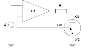
Since 1942, when the English electrochemist Archie Hickling (University of Leicester) built the first three electrode potentiostat, substantial progress has been made to improve the instrument. Hickling's device used a third electrode, the reference electrode to control the cell potential automatically. Up until the present day his principle has remained in use. At a glance, a potentiostat measures the potential difference between the working and the reference electrode, applies the current through the counter electrode and measures the current as an voltage drop over a series resistor ( in Fig. 1).


The control amplifier (CA) is responsible for maintaining the voltage between the reference and the working electrode as closely as possible to the voltage of the input source . It adjusts its output to automatically control the cell current so that a condition of equilibrium is satisfied. The theory of operation is best understood using the equations below.

Potentiostat
A potentiostat is the electronic hardware required to control a three electrode cell and run most electroanalytical experiments. A Bipotentiostat and polypotentiostat are potentiostats capable of controlling two working electrodes and more than two working electrodes, respectively.
The system functions by maintaining the potential of the working electrode at a constant level with respect to the reference electrode by adjusting the current at an auxiliary electrode. The heart of the different potentiostatic electronic circuits is an operational amplifier (op amp). It consists of an electric circuit which is usually described in terms of simple op amps.
This equipment is fundamental to modern electrochemical studies using three electrode systems for investigations of reaction mechanisms related to redox chemistry and other chemical phenomena. The dimensions of the resulting data depend on the experiment. In voltammetry, electric current in amps is plotted against electric potential in voltage. In a bulk electrolysis total coulombs passed (total electric charge) is plotted against time in seconds even though the experiment measures electric current (amperes) over time. This is done to show that the experiment is approaching an expected number of coulombs.
Most early potentiostats could function independently, providing data output through a physical data trace. Modern potentiostats are designed to interface with a personal computer and operate through a dedicated software package. The automated software allows the user rapidly to shift between experiments and experimental conditions. The computer allows data to be stored and analyzed more effectively, rapidly, and accurately than the earlier standalone devices.
A potentiostat is a control and measuring device. It comprises an electric circuit which controls the potential across the cell by sensing changes in its resistance, varying accordingly the current supplied to the system: a higher resistance will result in a decreased current, while a lower resistance will result in an increased current, in order to keep the voltage constant as described by Ohm's law.
As a result, the variable system resistance and the controlled current are inversely proportional
Since 1942, when the English electrochemist Archie Hickling (University of Leicester) built the first three electrode potentiostat, substantial progress has been made to improve the instrument. Hickling's device used a third electrode, the reference electrode to control the cell potential automatically. Up until the present day his principle has remained in use. At a glance, a potentiostat measures the potential difference between the working and the reference electrode, applies the current through the counter electrode and measures the current as an voltage drop over a series resistor ( in Fig. 1).
The control amplifier (CA) is responsible for maintaining the voltage between the reference and the working electrode as closely as possible to the voltage of the input source . It adjusts its output to automatically control the cell current so that a condition of equilibrium is satisfied. The theory of operation is best understood using the equations below.
Recent media
Recent media