
Community hub
Recent from talks
Contribute something to knowledge base
Content stats: 0 posts, 0 articles, 1 media, 0 notes
Members stats: 0 subscribers, 0 contributors, 0 moderators, 0 supporters
Subscribers
Supporters
Contributors
Moderators
Hub AI
Spiral antenna AI simulator
(@Spiral antenna_simulator)
Hub AI
Spiral antenna AI simulator
(@Spiral antenna_simulator)
Spiral antenna
A spiral antenna is a type of radio frequency antenna shaped as a spiral, first described in 1956. Archimedean spiral antennas are the most popular, while logarithmic spiral antennas are independent of frequency: the driving point impedance, radiation pattern and polarization of such antennas remain unchanged over a large bandwidth. Spiral antennas are inherently circularly polarized with low gain; antenna arrays can be used to increase the gain. Spiral antennas are reduced in size with its windings making it an extremely small structure. Lossy cavities are usually placed at the back to eliminate back lobes, because a unidirectional pattern is usually preferred in such antennas. Spiral antennas are classified into different configurations: Archimedean spiral, logarithmic spiral, square spiral, etc.
In general, antennas may operate in three different modes: traveling wave, fast wave, and leaky wave. Spiral antennas use all three.
The traveling wave, formed on spiral arms, allows for broadband performance. Fast wave is due to mutual coupling phenomenon occurring between arms of spiral. Leaky wave “leaks” the energy during propagation through the spiral arms to produce radiation.
Ring theory (band theory) explains the working principle of spiral antenna. The theory states that spiral antenna radiate from an active region where the circumference of the spiral equals the wavelength.
Different design parameters are to be considered while designing a square spiral antenna. The parameters include spacing between the turns , width of arm , inner radius and outer radius . The inner radius is measured from center of the spiral to center of the first turn while the outer radius is measured from center of the spiral to center of the outermost turn. Other than these design parameters, spiral antennas have lowest ( and highest operating frequencies. Here corresponds to speed of light in the metal of the antenna, mainly determined by the electrical permittivity of the substrate the spiral lies on, and its over-coating (if any).


In a polar coordinate system, the spiral grows along the -axis and -axis simultaneously. Often-used Archemedian spirals satisfy a particularly simple equation where corresponds to growth factor and corresponds to multiplication factor. The consequence is equal spacing between successive turns, which limits the width of the spiral arms, which is usually kept constant. Other choices of spiral shape can also be used, such as logarithmic spirals that satisfy ; the resulting spiral arms are more widely spaced in the outer turns, which can better accommodate arms that widen significantly.


Different designs of spiral antenna can be obtained by varying number of turns for each arm, the number of arms, the type of spiral, the spacing between its turns, the variation of the width of its arm(s), and the material(s) that surround it, such as the substrate it lies on.
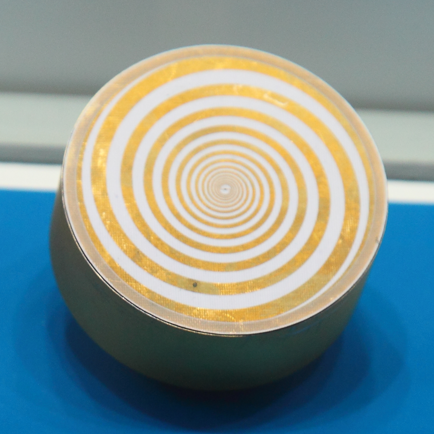
The antenna usually has two conductive spiral arms, extending from the center outwards. The direction of rotation of the spiral defines the direction of antenna polarization. Additional spirals may be included as well, to form a multi-spiral structure. The antenna may be a flat disc, with conductors resembling a pair of loosely nested clock springs, or the spirals may extend in a three-dimensional shape like a screw thread.
Spiral antenna
A spiral antenna is a type of radio frequency antenna shaped as a spiral, first described in 1956. Archimedean spiral antennas are the most popular, while logarithmic spiral antennas are independent of frequency: the driving point impedance, radiation pattern and polarization of such antennas remain unchanged over a large bandwidth. Spiral antennas are inherently circularly polarized with low gain; antenna arrays can be used to increase the gain. Spiral antennas are reduced in size with its windings making it an extremely small structure. Lossy cavities are usually placed at the back to eliminate back lobes, because a unidirectional pattern is usually preferred in such antennas. Spiral antennas are classified into different configurations: Archimedean spiral, logarithmic spiral, square spiral, etc.
In general, antennas may operate in three different modes: traveling wave, fast wave, and leaky wave. Spiral antennas use all three.
The traveling wave, formed on spiral arms, allows for broadband performance. Fast wave is due to mutual coupling phenomenon occurring between arms of spiral. Leaky wave “leaks” the energy during propagation through the spiral arms to produce radiation.
Ring theory (band theory) explains the working principle of spiral antenna. The theory states that spiral antenna radiate from an active region where the circumference of the spiral equals the wavelength.
Different design parameters are to be considered while designing a square spiral antenna. The parameters include spacing between the turns , width of arm , inner radius and outer radius . The inner radius is measured from center of the spiral to center of the first turn while the outer radius is measured from center of the spiral to center of the outermost turn. Other than these design parameters, spiral antennas have lowest ( and highest operating frequencies. Here corresponds to speed of light in the metal of the antenna, mainly determined by the electrical permittivity of the substrate the spiral lies on, and its over-coating (if any).
In a polar coordinate system, the spiral grows along the -axis and -axis simultaneously. Often-used Archemedian spirals satisfy a particularly simple equation where corresponds to growth factor and corresponds to multiplication factor. The consequence is equal spacing between successive turns, which limits the width of the spiral arms, which is usually kept constant. Other choices of spiral shape can also be used, such as logarithmic spirals that satisfy ; the resulting spiral arms are more widely spaced in the outer turns, which can better accommodate arms that widen significantly.
Different designs of spiral antenna can be obtained by varying number of turns for each arm, the number of arms, the type of spiral, the spacing between its turns, the variation of the width of its arm(s), and the material(s) that surround it, such as the substrate it lies on.
The antenna usually has two conductive spiral arms, extending from the center outwards. The direction of rotation of the spiral defines the direction of antenna polarization. Additional spirals may be included as well, to form a multi-spiral structure. The antenna may be a flat disc, with conductors resembling a pair of loosely nested clock springs, or the spirals may extend in a three-dimensional shape like a screw thread.
Recent media
Recent media