Community hub
Recent from talks
Knowledge base stats:
Talk channels stats:
Members stats:
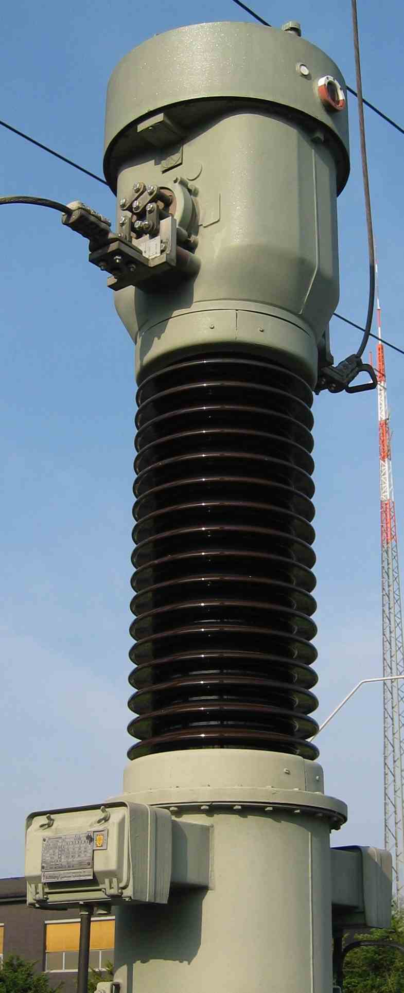
Current transformer
A current transformer (CT) is a type of transformer that reduces or multiplies alternating current (AC), producing a current in its secondary which is proportional to the current in its primary.
Current transformers, along with voltage or potential transformers, are instrument transformers, which scale the large values of voltage or current to small, standardized values that are easy to handle for measuring instruments and protective relays. Instrument transformers isolate measurement or protection circuits from the high voltage of the primary system. A current transformer presents a negligible load to the primary circuit.
Current transformers are the current-sensing units of the power system and are used at generating stations, electrical substations, and in industrial and commercial electric power distribution.
A current transformer has a primary winding, a core, and a secondary winding, although some transformers use an air core. While the physical principles are the same, the details of a "current" transformer compared with a "voltage" transformer will differ because of different requirements of the application. A current transformer is designed to maintain an accurate ratio between the currents in its primary and secondary circuits over a defined range.
The alternating current in the primary produces an alternating magnetic field in the core, which then induces an alternating current in the secondary. The primary circuit is largely unaffected by the insertion of the CT. Accurate current transformers need close coupling between the primary and secondary to ensure that the secondary current is proportional to the primary current over a wide current range. The current in the secondary is the current in the primary (assuming a single turn primary) divided by the number of turns of the secondary. In the illustration on the right, 'I' is the current in the primary, 'B' is the magnetic field, 'N' is the number of turns on the secondary, and 'A' is an AC ammeter.
Current transformers typically consist of a silicon steel ring core wound with many turns of copper wire, as shown in the illustration to the right. The conductor carrying the primary current is passed through the ring. The CT's primary, therefore, consists of a single 'turn'. The primary 'winding' may be a permanent part of the current transformer, i.e., a heavy copper bar to carry current through the core. Window-type current transformers are also common, which can have circuit cables run through the middle of an opening in the core to provide a single-turn primary winding. To assist accuracy, the primary conductor should be centered in the aperture.
CTs are specified by their current ratio from primary to secondary. The rated secondary current is normally standardized at 1 or 5 amperes. For example, a 4000:5 CT secondary winding will supply an output current of 5 amperes when the primary winding current is 4000 amperes. This ratio can also be used to find the impedance or voltage on one side of the transformer, given the appropriate value at the other side. For the 4000:5 CT, the secondary impedance can be found as ZS = NZP = 800ZP, and the secondary voltage can be found as VS = NVP = 800VP. In some cases, the secondary impedance is referred to the primary side, and is found as ZS′ = N2ZP. Referring the impedance is done simply by multiplying initial secondary impedance value by the current ratio. The secondary winding of a CT can have taps to provide a range of ratios, five taps being common.
Current transformer shapes and sizes vary depending on the end-user or switch gear manufacturer. Low-voltage single ratio metering current transformers are either a ring type or plastic molded case.
Hub AI
Current transformer AI simulator
(@Current transformer_simulator)
Current transformer
A current transformer (CT) is a type of transformer that reduces or multiplies alternating current (AC), producing a current in its secondary which is proportional to the current in its primary.
Current transformers, along with voltage or potential transformers, are instrument transformers, which scale the large values of voltage or current to small, standardized values that are easy to handle for measuring instruments and protective relays. Instrument transformers isolate measurement or protection circuits from the high voltage of the primary system. A current transformer presents a negligible load to the primary circuit.
Current transformers are the current-sensing units of the power system and are used at generating stations, electrical substations, and in industrial and commercial electric power distribution.
A current transformer has a primary winding, a core, and a secondary winding, although some transformers use an air core. While the physical principles are the same, the details of a "current" transformer compared with a "voltage" transformer will differ because of different requirements of the application. A current transformer is designed to maintain an accurate ratio between the currents in its primary and secondary circuits over a defined range.
The alternating current in the primary produces an alternating magnetic field in the core, which then induces an alternating current in the secondary. The primary circuit is largely unaffected by the insertion of the CT. Accurate current transformers need close coupling between the primary and secondary to ensure that the secondary current is proportional to the primary current over a wide current range. The current in the secondary is the current in the primary (assuming a single turn primary) divided by the number of turns of the secondary. In the illustration on the right, 'I' is the current in the primary, 'B' is the magnetic field, 'N' is the number of turns on the secondary, and 'A' is an AC ammeter.
Current transformers typically consist of a silicon steel ring core wound with many turns of copper wire, as shown in the illustration to the right. The conductor carrying the primary current is passed through the ring. The CT's primary, therefore, consists of a single 'turn'. The primary 'winding' may be a permanent part of the current transformer, i.e., a heavy copper bar to carry current through the core. Window-type current transformers are also common, which can have circuit cables run through the middle of an opening in the core to provide a single-turn primary winding. To assist accuracy, the primary conductor should be centered in the aperture.
CTs are specified by their current ratio from primary to secondary. The rated secondary current is normally standardized at 1 or 5 amperes. For example, a 4000:5 CT secondary winding will supply an output current of 5 amperes when the primary winding current is 4000 amperes. This ratio can also be used to find the impedance or voltage on one side of the transformer, given the appropriate value at the other side. For the 4000:5 CT, the secondary impedance can be found as ZS = NZP = 800ZP, and the secondary voltage can be found as VS = NVP = 800VP. In some cases, the secondary impedance is referred to the primary side, and is found as ZS′ = N2ZP. Referring the impedance is done simply by multiplying initial secondary impedance value by the current ratio. The secondary winding of a CT can have taps to provide a range of ratios, five taps being common.
Current transformer shapes and sizes vary depending on the end-user or switch gear manufacturer. Low-voltage single ratio metering current transformers are either a ring type or plastic molded case.