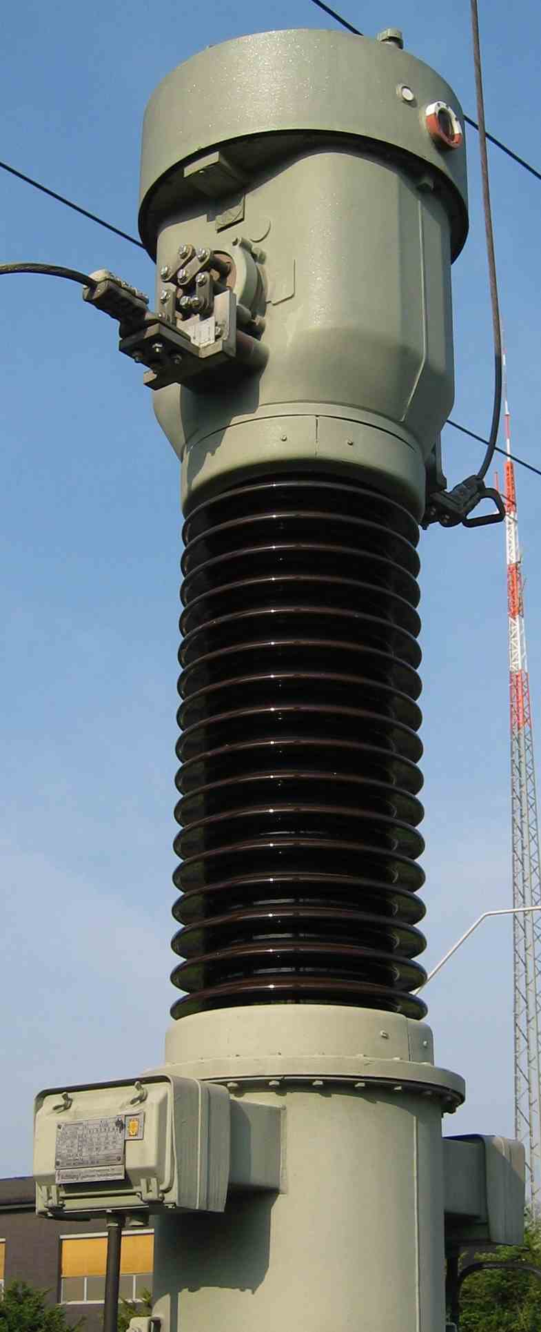
Current transformer
Current transformer
Main page
2085668

Current transformer

logo
Community Hub0 subscribers
Read side by side
from Wikipedia
A CT for operation on a 110 kV grid

A current transformer (CT) is a type of transformer that reduces or multiplies alternating current (AC), producing a current in its secondary which is proportional to the current in its primary.

Current transformers, along with voltage or potential transformers, are instrument transformers, which scale the large values of voltage or current to small, standardized values that are easy to handle for measuring instruments and protective relays. Instrument transformers isolate measurement or protection circuits from the high voltage of the primary system. A current transformer presents a negligible load to the primary circuit.[1]

Current transformers are the current-sensing units of the power system and are used at generating stations, electrical substations, and in industrial and commercial electric power distribution.

Function

[edit]
Basic operation of current transformer
SF6 110 kV current transformer TGFM series, Russia
Current transformers used in metering equipment for three-phase 400-ampere electricity supply

A current transformer has a primary winding, a core, and a secondary winding, although some transformers use an air core. While the physical principles are the same, the details of a "current" transformer compared with a "voltage" transformer differ because of different requirements of the application. A current transformer is designed to maintain an accurate ratio between the currents in its primary and secondary circuits over a defined range.

The alternating current in the primary produces an alternating magnetic field in the core, which then induces an alternating current in the secondary. The primary circuit is largely unaffected by the insertion of the CT. Accurate current transformers need close coupling between the primary and secondary to ensure that the secondary current is proportional to the primary current over a wide current range. The current in the secondary is the current in the primary (assuming a single turn primary) divided by the number of turns of the secondary. In the illustration on the right, 'I' is the current in the primary, 'B' is the magnetic field, 'N' is the number of turns on the secondary, and 'A' is an AC ammeter.

Current transformers typically consist of a silicon steel ring core wound with many turns of copper wire, as shown in the illustration to the right. The conductor carrying the primary current is passed through the ring. The CT's primary, therefore, consists of a single 'turn'. The primary 'winding' may be a permanent part of the current transformer, i.e., a heavy copper bar to carry current through the core. Window-type (toroidal) current transformers are also common, which can have circuit cables run through the center of the core to provide a single-turn primary winding. To assist accuracy, the primary conductor should be centered in the aperture.

CTs are specified by their current ratio from primary to secondary. The rated secondary current is normally standardized at 1 or 5 amperes. For example, a 4000:5 CT secondary winding will supply an output current of 5 amperes when the primary winding current is 4000 amperes. This ratio can also be used to find the impedance or voltage on one side of the transformer, given the appropriate value at the other side. For the 4000:5 CT, the secondary impedance can be found as ZS = NZP = 800ZP, and the secondary voltage can be found as VS = NVP = 800VP. In some cases, the secondary impedance is referred to the primary side, and is found as ZS′ = N2ZP. Referring the impedance is done simply by multiplying initial secondary impedance value by the current ratio. The secondary winding of a CT can have taps to provide a range of ratios, five taps being common.[1]

Current transformer shapes and sizes vary depending on the end-user or switch gear manufacturer. Low-voltage single ratio metering current transformers are either a ring type or plastic molded case.

Split-core current transformers either have a two-part core or a core with a removable section. This allows the transformer to be placed around a conductor without disconnecting it first. Split-core current transformers are typically used in low current measuring instruments, often portable, battery-operated, and hand-held (see illustration lower right).

Use

[edit]
Many digital clamp meters utilize a current transformer for measuring alternating current (AC).

Current transformers are used extensively for measuring current and monitoring the operation of the power grid. Along with voltage leads, revenue-grade CTs drive the electrical utility's watt-hour meter on many larger commercial and industrial supplies.

High-voltage current transformers are mounted on porcelain or polymer insulators to isolate them from ground. Some CT configurations slip around the bushing of a high-voltage transformer or circuit breaker, which automatically centers the conductor inside the CT window.

Current transformers can be mounted on the low voltage or high voltage leads of a power transformer. Sometimes a section of a bus bar can be removed to replace a current transformer.

Often, multiple CTs are installed as a "stack" for various uses. For example, protection devices and revenue metering may use separate CTs to provide isolation between metering and protection circuits and allows current transformers with different characteristics (accuracy, overload performance) to be used for the devices.

In the United States, the National Electrical Code (NEC) requires residual current devices in commercial and residential electrical systems to protect outlets installed in "wet" locations such as kitchens and bathrooms, as well as weatherproof outlets installed outdoors. Such devices, most commonly ground fault circuit interrupters (GFCIs), typically run both the 120-volt energized conductor and the neutral return conductor through a current transformer, with the secondary coil connected to a trip device.

Under normal conditions, the current in the two circuit wires will be equal and flow in opposite directions, resulting in zero net current through the CT and no current in the secondary coil. If the supply current is redirected downstream into the third (ground) circuit conductor (e.g., if the grounded metallic case of a power tool contacts a 120-volt conductor), or into earth ground (e.g., if a person contacts a 120-volt conductor), the neutral return current will be less than the supply current, resulting in a positive net current flow through the CT. This net current flow will induce current in the secondary coil, which will cause the trip device to operate and de-energize the circuit - typically within 0.2 seconds.[2]

The burden (load) impedance should not exceed the specified maximum value to avoid the secondary voltage exceeding the limits for the current transformer. The primary current rating of a current transformer should not be exceeded, or the core may enter its non-linear region and ultimately saturate. This would occur near the end of the first half of each half (positive and negative) of the AC sine wave in the primary and compromise accuracy.[1]

Safety

[edit]

Current transformers are often used to monitor high currents or currents at high voltages. Technical standards and design practices are used to ensure the safety of installations using current transformers.

The secondary of a current transformer should not be disconnected from its burden while current is in the primary, as the secondary will attempt to continue driving current into an effective infinite impedance potentially generating high voltages and thus compromising operator safety. For certain current transformers, this voltage may reach several kilovolts and may cause arcing. Exceeding the secondary voltage may also degrade the accuracy of the transformer or destroy it. Output voltage is limited by core saturation since the primary flux is not canceled by secondary flux when the core is saturated. Because of this, smaller current transformers may not actually incur dangerous voltages when operating nominally. Faster current transients from loads being switched on etc. can however still induce dangerous voltage levels due to high current slope.[1]

Accuracy

[edit]

The accuracy of a CT is affected by a number of factors including:

  • Burden
  • Burden class/saturation class
  • Rating factor
  • Load
  • External electromagnetic fields
  • Temperature
  • Physical configuration
  • The selected tap, for multi-ratio CTs
  • Phase change
  • Capacitive coupling between primary and secondary
  • Resistance of primary and secondary
  • Core magnetizing current

Accuracy classes for various types of measurement and at standard loads in the secondary circuit (burdens) are defined in IEC 61869-1 as classes 0.1, 0.2s, 0.2, 0.5, 0.5s, 1 and 3. The class designation is an approximate measure of the CT's accuracy. The ratio (primary to secondary current) error of a Class 1 CT is 1% at rated current; the ratio error of a Class 0.5 CT is 0.5% or less. Errors in phase are also important, especially in power measuring circuits. Each class has an allowable maximum phase error for a specified load impedance.[1]

Current transformers used for protective relaying also have accuracy requirements at overload currents in excess of the normal rating to ensure accurate performance of relays during system faults. A CT with a rating of 2.5L400 specifies with an output from its secondary winding of twenty times its rated secondary current (usually 5 A × 20 = 100 A) and 400 V (IZ drop) its output accuracy will be within 2.5 percent.

Burden

[edit]

The secondary load of a current transformer is termed the "burden" to distinguish it from the primary load.

The burden in a CT metering electrical network is largely resistive impedance presented to its secondary winding. Typical burden ratings for IEC CTs are 1.5 VA, 3 VA, 5 VA, 10 VA, 15 VA, 20 VA, 30 VA, 45 VA and 60 VA. ANSI/IEEE burden ratings are B-0.1, B-0.2, B-0.5, B-1.0, B-2.0 and B-4.0. This means a CT with a burden rating of B-0.2 will maintain its stated accuracy with up to 0.2 Ω on the secondary circuit. These specification diagrams show accuracy parallelograms on a grid incorporating magnitude and phase angle error scales at the CT's rated burden. Items that contribute to the burden of a current measurement circuit are switch-blocks, meters and intermediate conductors. The most common cause of excess burden impedance is the conductor between the meter and the CT. When substation meters are located far from the meter cabinets, the excessive length of cable creates a large resistance. This problem can be reduced by using thicker cables and CTs with lower secondary currents (1 A), both of which will produce less voltage drop between the CT and its metering devices.[1]

Knee-point core-saturation voltage

[edit]

The knee-point voltage of a current transformer is the magnitude of the secondary voltage above which the output current ceases to linearly follow the input current within declared accuracy. In testing, if a voltage is applied across the secondary terminals the magnetizing current will increase in proportion to the applied voltage, until the knee point is reached. The knee point is defined as the voltage at which a 10% increase in applied voltage increases the magnetizing current by 50%.[3] For voltages greater than the knee point, the magnetizing current increases considerably even for small increments in voltage across the secondary terminals. The knee-point voltage is less applicable for metering current transformers as their accuracy is generally much higher but constrained within a very small range of the current transformer rating, typically 1.2 to 1.5 times rated current. However, the concept of knee point voltage is very pertinent to protection current transformers, since they are necessarily exposed to fault currents of 20 to 30 times rated current.[4]

Phase shift

[edit]

Ideally, the primary and secondary currents of a current transformer should be in phase. In practice, this is impossible, but, at normal power frequencies, phase shifts of a few tenths of a degree are achievable, while simpler CTs may have larger phase shifts. For current measurement, phase shift is immaterial as ammeters only display the magnitude of the current. However, in wattmeters, energy meters, and power factor, phase shift produces errors. For power and energy measurement, the errors are considered to be negligible at unity power factor but become more significant as the power factor approaches zero. The introduction of electronic power and energy meters has allowed current phase error to be calibrated out.[5]

Construction

[edit]

Bar-type current transformers have terminals for source and load connections of the primary circuit, and the body of the current transformer provides insulation between the primary circuit and ground. By use of oil insulation and porcelain bushings, such transformers can be applied at the highest transmission voltages.[1]

Zero-phase-sequence current transformer

Ring-type current transformers are installed over a bus bar or an insulated cable and have only a low level of insulation on the secondary coil. To obtain non-standard ratios or for other special purposes, more than one turn of the primary cable may be passed through the ring. Where a metal shield is present in the cable jacket, it must be terminated so no net sheath current passes through the ring, to ensure accuracy. Current transformers used to sense ground fault (zero sequence) currents, such as in a three-phase installation, may have three primary conductors passed through the ring. Only the net unbalanced current produces a secondary current - this can be used to detect a fault from an energized conductor to ground. Ring-type transformers usually use dry insulation systems, with a hard rubber or plastic case over the secondary windings.

For temporary connections, a split ring-type current transformer can be slipped over a cable without disconnecting it. This type has a laminated iron core, with a hinged section that allows it to be installed over the cable; the core links the magnetic flux produced by the single turn primary winding to a wound secondary with many turns. Because the gaps in the hinged segment introduce inaccuracy, such devices are not normally used for revenue metering.

Split-Core Current transformer

Current transformers, especially those intended for high voltage substation service, may have multiple taps on their secondary windings, providing several ratios in the same device. This can be done to allow for reduced inventory of spare units, or to allow for load growth in an installation. A high-voltage current transformer may have several secondary windings with the same primary, to allow for separate metering and protection circuits, or for connection to different types of protective devices. For example, one secondary may be used for branch overcurrent protection, while a second winding may be used in a bus differential protective scheme, and a third winding used for power and current measurement.[1]

Special types

[edit]

Specially constructed wideband current transformers are also used (usually with an oscilloscope) to measure waveforms of high frequency or pulsed currents within pulsed power systems. Unlike CTs used for power circuitry, wideband CTs are rated in output volts per ampere of primary current.

If the burden resistance is much less than inductive impedance of the secondary winding at the measurement frequency then the current in the secondary tracks the primary current and the transformer provides a current output that is proportional to the measured current. On the other hand, if that condition is not true, then the transformer is inductive and gives a differential output. The Rogowski coil uses this effect and requires an external integrator in order to provide a voltage output that is proportional to the measured current.

Standards

[edit]

Ultimately, depending on client requirements, there are two main standards to which current transformers are designed. IEC 61869-1 (in the past IEC 60044-1) & IEEE C57.13 (ANSI), although the Canadian and Australian standards are also recognised.[1][6]

High voltage types

[edit]

Current transformers are used for protection, measurement and control in high-voltage electrical substations and the electrical grid. Current transformers may be installed inside switchgear or in apparatus bushings, but very often free-standing outdoor current transformers are used. In a switchyard, live tank current transformers have a substantial part of their enclosure energized at the line voltage and must be mounted on insulators. Dead tank current transformers isolate the measured circuit from the enclosure. Live tank CTs are useful because the primary conductor is short, which gives better stability and a higher short-circuit current rating. The primary of the winding can be evenly distributed around the magnetic core, which gives better performance for overloads and transients. Since the major insulation of a live-tank current transformer is not exposed to the heat of the primary conductors, insulation life and thermal stability is improved.[1]

A high-voltage current transformer may contain several cores, each with a secondary winding, for different purposes (such as metering circuits, control, or protection).[7] A neutral current transformer is used as earth fault protection to measure any fault current flowing through the neutral line from the wye neutral point of a transformer.

See also

[edit]

References

[edit]
Revisions and contributorsEdit on WikipediaRead on Wikipedia
from Grokipedia
A current transformer (CT) is an instrument transformer used in electrical power systems to produce a secondary alternating current that is proportional to the primary current flowing through a high-voltage circuit, enabling safe and accurate measurement or monitoring without direct contact with the high-current conductor.[1] It operates on the principle of electromagnetic induction, where the primary current—typically a single turn or few turns in series with the line—generates a magnetic flux in a ferromagnetic core, inducing a corresponding current in the secondary winding with many more turns, scaled by the turns ratio (e.g., 1000:5 for primary to secondary amperes).[2] This design ensures the secondary current remains low (commonly 1 A or 5 A) for compatibility with standard instruments like ammeters or protective relays, while the secondary circuit must always be burdened to prevent dangerous open-circuit voltages from core saturation.[1] Current transformers are essential for both metering and protection applications in electrical engineering. In metering, they provide precise current scaling for energy billing and load monitoring, with accuracy classes such as 0.2 or 0.5 indicating errors of 0.2% or 0.5% under rated conditions, adhering to standards like IEC 61869 that limit ratio and phase angle errors.[3] For protection, CTs detect faults by handling transient currents up to 20 times the rated value without excessive saturation, using classes like 5P20 where composite error remains below 5% during overcurrents, thus enabling rapid circuit breaker tripping to safeguard equipment.[3] Key performance factors include the accuracy limit factor (ALF), which specifies the multiple of rated current for reliable operation, and the burden rating (e.g., 15 VA), representing the maximum load the secondary can drive without degrading accuracy.[2] Common types of current transformers include wound CTs, where both primary and secondary windings are insulated coils on the core; bar-type CTs, utilizing the power conductor as a single-turn primary for high-current busbars; and toroidal or clamp-on CTs, which allow non-invasive installation by threading the conductor through a ring-shaped core.[1] Construction typically features a high-permeability core to minimize excitation current and errors, with metering CTs designed to saturate at about 125% of rated current to protect instruments, while protection CTs use linear cores for fault response.[2] Errors such as ratio deviation—caused by the magnetizing current reducing the transformed ampere-turns—and phase displacement are mitigated through core material selection and burden matching, ensuring overall system reliability in applications from substations to industrial panels.[2]

Fundamentals

Definition and Purpose

A current transformer (CT) is an instrument transformer designed to produce a secondary current that is proportional to the primary current, with the phase difference being small enough to allow accurate vector representation without significant error.[4] It consists of a primary winding with few turns of heavy conductor carrying the high current from the power system, wound around a magnetic core, and a secondary winding with many turns of finer wire that steps down the current to a safe, measurable level. Typical current ratios include 100:1 or 1000:5 amperes, where a primary current of 1000 A produces a secondary current of 5 A, facilitating compatibility with standard metering and protection equipment.[5] The primary purpose of a current transformer is to enable safe and accurate measurement, monitoring, and control of high alternating currents in electrical power systems, particularly in high-voltage environments where direct measurement would pose risks. By scaling down currents proportionally, CTs allow integration with conventional instruments such as ammeters, watt-hour meters, and protective relays without requiring direct connection to the high-current circuit. This provides galvanic isolation between the high-voltage primary side and the low-voltage secondary side, protecting personnel and equipment from electrical hazards while ensuring precise data for system operation and fault detection.[5] Key benefits include cost-effective current reduction for widespread use in substations and distribution networks, enhanced safety through electrical separation, and seamless compatibility with existing relays and meters, thereby supporting efficient power system management.[6] Current transformers emerged in the late 19th century as part of the broader development of instrument transformers to support the growing adoption of alternating current systems. Early innovations built on foundational transformer designs.

Operating Principle

A current transformer (CT) operates on the principle of electromagnetic induction, as described by Faraday's law, which states that a changing magnetic field induces an electromotive force (EMF) in a conductor. In a CT, the primary current flowing through a conductor—typically a single turn or the line itself—produces a time-varying magnetic flux in a ferromagnetic core that encircles the primary path. This flux links with the secondary winding, consisting of multiple turns wound around the core, inducing a proportional secondary voltage and, consequently, a secondary current that flows through the connected burden. The core concentrates the magnetic flux to ensure efficient coupling between the primary and secondary circuits, enabling the CT to step down high primary currents to safer, measurable levels while maintaining electrical isolation.[7][8] Under ideal conditions, assuming negligible losses and no magnetization effects, the secondary current $ I_s $ is inversely proportional to the turns ratio $ N $, defined as the number of secondary turns to primary turns, such that $ I_s = \frac{I_p}{N} $, where $ I_p $ is the primary current. This relationship arises from Ampere's circuital law, which equates the magnetomotive force from the primary current to that of the secondary, ensuring $ I_p \cdot N_p = I_s \cdot N_s $ for $ N_p = 1 $ in typical bar-type primaries. The induced EMF in the secondary winding balances the voltage drop across the burden, given by $ V_s = I_s Z_b $, where $ Z_b $ is the burden impedance, maintaining the proportional current output.[8][9] In practice, a small magnetization current component is required to establish and sustain the magnetic flux in the core, drawn from the primary ampere-turns and slightly reducing the effective secondary current. This excitation current is typically negligible in well-designed CTs operating below saturation, comprising less than 1% of the primary current for high-permeability core materials, allowing the approximation $ I_s \approx \frac{I_p}{N} $ to hold closely. The equivalent circuit model represents the CT as an ideal transformer with a parallel magnetizing branch (impedance $ Z_m $) across the secondary, accounting for core excitation, in series with the secondary winding resistance and the external burden $ Z_b $. The primary is modeled as a current source injecting $ I_p / N $ into this network, with the output voltage $ V_s = I_s (R_s + Z_b) $, where $ R_s $ is the secondary resistance, illustrating the current division between the magnetizing path and the load.[8][9]
Vs=IsZb V_s = I_s Z_b
This model highlights the CT's behavior as a current source, where the secondary current remains largely independent of the burden under normal operation, provided the total impedance does not cause excessive flux distortion.[8]

Design and Construction

Core Materials and Windings

Current transformers (CTs) primarily utilize toroidal or bar-type cores constructed from high-permeability materials such as grain-oriented silicon steel or nickel-iron alloys to ensure efficient magnetic flux linkage while minimizing hysteresis and eddy current losses.[10][11] Silicon steel, with its silicon content up to 3.2% by mass, offers low core losses through increased electrical resistivity and is favored for its high saturation flux density, typically ranging from 1.5 to 2 Tesla, allowing the core to handle peak currents without excessive distortion.[12][13] Nickel-iron alloys, such as hypernik, provide even higher permeability at low inductions and low remanence, enabling rapid recovery from saturation and reducing residual magnetism that could affect accuracy.[11][14] These materials are selected for their ability to concentrate magnetic flux effectively, with low remanence ensuring minimal hysteresis effects during operation.[15] The windings in a CT are designed to facilitate precise current transformation through inductive coupling. The primary winding typically consists of a single-turn conductor, such as a busbar or cable passing through the core's central aperture, which carries the high current to be measured.[16] In contrast, the secondary winding comprises multiple turns—often 100 to 5000—of insulated copper wire, wound uniformly around the core to distribute the flux evenly and achieve the desired turns ratio for current reduction.[17][1] This configuration ensures that the secondary current is inversely proportional to the primary current based on the turns ratio, with the uniform distribution minimizing leakage flux and improving overall magnetic coupling efficiency.[18] CTs are categorized into window-type and wound-type based on primary winding construction. Window-type CTs, also known as toroidal or ring-type, feature a core with a central aperture through which the primary conductor passes without direct winding, making them suitable for high-current applications and easy installation around existing busbars.[19][20] Wound-type CTs, however, have the primary wound as multiple turns of heavy-gauge wire around the core, similar to the secondary, which is ideal for low current ratios and provides flexibility in ratio adjustment but requires more complex assembly.[21] Bar-type CTs represent a variant where the primary is a rigid bar integrated into the core, combining simplicity with robustness for inline installations.[22] These designs prioritize low reluctance paths for flux, with core materials ensuring high permeability to support accurate transformation across varying load conditions.[23]

Insulation and Housing

Current transformers require robust insulation systems to prevent electrical breakdown between the primary conductor, core, and secondary windings, as well as to isolate high voltages from measurement circuits. Common insulation materials include epoxy resin for indoor and low-to-medium voltage applications, where it provides a solid, cast structure that encapsulates the windings and core for mechanical stability and moisture resistance. Oil-paper insulation, consisting of mineral oil impregnated with cellulose paper, is widely used in outdoor and higher voltage oil-immersed current transformers, offering excellent dielectric properties and cooling capabilities. For high-voltage installations, SF6 gas insulation is employed in gas-insulated designs, providing superior arc-quenching and insulating performance in compact enclosures. Secondary windings are typically insulated with varnish or adhesive tape, such as polyester or Nomex-based materials, to prevent inter-turn shorts and ensure reliable operation under load. Housing designs vary based on installation environment to provide mechanical protection and electrical isolation. Indoor current transformers are often enclosed in molded plastic or metal cases, which offer compact, non-conductive protection suitable for controlled atmospheres in substations or panels. Outdoor units feature porcelain or polymer bushings with integrated weatherproof seals, such as silicone rubber or epoxy composites, to shield against environmental exposure while maintaining high dielectric integrity; these housings support mounting on insulators or directly on busbars. The insulation must exhibit sufficient dielectric strength to withstand the primary system voltage, with high-voltage current transformers rated for up to 765 kV in extra-high voltage grids, ensuring no breakdown under normal or fault conditions. Insulation systems are tested for partial discharge levels, typically limited to 10 pC or less at 1.2 times rated voltage for transformers with Um ≥ 7.2 kV, to detect early degradation and prevent long-term failures; these tests comply with IEC 61869-1 and IEC 61869-2 standards, which specify routine and type dielectric withstand voltage trials. Environmental adaptations enhance reliability across diverse conditions, with enclosures often featuring IP ratings such as IP54 for indoor units to protect against dust ingress and water splashes, or IP65 for outdoor models to resist rain and contaminants. Operating temperature ranges under normal service conditions span -5°C to +40°C per IEC 61869-1, with extended ranges such as -40°C to +85°C available in specific designs for deployment in extreme climates, and some extending to -50°C for polar regions; these specifications align with IEC 61869 series guidelines for ambient influences on insulation and housing integrity.[24]

Performance Characteristics

Accuracy and Error Sources

The accuracy of current transformers (CTs) is quantified through standardized classes defined in IEC 61869-2, which specify the maximum permissible errors in current ratio and phase displacement at rated frequencies and burdens. For metering CTs, common classes include 0.1, 0.5, 1, and 3, where the numerical value represents the maximum ratio error in percent under normal operating conditions, ensuring precise energy billing and load monitoring. Protection CTs, in contrast, use classes such as 5P and 10P, which limit the composite error to 5% or 10% at multiples of the rated current (e.g., 5 or 10 times), prioritizing reliable fault detection over fine precision.[25][26][27] Errors in CT performance stem from inherent physical limitations in the magnetic circuit and windings. Ratio error occurs primarily due to the magnetizing current needed to sustain the core flux, which causes the secondary current to deviate from the ideal inverse proportion of the primary current, typically resulting in a lower secondary output. Phase error is induced by eddy currents in the core material, which generate opposing fluxes, and by leakage flux that escapes the core and links unevenly with the windings, shifting the phase angle between primary and secondary currents by a few minutes. In protection CTs, composite error combines these effects under high fault currents, manifesting as the root-mean-square difference between ideal and actual secondary currents over a cycle, potentially compromising relay operation if exceeding class limits.[28][29][30] To assess and ensure compliance, CTs undergo calibration using reference standard transformers or high-precision comparators that compare outputs against known inputs at various currents and burdens. These methods, aligned with IEC 61869-2, involve injecting controlled primary currents and measuring secondary responses to determine deviations. The ratio error is computed via the formula:
Ratio error (%)=(KnIsIp)Ip×100 \text{Ratio error (\%)} = \frac{(K_n I_s - I_p)}{I_p} \times 100
where KnK_n denotes the nominal transformation ratio, IsI_s the measured secondary current, and IpI_p the primary current; this quantifies the proportional discrepancy directly supporting accuracy class verification.[31][32][33] Contemporary designs mitigate these errors through advanced materials, notably amorphous alloys for the core, which exhibit low hysteresis and eddy current losses—up to 70% reduction compared to silicon steel—thereby lowering magnetizing requirements and enhancing linearity. This enables precision metering CTs to achieve accuracies of 0.05%, far surpassing traditional limits for applications demanding sub-percent reliability, such as revenue-grade instrumentation.[34][35]

Burden and Saturation Effects

The burden of a current transformer (CT) refers to the total impedance connected to its secondary circuit, encompassing the resistance and reactance of devices such as meters, relays, and connecting leads, typically expressed in volt-amperes (VA) at a specified power factor.[36] This burden determines the secondary voltage drop and influences the CT's overall performance, with typical ratings for metering CTs ranging from 1 to 20 VA to ensure accurate measurement under normal load conditions.[37] For instance, standard metering burdens like B-0.1 (equivalent to 2.5 VA at 5 A secondary current) to B-1 (25 VA) are commonly specified to match the low-impedance requirements of electronic metering equipment.[37] Saturation in a CT occurs when the magnetic flux density in the core exceeds the knee-point, typically around 1.8 T for silicon steel cores, leading to a nonlinear response where the secondary current (I_s) becomes distorted and fails to proportionally replicate the primary current.[38] The knee-point voltage (V_kp) is defined as the secondary terminal voltage at which a 10% increase results in a 50% rise in the excitation current, marking the onset of significant nonlinearity; it is calculated as V_kp = I_s × (R_burden + jX_burden), where R_burden and X_burden are the resistive and reactive components of the burden impedance, respectively.[36] This phenomenon is particularly pronounced in protection CTs, where high fault currents amplify the flux, pushing the core into saturation and causing waveform clipping in the secondary output.[38] The primary effects of saturation include severe distortion of the secondary current waveform, which can lead to underestimation of fault magnitudes and misoperation of protective relays, such as delayed tripping or false alarms in differential schemes.[39] For example, during asymmetrical faults with DC offset, saturation may cause the relay to perceive an imbalanced current, potentially resulting in unintended breaker operations.[38] To mitigate these issues, CTs can be designed with higher VA ratings to accommodate larger burdens without excessive voltage drops, thereby extending the linear operating range, or incorporate linear core materials like nanocrystalline alloys that delay saturation by maintaining higher permeability at elevated flux levels.[38] Such approaches ensure reliable performance, particularly in high-burden protection applications.[36] In addition to short-duration high currents that may cause saturation, current transformers are rated for sustained operation at currents exceeding the rated primary current through the continuous thermal current rating factor (RF) defined in IEEE Std C57.13. The RF is a multiplier applied to the rated primary current to determine the maximum continuous primary current the CT can carry without exceeding specified temperature rise limits, while maintaining required accuracy and other performance characteristics at that current level. For medium-voltage CTs (typically 5 kV to 38 kV), no specific RF value is mandated by the standard; the RF is assigned by the manufacturer based on design, materials, and application (metering or protection) and is marked on the nameplate. Typical RF values for medium-voltage metering CTs are 1.33, 1.5, or 2.0, providing overload margin for sustained higher loads in metering applications, while protection CTs often have RF = 1.0, emphasizing transient performance during faults over continuous overload capability.[40]

Phase Shift and Ratio

In current transformers (CTs), the phase shift, or phase angle error, represents the angular displacement between the primary and secondary currents, primarily arising from the magnetizing reactance of the core and the resistive and reactive components of the secondary burden impedance. The magnetizing reactance introduces a component of current that is out of phase with the primary current, while the burden resistance and reactance further contribute to this displacement by affecting the secondary voltage drop. For metering applications, this phase shift is typically positive, meaning the secondary current lags the primary current by 0.1 to 2 degrees under normal operating conditions with standard burdens.[41][42] The nominal transformation ratio of a CT is expressed as the rated primary current to secondary current, such as 100/5 A or 600/1 A, indicating that the secondary current is a scaled-down version of the primary for safe measurement. However, the actual ratio deviates slightly from this nominal value due to the magnetizing current and core losses, with variations becoming more pronounced at non-standard frequencies; CTs are designed for 50 Hz or 60 Hz operation, where the magnetizing reactance is optimized to minimize such effects. An approximate expression for the phase error θ in minutes is given by θ ≈ (180/π) × (X_m / Z_burden), where X_m is the magnetizing reactance and Z_burden is the total secondary burden impedance; this highlights the inverse relationship between the error and burden magnitude for a fixed reactance.[1][43] Phase shift and ratio are measured using phase meters to directly compare the angular difference between primary and secondary currents or through vector analysis, which decomposes currents into in-phase and quadrature components for precise error quantification. In precision CTs, corrections for phase errors are achieved via auxiliary compensation windings, which inject a counteracting current to nullify the displacement introduced by the magnetizing component, ensuring accuracy within specified limits for high-fidelity applications.[44][45]

Types and Applications

Standard Measurement Types

Metering current transformers (CTs) are designed for precise measurement of alternating current in power systems, emphasizing high accuracy and minimal error for applications requiring reliable data collection. These CTs adhere to international standards such as IEC 61869-2, which define accuracy classes for metering purposes, typically ranging from 0.1 to 0.6 to ensure errors remain below 0.6% under rated conditions.[46] They feature low burden ratings, generally 1 to 5 VA, to maintain linearity and prevent excessive voltage drops across the secondary circuit when connected to metering instruments.[47] Common current ratios include 200:5 A, allowing the secondary output to scale primary currents effectively for standard instrumentation.[48] Bar-type CTs represent a compact variant of metering CTs, where the primary conductor is a solid busbar passing directly through the magnetic core, forming a single-turn primary winding. This design is fully insulated and ideal for integration into switchgear assemblies, providing space efficiency without requiring additional enclosures.[49] They support primary currents up to 4000 A, making them suitable for high-current monitoring in distribution panels and feeder circuits.[50] Bushing-type CTs are integrated directly into the insulated bushings of transformers or circuit breakers, utilizing the central conductor as the primary winding around a toroidal core. This configuration saves space and simplifies installation in confined areas, particularly for medium-voltage applications up to 72.5 kV.[51] Their design ensures reliable performance in environments where external mounting is impractical, such as within substation equipment housings.[52] In power systems, these standard metering CTs are primarily employed for revenue metering, where accurate current measurement is essential for utility billing and energy consumption tracking.[53] They also facilitate load monitoring and power quality analysis, detecting anomalies like harmonics or imbalances to support system reliability. Typical deployments include substations for aggregated load assessment and industrial panels for process control and efficiency optimization.[54]

Protection and Special Types

Protection current transformers (CTs) are designed specifically for use in protective relaying applications, where the priority is reliable operation during fault conditions rather than high precision metering. These CTs typically fall into accuracy classes such as 5P and 10P under IEC 61869-2, indicating a composite error limit of 5% or 10% at rated current, with protection-specific subclasses like 5P20 ensuring the error remains within limits up to 20 times the rated secondary current for fault detection.[55] They exhibit high burden tolerance, often rated up to 100 VA, to accommodate the impedance of relays and connecting leads without excessive voltage drop or saturation during overcurrent events.[56] Common applications include overcurrent relays, which trip on excessive line currents, and differential relays, which compare currents across protected zones like transformers or generators to detect internal faults.[57] Linear couplers and summation CTs represent specialized variants for integrating currents from multiple sources or detecting unbalanced conditions in power systems. Linear couplers, essentially air-core mutual inductors, generate an output voltage proportional to the rate of change of primary current (di/dt) and are used in busbar differential protection schemes, where they provide sensitivity to internal faults while avoiding saturation issues common in iron-core CTs.[58] Summation CTs, on the other hand, combine secondary currents from multiple lines into a single output, facilitating measurement in multi-circuit configurations or enabling zero-sequence current detection in grounded systems for ground-fault protection.[9] These devices are particularly valuable in grounding systems, where they isolate the vector sum of phase currents to identify neutral or earth faults without requiring separate neutral CTs.[59] Protection CTs are engineered for superior transient performance to ensure accurate relay operation during rapid fault events, such as those occurring in less than one power cycle (typically 16-20 ms at 60 Hz). To achieve this, they incorporate low leakage inductance in their windings, which reduces phase angle errors and distortion during high-frequency surges or asymmetrical faults, allowing faithful reproduction of the primary waveform for timely protection decisions.[60] This design minimizes remanence and supports linear response up to fault currents 20 times the rated value, preventing delayed or false relay tripping that could compromise system stability.[61] Among special types, Rogowski coil CTs offer a non-saturating alternative for measuring high-frequency transients and pulsed currents in protection scenarios. These air-core devices, wound uniformly around a non-magnetic former, produce an output voltage directly proportional to the derivative of the primary current, eliminating magnetic saturation and enabling wide bandwidth operation up to several MHz for capturing fast transients like switching surges or lightning-induced faults.[58] An integrator circuit is typically required to recover the current waveform, making them suitable for relaying in environments with high dynamic ranges. Optical CTs, utilizing the Faraday effect, provide another advanced option for digital substations by passing polarized light through a sensing medium exposed to the magnetic field around the conductor, rotating the light's polarization proportionally to the current without electrical isolation concerns.[62] This fiber-optic approach supports direct digital output, enhances immunity to electromagnetic interference, and facilitates integration into IEC 61850-based automation systems for real-time protection and monitoring.[63]

High-Voltage Variants

High-voltage variants of current transformers are engineered for extra-high voltage (EHV) and ultra-high voltage (UHV) transmission systems, typically operating at voltages from 220 kV to over 800 kV, with specialized designs extending to 1100 kV in advanced applications. These transformers must provide accurate current measurement and protection signals while withstanding extreme electrical stresses, including high dielectric requirements and transient overvoltages. Standard designs for voltages up to 800 kV include tank-type configurations, where the core and windings are housed in a grounded metal tank for safety and electromagnetic shielding.[64] Condenser-type current transformers incorporate capacitive elements within the bushings to divide the voltage gradient evenly across the insulation layers, enabling more compact constructions compared to fully inductive types. This approach reduces material usage and overall cost while maintaining high insulation integrity, making it suitable for EHV applications where space and weight are critical. For instance, condenser bushings use layered conductive foils embedded in solid insulation to control electric field distribution, preventing localized stress concentrations.[65] In the 220–765 kV range, oil-immersed current transformers predominate, featuring high-quality transformer oil and paper insulation for superior dielectric performance and thermal cooling. SF6-gas insulated variants offer a more compact alternative, using sulfur hexafluoride gas for insulation due to its excellent arc-quenching and dielectric properties, often integrated into gas-insulated switchgear (GIS) for substation efficiency. Cascade bushing designs are employed in these systems to achieve uniform electric field distribution across multiple insulation layers, minimizing partial discharges. Primary terminals are configured for either live-tank setups, in which the tank is at line potential and the core and secondary windings are insulated from ground, or dead-tank configurations, where the tank and enclosure are grounded and the primary conductor passes through insulating bushings for enhanced safety in outdoor installations.[66][67][68][69] Key design challenges in high-voltage variants include preventing corona discharge, which can degrade insulation over time; this is addressed through polished conductor surfaces, corona rings, and optimized shielding to ensure field uniformity. Thermal expansion in extended insulators is managed via flexible porcelain or composite materials and expansion joints to accommodate temperature variations without mechanical failure. In UHV applications, such as China's ±1100 kV UHVDC lines like the Changji-Guquan project, these transformers are integrated with GIS for reliable operation in long-distance transmission, supporting capacities up to 12 GW while meeting stringent accuracy and safety standards.[70][71]

Safety and Compliance

Operational Hazards

One of the most critical operational hazards of current transformers (CTs) is the open-secondary condition, where the secondary circuit is interrupted while the primary current flows. This transforms the CT into an effective step-up voltage transformer, inducing extremely high voltages—often in the thousands of volts—across the open terminals due to the high turns ratio and the magnetizing current attempting to maintain flux balance. Such voltages pose severe risks of electric shock to personnel, insulation breakdown, arcing, and potential explosion or fire if the energy discharges catastrophically. To mitigate this, unused CT secondaries must always be short-circuited with a low-impedance jumper or dedicated shorting device before de-energizing the primary circuit.[72][73] Saturation of the CT core represents another significant hazard, occurring when primary fault currents exceed the transformer's design knee-point voltage, causing nonlinear distortion in the secondary output waveform. This distortion can lead to inaccurate current representation, resulting in false relay trips during normal or external faults, which may unnecessarily isolate healthy system sections and contribute to cascading instability. Conversely, severe saturation may prevent detection of internal faults by underrepresenting the current magnitude, allowing damage to propagate unchecked and potentially escalating to widespread system blackouts or equipment failure. These issues are exacerbated in protection schemes where precise waveform reproduction is essential for differential or distance relays.[73] Thermal runaway poses a risk during prolonged overloads, where excessive secondary current heating exceeds the insulation's thermal limits, leading to degradation, melting, or charring of materials. CTs are typically rated for 120% of nominal current continuously under standard ambient conditions to accommodate minor overloads without excessive temperature rise, but sustained operation beyond this—such as during unbalanced loads or measurement errors—can initiate a vicious cycle of increased resistance and heat generation. For short durations, they withstand momentary overloads up to 500% of rated current, but repeated or extended exposure risks insulation failure and fire propagation within the enclosure.[74][75] Improper installation, particularly inadequate grounding of the secondary circuit, can induce ferroresonance—a nonlinear resonance between the CT's inductance and system capacitance—generating sustained overvoltages and overcurrents that stress insulation and connected equipment. This phenomenon often arises in ungrounded or single-point grounded systems during switching operations or faults, amplifying voltages to destructive levels and risking arcing or core heating. Historical incidents underscore these dangers; for instance, a 345 kV oil-filled metering CT failure in 2021 triggered an explosion, shrapnel dispersal, oil ignition, and substation fire due to degraded dielectric strength of the insulation oil.[76]

Standards and Testing

Current transformers (CTs) are governed by international standards that ensure their design, performance, and reliability in electrical systems. The IEC 61869 series, introduced starting in 2007, provides comprehensive requirements for instrument transformers, including CTs, and has fully replaced the older IEC 60044 series, which dated back to 1966. Recent editions include IEC 61869-1:2023 for general requirements and IEC 61869-20:2025 for safety requirements in high-voltage applications (over 1 kV AC or 1.5 kV DC).[77][78][79][80] Specifically, parts like IEC 61869-1 outline general requirements, while IEC 61869-2 addresses additional specifications for current transformers.[81] In the United States, ANSI/IEEE C57.13 establishes standards for CT ratings, including basic impulse insulation levels and accuracy classifications, along with detailed testing protocols. These standards define accuracy classes, such as 0.6 for metering applications, to ensure precise current measurement under specified conditions.[82] Testing procedures for CTs verify compliance with these standards through a series of electrical and performance evaluations. Ratio and phase angle checks are conducted by applying a low voltage to the secondary winding and measuring the induced primary voltage or current to confirm the turns ratio and angular displacement, ensuring the CT output accurately reflects the primary current.[56] Saturation curve tests involve progressively increasing AC voltage on the secondary until core saturation occurs, plotting the magnetization characteristics to assess the CT's response under high fault currents without excessive error.[83] Impulse withstand tests simulate lightning strikes using a 1.2/50 μs waveform to evaluate dielectric strength, confirming the CT can endure transient overvoltages up to its rated basic impulse level.[40] Temperature rise tests operate the CT at rated current and up to 50% overload, monitoring winding and ambient temperatures to ensure thermal stability and prevent insulation degradation.[84] Certification of CTs involves both type tests on prototypes and routine tests on production units to validate design integrity and manufacturing consistency. Type tests include demagnetization procedures to reset the magnetic core and eliminate residual effects from prior operations, ensuring repeatable performance.[85] Partial discharge measurements during high-voltage application must remain below 10 pC to confirm insulation quality and minimize internal arcing risks.[86] Routine tests encompass high-potential (hipot) testing at twice the rated voltage to verify dielectric withstand capability across windings and to ground.[87] These processes, aligned with IEC 61869 and IEEE C57.13, culminate in certification by accredited bodies, confirming the CT meets safety and operational criteria.[88] Post-2020 developments in standards have increasingly addressed cybersecurity for digital CT interfaces, particularly in smart grid applications where CT data is transmitted via networks like IEC 61850.[89] Enhancements focus on securing low-power instrument transformers (LPITs) against cyber threats, including encryption protocols and intrusion detection to protect measurement integrity.[90] Additionally, there is growing emphasis on sustainability, promoting eco-friendly insulators such as natural ester fluids derived from vegetable oils, which offer biodegradability and reduced environmental impact compared to traditional mineral oils.[91] These materials support carbon-neutral goals while maintaining dielectric performance in CT designs.[92]

References

User Avatar
No comments yet.