Hubbry Logo
Star networkStar networkMain
Open search
Star network
Community hub
Star network
logo
8 pages, 0 posts
0 subscribers
Be the first to start a discussion here.
Star network
Star network
from Wikipedia

Star topology in use in a network

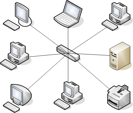
A star network is an implementation of a spoke–hub distribution paradigm in computer networks. In a star network, every host is connected to a central hub. In its simplest form, one central hub acts as a conduit to transmit messages.[1] The star network is one of the most common computer network topologies.

Network / Topolgy

[edit]

The hub and hosts, and the transmission lines between them, form a graph with the topology of a star. Data on a star network passes through the hub before continuing to its destination. The hub manages and controls all functions of the network. It also acts as a repeater for the data flow. In a typical network, the hub can be a network switch, Ethernet hub, wireless access point or a router

The star topology reduces the impact of a transmission line failure by independently connecting each host to the hub. Each host may thus communicate with all others by transmitting to, and receiving from, the hub. The failure of a transmission line linking any host to the hub will result in the isolation of that host from all others, but the rest of the network will be unaffected.[2]

The star configuration is commonly used with twisted pair cable and optical fiber cable. However, it can also be used with coaxial cable as in, for example, a video router.

Advantages and disadvantages

[edit]

Advantages

[edit]
  • If one node or its connection fails, it does not affect the other nodes.[3]
  • Devices can be added or removed without disturbing the network.
  • Works well under heavy load.
  • Appropriate for a large network.

Disadvantages

[edit]
  • Expensive due to the number and length of cables needed to wire each host to the central hub.[3]
  • The central hub is a single point of failure for the network.
  • The number of devices is limited by the capacity of the central hub.

References

[edit]
Revisions and contributorsEdit on WikipediaRead on Wikipedia
from Grokipedia
A star network, also known as a star topology, is a fundamental computer networking configuration in which each individual node or endpoint device connects directly to a central hub, switch, or concentrator via dedicated links, creating a star-like structure that facilitates communication across the network. This topology supports point-to-point connections between the central node and peripherals, enabling full-duplex transmission over guided media such as unshielded (UTP) cable or fiber optics, or even unguided media like signals in modern implementations. One of the defining strengths of the star network lies in its simplicity and scalability for local area networks (LANs): adding or removing nodes requires minimal disruption, as changes are isolated to the central connection, and fault detection is straightforward since issues typically affect only a single link rather than the entire system. Centralized management through the hub or switch allows for efficient traffic control, broadcasting messages to all nodes or directing them unicast to specific ones, which reduces inter-node delays in smaller setups. However, this design introduces a critical vulnerability—a single point of failure at the central node can halt all network operations, and it demands more cabling than alternatives like bus topologies, potentially increasing costs for larger deployments. Historically, star networks predated more distributed architectures; early computer networks relied on a central host to route all communications among peripheral devices, a model that persisted until innovations like in the late 1960s shifted toward decentralized designs. By the , the star topology gained prominence in Ethernet LANs, evolving from linear bus layouts to address cabling complexity and signal degradation issues, and it remains the dominant standard for wired office and home networks today due to its reliability in moderate-scale environments.

Fundamentals

Definition

A star network is a type of computer network topology in which each individual node, or end device, connects directly to a central device, such as a hub or switch, rather than to each other. While early implementations used hubs, contemporary star networks as of 2025 predominantly employ switches as the central device. This arrangement creates a centralized structure where communication between nodes must pass through the central point, distinguishing it from decentralized topologies. In graph theory terms, the star network corresponds to a star graph, denoted as K1,nK_{1,n}, consisting of one central vertex connected to nn peripheral vertices, with no edges between the peripherals. The follows the hub-and-spoke distribution paradigm, analogous to transportation systems where spokes (peripheral nodes) radiate from a central hub for . Unlike point-to-point connections, which establish direct links between pairs of nodes for dedicated communication paths, the hub-and-spoke model in a routes all traffic via the central device, simplifying cabling but introducing a dependency on the hub. Visually, a star network is represented in diagrams as a central circle or point with straight lines extending radially to outer points symbolizing the connected nodes, providing an intuitive illustration of the 's radial and centralized nature. This topology is widely used in physical implementations, particularly Ethernet-based local area networks (LANs), where end devices link to a central switch via like twisted-pair wires.

Key Characteristics

Network topology refers to the arrangement of various elements—such as nodes, , and devices—in a , which can be described in terms of physical layout (the actual cabling and hardware connections) or logical (how flows regardless of physical wiring). The star network topology is characterized by a hierarchical featuring a single central node connected to multiple peripheral or nodes, with no direct interconnections between the leaf nodes themselves. This design ensures that all communication between peripheral devices must pass through the central node, which acts as a for signals. In traditional hub-based star topologies, the central hub creates a shared medium where all connected devices share the same collision domain, potentially leading to signal collisions and interference similar to those in bus or ring topologies. In contrast, modern switch-based implementations utilize dedicated point-to-point links between the central switch and each peripheral device, eliminating shared media and associated issues such as collisions. These dedicated links in switch-based stars provide isolation for each device, allowing for easier detection and isolation of faults within specific segments. Scalability in star networks is constrained by the port capacity of the central device, such as a hub or switch; for instance, typical fixed-configuration Ethernet switches support 5 to 48 ports, limiting the number of directly connected devices without additional hardware expansion.

Components

Central Hub

In the star network , the central hub serves as the core device to which all end devices connect, facilitating communication by managing within . This central component ensures that signals from peripheral nodes are routed appropriately, maintaining the 's point-to-multipoint . The primary types of central devices include hubs and switches, each offering varying levels of functionality suited to different network scales. Hubs, now legacy devices largely replaced by switches in modern networks as of 2025, function as basic multiport , with passive hubs simply connecting devices without , while active hubs regenerate signals to extend transmission distance and amplify them for reliability. Switches represent the current standard, operating at the to forward frames based on MAC addresses, thereby creating separate collision domains per port and reducing compared to hubs. Key functions of the central hub revolve around signal management and traffic control. In hubs, signal regeneration prevents degradation over distance, and all incoming data is broadcast to every connected port, resulting in a shared where simultaneous transmissions can interfere. Switches, by contrast, learn MAC addresses dynamically and forward frames only to the intended destination port, optimizing bandwidth usage and isolating collisions to individual links. Historically, the use of multiport as central hubs emerged in the with the of Ethernet from bus to star topology, driven by the demand for in 10BASE-T implementations. Capacity in central hubs is influenced by port density, which typically ranges from 4 to 48 ports in standard devices, allowing for small to medium networks, and supported bandwidth speeds such as 10 Mbps, 100 Mbps, or 1000 Mbps Ethernet standards. These factors determine the hub's ability to handle multiple simultaneous connections from end devices without performance bottlenecks.

End Devices

In a star network, end devices serve as the peripheral or leaf nodes that connect exclusively to the central hub, lacking direct interconnections with one another to maintain the topology's structure. These devices rely on the hub for all inter-device communication, positioning them as endpoints in the network. Typical end devices encompass a variety of hardware, including computers such as personal computers and laptops, printers for document output, IoT sensors for , and servers dedicated to tasks like file storage or web hosting. Each functions as a client node, sending and receiving data through dedicated links to the hub without forming connections. End devices connect to the central hub using point-to-point cabling methods, primarily twisted-pair Ethernet cables terminated with RJ-45 connectors for standard local area networks, though fiber optic cables are employed for higher-speed or longer-distance applications, and cables in specific legacy or specialized setups. This dedicated linkage per device simplifies the overall design, as each end device typically requires only a single network interface card (NIC) to interface with the network. The promotes ease of installation, particularly in modern Ethernet-based implementations, where end devices support plug-and-play functionality—allowing straightforward connection to available hub ports without necessitating network reconfiguration or extensive technical intervention. This approach enhances accessibility for adding or replacing devices in environments like home offices or small enterprises.

Operation

Data Flow Process

In a star network, data transmission initiates at the source end device, where the payload is encapsulated into an compliant with the standard, including headers for source and destination MAC addresses. The frame is then transmitted over the dedicated physical link—typically twisted-pair cabling such as Category 5 or higher—to the central hub or switch. This point-to-point connection ensures isolation of each link from others, forming the core path for ingress to the network core. Upon receiving the frame, the central device processes it based on its type. A hub, functioning as a Layer 1 , regenerates and broadcasts the incoming signal indiscriminately to all connected ports, mimicking a shared where multiple devices compete for medium access. In this configuration, the protocol employs with (CSMA/CD) in half-duplex mode: the source device senses the medium before transmitting, detects collisions if they occur during transmission, and backs off using a randomized exponential to retransmit, thereby managing contention on the logical bus created by the hub. In contrast, a switch—a more advanced Layer 2 device—examines the frame's destination against its learned address table (built via source address learning from incoming frames) and forwards the frame to the specific output connected to the destination device, avoiding broadcasts and eliminating shared medium collisions entirely. Switched star networks typically operate in full-duplex mode, as specified in amendments like 100BASE-TX, allowing simultaneous bidirectional data flow on each twisted-pair link without CSMA/CD, since transmit and receive paths are logically separated. The destination device receives, decapsulates, and processes the frame, completing the end-to-end transmission. Bandwidth allocation in star networks is inherently link-specific, with each end device enjoying dedicated capacity on its connection to the central device— for example, up to 100 Mbps per in implementations—while the hub or switch oversees overall traffic management through buffering and queuing to handle bursts and prioritize flows as needed. This structure supports scalable throughput, as the central device's aggregates individual link speeds without imposing a single shared limit beyond its internal capacity.

Failure Handling

In star networks, the central hub serves as a single point of failure, meaning an outage in the hub disconnects all attached end devices from the network, halting communication across the entire topology. Conversely, a failure in an individual end device or its dedicated link impacts only that specific node, leaving the rest of the network operational due to the isolated point-to-point connections. To address the hub's , redundancy mechanisms are commonly implemented, such as dual-homing, which connects critical end devices to a primary and backup hub for seamless switching, or switches that detect failures and automatically reroute traffic to alternate paths using protocols like Rapid Spanning Tree Protocol (RSTP). These options enhance , with RSTP enabling recovery in seconds by reconfiguring redundant links. Diagnostics in star networks benefit from the topology's structure, enabling easy isolation of faults through visual indicators like link LEDs on switch ports—which signal active connections (e.g., ) or errors (e.g., )—or via software that monitors port status and logs events. This allows administrators to identify and address issues at the affected link without disrupting other nodes. Recovery times vary by failure type: replacing a faulty end device or cable typically takes minutes, minimizing impact, while a non-redundant hub failure often requires hours of downtime for hardware replacement or reconfiguration, potentially affecting all users until resolved.

Advantages and Disadvantages

Advantages

One key advantage of the star network topology is its ease of expansion. Adding new nodes requires only connecting a single additional cable to the central hub, without the need for rewiring the entire network or disrupting existing connections. This allows networks to grow incrementally, making it suitable for environments where requirements evolve over time. Another significant benefit is fault isolation, which enhances overall reliability. If a single cable or end device fails, the issue is contained to that specific connection, leaving the rest of the network operational since all communications route through the isolated hub paths. This design prevents a localized from cascading across the , as each node operates independently from the others via dedicated . The hub's role in managing these isolated connections further supports this resilience by enabling quick identification and replacement of faulty components. In terms of performance, star topologies, particularly those using switches as the central hub, minimize data collisions by providing dedicated bandwidth to each connection, allowing for efficient handling of high-traffic loads. Full-duplex communication in switched implementations enables simultaneous sending and receiving without shared medium contention, resulting in higher throughput compared to shared-access designs. Finally, maintenance is simplified through centralized administration at the hub. focuses on the central device and individual links rather than tracing issues across a distributed structure, reducing and operational . This centralized approach facilitates monitoring, configuration changes, and upgrades with minimal impact on end devices.

Disadvantages

One primary disadvantage of the star network topology is the high cost associated with cabling and installation. Each end device requires a dedicated connection to the central hub, necessitating significantly more cable length compared to shared-medium topologies like bus networks. This increased cabling demand elevates material expenses and complicates installation, making star networks more costly overall than linear alternatives. Another critical limitation is the dependency on the central hub, which introduces a . If the hub malfunctions or fails, the entire network becomes inoperable, isolating all connected devices and halting communication across the system. This vulnerability stems from the architecture's reliance on the hub for all data routing, rendering the network fragile to central component issues. Star networks also face scalability constraints due to the hub's limited port capacity and processing capabilities. The number of connectable devices is capped by the available ports on the central hub, restricting network expansion without additional hardware. Furthermore, under heavy traffic loads, the hub can become a bottleneck as it must handle all inter-device communications, potentially degrading throughput and latency for the entire network. Additionally, the extensive wiring required in star topologies can lead to greater space consumption and environmental clutter. The proliferation of individual cables from the hub to each device often results in a more disorganized physical layout compared to topologies with shared media, complicating and in constrained spaces.

Comparisons

With Bus Topology

The star topology employs point-to-point connections from each end device to a central hub or switch, creating a centralized structure that facilitates dedicated communication paths. In contrast, the bus topology relies on a single shared backbone cable, to which all devices connect via taps or T-connectors, forming a linear shared-medium configuration. This fundamental structural difference allows star networks to support easier expansion and without disrupting the entire , whereas bus networks require physical intervention on the common cable for modifications. Performance in star topologies benefits from avoiding signal degradation over extended distances, as each link operates independently without the attenuation issues inherent in a bus's prolonged shared cable. Bus topologies, however, experience delays across the shared medium, which can lead to collisions in contention-based access methods like CSMA/CD, reducing overall efficiency as network size increases. Modern star implementations with switches further mitigate collision risks through full-duplex operation, providing superior bandwidth utilization compared to the half-duplex constraints of traditional bus Ethernet. Regarding fault impact, star topologies isolate failures effectively, where a cable break or device malfunction affects only the connected segment, leaving the rest of the network operational. Bus topologies lack this isolation; a single break in the backbone severs connectivity for all devices beyond the fault point, potentially halting the entire network. This vulnerability contributed to the obsolescence of bus designs following the ratification of the IEEE 802.3i standard for 10BASE-T in 1990, which enabled star-based twisted-pair Ethernet and addressed cabling and reliability limitations of coaxial bus systems. As a result, star topologies have become the preferred choice for contemporary local area networks (LANs), while bus topologies are largely historical.

With Ring Topology

In the star topology, devices are arranged in a radial configuration, with each end device connected directly to a central hub or switch via dedicated links, promoting straightforward expansion and isolation of connections. By comparison, the ring topology organizes devices in a sequential chain, where each node links to precisely two neighbors, creating a continuous loop that encircles the entire network without a central coordinator. This structural difference influences cabling requirements, as star setups demand more wiring to the center but allow easier modifications, whereas rings use less overall cable in a looped path but complicate additions or removals due to the interdependent chaining. Data handling in star networks relies on the central hub for mediation: incoming from a sender are either broadcast to all ports (in hub-based Ethernet) or intelligently switched to the intended recipient (in modern switch implementations), supporting bidirectional flow and reducing contention through techniques like CSMA/CD in early versions or full-duplex in contemporary setups. In ring topologies, data propagates unidirectionally around the loop via token-passing protocols, as seen in IBM's standard, where a circulating control token grants exclusive transmission access to the holding station; the sender attaches data to the token, which travels sequentially until reaching the destination, after which the frame is stripped and an acknowledgment is returned. This method ensures ordered, collision-free access but introduces delays proportional to ring size, unlike the star's more direct, hub-routed paths. Regarding reliability, the star topology's centralized architecture creates a at the hub—if it fails due to power loss or malfunction, all connected devices lose network access, though individual link failures only affect isolated nodes. Ring topologies, while vulnerable to cascading disruptions from a single node or cable break that can halt the entire loop's circulation, often build in to mitigate this; for instance, dual-ring configurations like (FDDI) employ counter-rotating loops, allowing traffic to reroute automatically around faults by reconfiguring the ring logically. Thus, rings can offer inherent fault tolerance in well-designed systems, contrasting the star's dependence on robust central hardware. Efficiency comparisons highlight the star topology's advantages in modern Ethernet implementations, which leverage switching to achieve high data rates—such as 1 Gbps or more—while minimizing latency through parallel, point-to-point communications that scale well without sequential delays. Ring topologies, particularly networks limited to 4 Mbps or 16 Mbps speeds, incur higher latency in expansive setups as tokens must traverse the full loop before returning, leading to reduced throughput under heavy loads and making them less suitable for bandwidth-intensive environments compared to the star's flexible, high-speed or switching.

Applications

In Wired Networks

The star network topology has been the primary configuration for Ethernet local area networks (LANs) since the introduction of 10BASE-T in the early , utilizing unshielded twisted-pair (UTP) cabling to connect end devices to a central hub or switch. This standard, part of the family, enabled 10 Mbps transmission over Category 3 or higher UTP cables, with each segment limited to 100 meters, forming a point-to-point star arrangement that replaced earlier coaxial bus topologies for improved reliability and ease of installation. Subsequent Ethernet standards, such as 100BASE-TX and 1000BASE-T, built on this foundation, supporting higher speeds over enhanced UTP categories while maintaining the star structure for twisted-pair implementations. In office and home environments, star networks facilitate systems where horizontal cabling runs from rooms to wall outlet ports, with all connections terminating at central switches for simplified management and scalability. These setups adhere to ANSI/TIA-568 standards, which specify a hierarchical star topology for commercial buildings, ensuring consistent performance for voice, data, and video applications across multiple floors or rooms. In residential settings, a similar approach connects devices like computers and smart home appliances directly to a central router or switch via UTP Ethernet cables, providing straightforward expansion without disrupting existing wiring. Enterprise applications extend star topology to data centers, where access-layer switches in a star configuration interconnect server farms, allowing high-density connections for compute and storage resources. This design supports IEEE 802.3-compliant Ethernet over twisted-pair cabling, enabling efficient traffic aggregation from hundreds of servers to core infrastructure while minimizing cabling complexity in rack-based deployments.

In Wireless Networks

In wireless networks, the star topology is adapted through the use of wireless access points (WAPs) that serve as central hubs, particularly in IEEE 802.11 Wi-Fi standards operating in infrastructure mode. Here, the WAP functions similarly to a wired switch or hub, coordinating communications over radio frequencies rather than physical cables, allowing multiple client devices such as laptops, smartphones, and IoT sensors to connect wirelessly to a single point. Client devices in this setup associate with a single WAP, forming a star-like structure where each "spoke" represents a link from the client to the central AP, emulating the point-to-point connections of traditional wired star networks but using radio signals instead. This association process involves the client scanning for available APs, authenticating, and establishing a secure link, enabling the AP to manage and data to a wired . Common applications include home routers, where a single AP provides coverage for household devices in a basic star configuration. In enterprise wireless area networks (WLANs), multiple APs are deployed and interconnected via a wired core (such as Ethernet switches), creating an extended star topology that scales coverage across large areas like offices or campuses while maintaining centralized management. Key challenges in these wireless star networks involve interference management, as overlapping radio signals from nearby APs or non-Wi-Fi devices (e.g., microwaves or ) can degrade performance through co-channel or , necessitating techniques like channel planning and . Additionally, roaming between APs poses issues in multi-AP environments, where mobile clients may experience delays or disconnections if they cling to a distant AP with weak signal strength instead of seamlessly transitioning to a closer one, often requiring optimizations like 802.11r fast protocols.

References

Add your contribution
Related Hubs
User Avatar
No comments yet.