

Community hub
Recent from talks
Contribute something
Nothing was collected or created yet.
Vortex lift
View on Wikipedia

Vortex lift is that portion of lift due to the action of leading edge vortices.[1] It is generated by wings with highly sweptback, sharp, leading edges (beyond 50 degrees of sweep) or highly-swept wing-root extensions added to a wing of moderate sweep.[2] It is sometimes known as non-linear lift due to its rapid increase with angle of attack[3] and controlled separation lift, to distinguish it from conventional lift which occurs with attached flow.
How it works
[edit]Vortex lift works by capturing vortices generated from the sharply swept leading edge of the wing. The vortex, formed roughly parallel to the leading edge of the wing, is trapped by the airflow and remains fixed to the upper surface of the wing. As the air flows around the leading edge, it flows over the trapped vortex and is pulled in and down to generate the lift.
A straight, or moderate sweep, wing may experience, depending on its airfoil section, a leading-edge stall and loss of lift, as a result of flow separation at the leading edge[4] and a non-lifting wake over the top of the wing. However, on a highly-swept wing leading-edge separation still occurs but instead creates a vortex sheet that rolls up above the wing producing spanwise flow beneath. Flow not entrained by the vortex passes over the top of the vortex and reattaches to the wing surface.[5] The vortex generates a high negative pressure field on the top of the wing. Vortex lift increases with angle of attack (AOA) as seen on lift~AOA plots which show the vortex, or unattached flow, adding to the normal attached lift as an extra non-linear component of the overall lift.[6] Vortex lift has a limiting AoA at which the vortex bursts or breaks down.
Applications
[edit]Four basic configurations which have used vortex lift are, in chronological order, the 60-degree delta wing; the ogive delta wing with its sharply-swept leading edge at the root; the moderately-swept wing with a leading-edge extension, which is known as a hybrid wing; and the sharp-edge forebody, or vortex-lift strake.[7] Wings which generate vortex lift have been used on delta-winged research aircraft such as the Convair XF-92A and Fairey Delta 2. Early delta wing fighters such as the F-102, the F-106, and contemporaries such as Dassault's deltas had cambered leading edges that were blunt and did not generate significant vortexes. The Concorde supersonic airliner had sharp leading edges. Wings with vortex lift over the inboard section are the moderate-sweep wings with an easily identified LERX used on high-manoeuvrability combat aircraft, such as the Northrop F-5 and McDonnell Douglas F/A-18 Hornet. Vortex lift sharp forebody strakes are used on the General Dynamics F-16 Fighting Falcon.
-
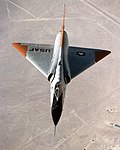
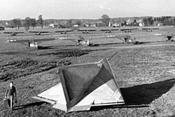 Lippisch DM-1 test glider, 64-degree delta which demonstrated vortex lift in wind tunnel when modified with sharp leading edge at NASA Langley Research Center in 1946
 -
 F-106, a 60-degree delta: an early example with leading edge flow separation
 -
 Concorde showing its ogive delta wing with high sweep angle at wing root: a highly developed shape with controlled flow separation
 -
 Northrop F-5 a wing with moderate sweep: an early application of vortex lift using a LERX
 -
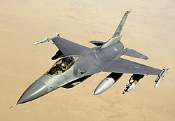 General Dynamics F-16 Fighting Falcon vortices from sharp-edged wide forebody stabilize flow over entire aircraft including outboard wing


Benefits and shortcomings
[edit]Vortex lift provides high lift with increasing AoA at landing speeds and in manoeuvring flight. A high AoA needed to meet landing requirements has, in the past, restricted pilot visibility and led to design complications to accommodate a drooping nose, as in the case of the Fairey Delta 2 and Concorde. For moderate swept wings the addition of a LERX reduces wave drag and improves turning performance and enables a far wider range of flying attitudes.[8] The use of vortex lift is restricted by vortex breakdown or bursting and an inherent instability in yaw. There is considerable drag due to increased lift production and loss of leading edge suction that is part of normal attached flow round a leading edge.[9]
Among animals
[edit]Animals such as hummingbirds, and bats that eat pollen and nectar, are able to hover. They produce vortex lift with the sharp leading edges of their wings and change their wing shapes and curvatures to create stability in the lift.[10]
See also
[edit]References
[edit]- ^ Aircraft Performance and Design, John D. Anderson, Jr., Tata McGraw-Hill Edition 2010,ISBN 978 0 07 070245 5, p.100
- ^ "Why's And Wherefore's Of Wings", B.R.A. Burns, Air International magazine, February 1979, p.82
- ^ Polhamus, E. C. (December 1966). "NASA Technical Reports Server (NTRS)" (PDF). Ntrs.nasa.gov. Retrieved 2020-11-02.
- ^ Design For Air Combat, Ray Whitford 1987, ISBN 0 7106 0426 2, p.16
- ^ NASA TM X 2626
- ^ Design For Air Combat, Ray Whitford 1987, ISBN 0 7106 0426 2, Fig.81
- ^ Design For Air Combat, Ray Whitford 1987, ISBN 0 7106 0426 2, Fig.87
- ^ Design For Air Combat, Ray Whitford 1987, ISBN 0 7106 0426 2, p.89-91
- ^ "The behaviour and performance of leading-edge Vortex flaps" (PDF). Retrieved 2023-12-17.
- ^ "Leading Edge Vortex Allows Bats to Stay Aloft, Aerospace Professor Reports". USC Viterbi School of Engineering. 29 February 2008. Archived from the original on 20 October 2018. Retrieved 9 October 2017.