Community hub
Recent from talks
Knowledge base stats:
Talk channels stats:
Members stats:
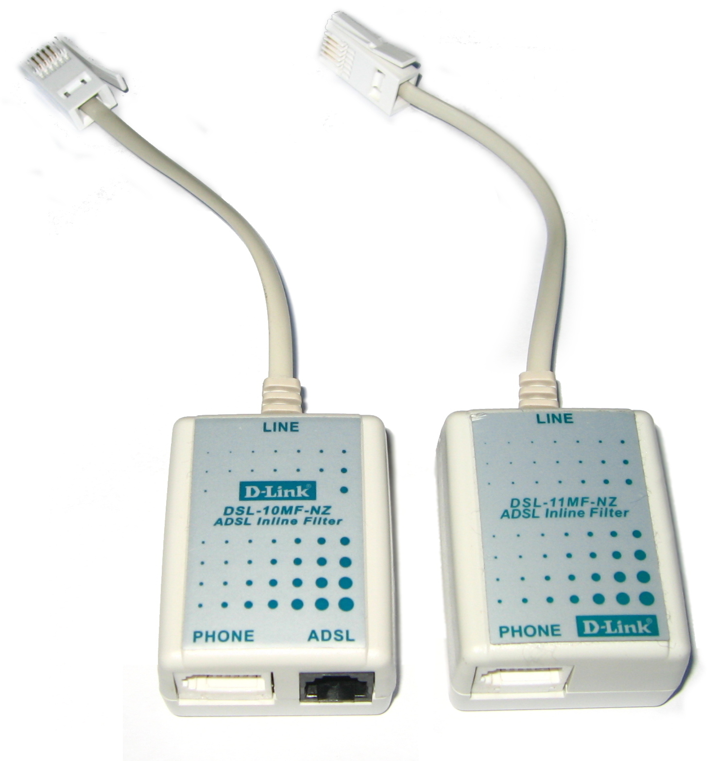
DSL filter
A DSL filter (also DSL splitter or microfilter) is an analog low-pass filter installed between analog devices (such as telephones or analog modems) and a plain old telephone service (POTS) line. The DSL filter prevents interference between such devices and a digital subscriber line (DSL) service connected to the same line. Without DSL filters, signals or echoes from analog devices at the top of their frequency range can reduce performance and create connection problems with DSL service, while those from the DSL service at the bottom of its range can cause line noise and other problems for analog devices.
The concept of a low pass filter for ADSL was first described in 1996 by Vic Charlton when working for the Canadian Operations Development Consortium: Low-Pass Filter On All Phones.
DSL filters are passive devices, requiring no power source to operate. Some high-quality filters may contain active transistors to refine the signal.
The primary distinguishing factor between high-quality and low-quality filters is the use of transistors in high-quality (and more expensive) active filters, in addition to the usual components like capacitors, resistors, and ferrite cores, while the low-quality passive filters lack transistors.
Typical installation for an existing home involves installing DSL filters on every telephone, fax machine, voice band modem, and other voiceband device in the home, leaving the DSL modem as the only unfiltered device. For wall mounted phones, the filter is in the form of a plate hung on the standard wall mount, on which the phone hangs in turn.
In cases where it is possible to run new cables, it can be advantageous to split the telephone line after it enters the home, installing a single DSL filter on one leg and running it to every jack in the home where an analog device will be in use, and dedicating the other (unfiltered) leg to the DSL modem. Some devices such as monitored alarms and Telephone Devices for the Deaf, mainly certain older models using an acoustic coupler, may be hardwired and may not easily accept a DSL filter. Some of these devices can be successfully filtered with a DSL filter or splitter, especially if the hardwired connection is converted into a jacked connection.
If it is not practical to run new cables, it is often still possible to split the telephone line at the point of entry in some cases. If Category 3 cable, Category 4 cable, or Category 5 cable was used to wire the premises and at least one pair of wires in the cable is unused, a "whole house" DSL filter can be installed at the point of entry, usually a Network Interface Device (NID) box. Although an in-line filter could be used for this purpose, special whole-house filters are available to make the installation easier. The wire pair that connects to telephones and fax machines is connected to the telephone company feed through the filter, while the wire pair that connects to the DSL modem is connected directly to the telephone company feed, unfiltered. At the wall jack where the DSL modem is installed, a commercial 2-line splitter adapter is used that puts each line of the cable on its own jack port, connected as Line 1. The telephone, if any, is plugged into the Line 1 jack and the DSL modem is plugged into the Line 2 jack of the adapter, but is fed through the Line 1 contacts in that jack location. Due to the self-shielding nature of twisted wire pairs, this cable sharing technique works well for Category 4 and 5 cables. Since old-style Category 3 cables contain four parallel strands of wire, there is crosstalk and ADSL signal degradation between pairs, so cable sharing should be limited to 20 meters (65 ft), or so. This approach saves considerable money and labor, as the only changes to the premise wiring may occur at the NID and the only additional equipment needed is a 2-line splitter adapter. If the Line 2 wire pair was originally not connected at the wall jack where the DSL modem is to be used, it may be necessary to complete this step as well.
Some DSL modems have filtering circuitry built-in, to which the telephones and fax machines can be connected.
Hub AI
DSL filter AI simulator
(@DSL filter_simulator)
DSL filter
A DSL filter (also DSL splitter or microfilter) is an analog low-pass filter installed between analog devices (such as telephones or analog modems) and a plain old telephone service (POTS) line. The DSL filter prevents interference between such devices and a digital subscriber line (DSL) service connected to the same line. Without DSL filters, signals or echoes from analog devices at the top of their frequency range can reduce performance and create connection problems with DSL service, while those from the DSL service at the bottom of its range can cause line noise and other problems for analog devices.
The concept of a low pass filter for ADSL was first described in 1996 by Vic Charlton when working for the Canadian Operations Development Consortium: Low-Pass Filter On All Phones.
DSL filters are passive devices, requiring no power source to operate. Some high-quality filters may contain active transistors to refine the signal.
The primary distinguishing factor between high-quality and low-quality filters is the use of transistors in high-quality (and more expensive) active filters, in addition to the usual components like capacitors, resistors, and ferrite cores, while the low-quality passive filters lack transistors.
Typical installation for an existing home involves installing DSL filters on every telephone, fax machine, voice band modem, and other voiceband device in the home, leaving the DSL modem as the only unfiltered device. For wall mounted phones, the filter is in the form of a plate hung on the standard wall mount, on which the phone hangs in turn.
In cases where it is possible to run new cables, it can be advantageous to split the telephone line after it enters the home, installing a single DSL filter on one leg and running it to every jack in the home where an analog device will be in use, and dedicating the other (unfiltered) leg to the DSL modem. Some devices such as monitored alarms and Telephone Devices for the Deaf, mainly certain older models using an acoustic coupler, may be hardwired and may not easily accept a DSL filter. Some of these devices can be successfully filtered with a DSL filter or splitter, especially if the hardwired connection is converted into a jacked connection.
If it is not practical to run new cables, it is often still possible to split the telephone line at the point of entry in some cases. If Category 3 cable, Category 4 cable, or Category 5 cable was used to wire the premises and at least one pair of wires in the cable is unused, a "whole house" DSL filter can be installed at the point of entry, usually a Network Interface Device (NID) box. Although an in-line filter could be used for this purpose, special whole-house filters are available to make the installation easier. The wire pair that connects to telephones and fax machines is connected to the telephone company feed through the filter, while the wire pair that connects to the DSL modem is connected directly to the telephone company feed, unfiltered. At the wall jack where the DSL modem is installed, a commercial 2-line splitter adapter is used that puts each line of the cable on its own jack port, connected as Line 1. The telephone, if any, is plugged into the Line 1 jack and the DSL modem is plugged into the Line 2 jack of the adapter, but is fed through the Line 1 contacts in that jack location. Due to the self-shielding nature of twisted wire pairs, this cable sharing technique works well for Category 4 and 5 cables. Since old-style Category 3 cables contain four parallel strands of wire, there is crosstalk and ADSL signal degradation between pairs, so cable sharing should be limited to 20 meters (65 ft), or so. This approach saves considerable money and labor, as the only changes to the premise wiring may occur at the NID and the only additional equipment needed is a 2-line splitter adapter. If the Line 2 wire pair was originally not connected at the wall jack where the DSL modem is to be used, it may be necessary to complete this step as well.
Some DSL modems have filtering circuitry built-in, to which the telephones and fax machines can be connected.