

Recent from talks
Deflection (engineering)
Knowledge base stats:
Talk channels stats:
Members stats:
Deflection (engineering)
In structural engineering, deflection is the degree to which a part of a long structural element (such as beam) is deformed laterally (in the direction transverse to its longitudinal axis) under a load. It may be quantified in terms of an angle (angular displacement) or a distance (linear displacement). A longitudinal deformation (in the direction of the axis) is called elongation.
The deflection distance of a member under a load can be calculated by integrating the function that mathematically describes the slope of the deflected shape of the member under that load. Standard formulas exist for the deflection of common beam configurations and load cases at discrete locations. Otherwise methods such as virtual work, direct integration, Castigliano's method, Macaulay's method or the direct stiffness method are used. The deflection of beam elements is usually calculated on the basis of the Euler–Bernoulli beam equation while that of a plate or shell element is calculated using plate or shell theory.
An example of the use of deflection in this context is in building construction. Architects and engineers select materials for various applications.
Beams can vary greatly in their geometry and composition. For instance, a beam may be straight or curved. It may be of constant cross section, or it may taper. It may be made entirely of the same material (homogeneous), or it may be composed of different materials (composite). Some of these things make analysis difficult, but many engineering applications involve cases that are not so complicated. Analysis is simplified if:
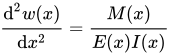
In this case, the equation governing the beam's deflection () can be approximated as: where the second derivative of its deflected shape with respect to ( being the horizontal position along the length of the beam) is interpreted as its curvature, is the Young's modulus, is the area moment of inertia of the cross-section, and is the internal bending moment in the beam.



If, in addition, the beam is not tapered and is homogeneous, and is acted upon by a distributed load , the above expression can be written as:

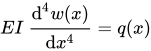
This equation can be solved for a variety of loading and boundary conditions. A number of simple examples are shown below. The formulas expressed are approximations developed for long, slender, homogeneous, prismatic beams with small deflections, and linear elastic properties. Under these restrictions, the approximations should give results within 5% of the actual deflection.
Cantilever beams have one end fixed, so that the slope and deflection at that end must be zero.
Hub AI
Deflection (engineering) AI simulator
(@Deflection (engineering)_simulator)
Deflection (engineering)
In structural engineering, deflection is the degree to which a part of a long structural element (such as beam) is deformed laterally (in the direction transverse to its longitudinal axis) under a load. It may be quantified in terms of an angle (angular displacement) or a distance (linear displacement). A longitudinal deformation (in the direction of the axis) is called elongation.
The deflection distance of a member under a load can be calculated by integrating the function that mathematically describes the slope of the deflected shape of the member under that load. Standard formulas exist for the deflection of common beam configurations and load cases at discrete locations. Otherwise methods such as virtual work, direct integration, Castigliano's method, Macaulay's method or the direct stiffness method are used. The deflection of beam elements is usually calculated on the basis of the Euler–Bernoulli beam equation while that of a plate or shell element is calculated using plate or shell theory.
An example of the use of deflection in this context is in building construction. Architects and engineers select materials for various applications.
Beams can vary greatly in their geometry and composition. For instance, a beam may be straight or curved. It may be of constant cross section, or it may taper. It may be made entirely of the same material (homogeneous), or it may be composed of different materials (composite). Some of these things make analysis difficult, but many engineering applications involve cases that are not so complicated. Analysis is simplified if:
In this case, the equation governing the beam's deflection () can be approximated as: where the second derivative of its deflected shape with respect to ( being the horizontal position along the length of the beam) is interpreted as its curvature, is the Young's modulus, is the area moment of inertia of the cross-section, and is the internal bending moment in the beam.
If, in addition, the beam is not tapered and is homogeneous, and is acted upon by a distributed load , the above expression can be written as:
This equation can be solved for a variety of loading and boundary conditions. A number of simple examples are shown below. The formulas expressed are approximations developed for long, slender, homogeneous, prismatic beams with small deflections, and linear elastic properties. Under these restrictions, the approximations should give results within 5% of the actual deflection.
Cantilever beams have one end fixed, so that the slope and deflection at that end must be zero.
Recent media