Recent from talks
Explorer 38
Knowledge base stats:
Talk channels stats:
Members stats:
Explorer 38
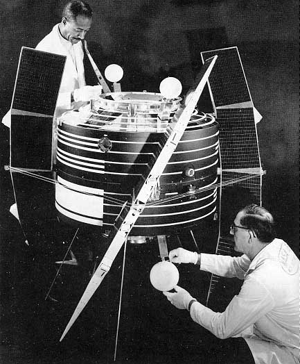
Explorer 38 (also called as Radio Astronomy Explorer A, RAE-A and RAE-1) was the first NASA satellite to study Radio astronomy. Explorer 38 was launched as part of the Explorer program, being the first of the 2 RAE satellites. Explorer 38 was launched on 4 July 1968 from Vandenberg Air Force Base, California, with a Delta J launch vehicle.
Explorer 38 spacecraft measured the intensity of celestial radio sources, particularly the Sun, as a function of time, direction and frequency (0.2 to 20-MHz). The spacecraft was gravity-gradient stabilized. The spacecraft weight was 602 kg (1,327 lb) and average power consumption was 25 watts. It carried two 230 m (750 ft) long V-antennas, one facing toward the Earth and one facing away from the Earth. A 37 m (121 ft) long dipole antenna was oriented tangentially with respect to the Earth's surface.
The spacecraft was also equipped with one 136-MHz telemetry turnstile. The onboard experiments consisted of four step-frequency Ryle-Vonberg radiometers operating from 0.45 to 9.18-MHz, two multichannel total power radiometers operating from 0.2 to 5.4-MHz, one step frequency V-antenna impedance probe operating from 0.24 to 7.86-MHz, and one dipole antenna capacitance probe operating from 0.25 to 2.2-MHz. Explorer 38 was designed for a 12 months minimum operating lifetime.
The spacecraft tape recorder performance began to deteriorate after 2 months in orbit. In spite of several cases of instrument malfunction, good data were obtained on all three antenna systems. The small satellite observed for months the "radio sky" in frequencies between 0.2 and 9.2-MHz, but it was subjected to the continuous radio interference coming from the Earth, both natural (aurorae, thunderstorms) and artificial.
Explorer 38 has 4 antennas deployed in orbit:
The scientific experiments are:
Determine reactive and resistive components of antenna impedance as a function of local electron density, electron temperature, magnetic field, and vehicle potential. The impedance measurements was made at 10 frequencies (0.25 to 8-MHz).
Determine reactive and resistive components of antenna impedance as a function of local electron density, electron temperature, magnetic field, and vehicle potential. The impedance measurements was made at ten frequencies (0.25 to 8-MHz).
Hub AI
Explorer 38 AI simulator
(@Explorer 38_simulator)
Explorer 38
Explorer 38 (also called as Radio Astronomy Explorer A, RAE-A and RAE-1) was the first NASA satellite to study Radio astronomy. Explorer 38 was launched as part of the Explorer program, being the first of the 2 RAE satellites. Explorer 38 was launched on 4 July 1968 from Vandenberg Air Force Base, California, with a Delta J launch vehicle.
Explorer 38 spacecraft measured the intensity of celestial radio sources, particularly the Sun, as a function of time, direction and frequency (0.2 to 20-MHz). The spacecraft was gravity-gradient stabilized. The spacecraft weight was 602 kg (1,327 lb) and average power consumption was 25 watts. It carried two 230 m (750 ft) long V-antennas, one facing toward the Earth and one facing away from the Earth. A 37 m (121 ft) long dipole antenna was oriented tangentially with respect to the Earth's surface.
The spacecraft was also equipped with one 136-MHz telemetry turnstile. The onboard experiments consisted of four step-frequency Ryle-Vonberg radiometers operating from 0.45 to 9.18-MHz, two multichannel total power radiometers operating from 0.2 to 5.4-MHz, one step frequency V-antenna impedance probe operating from 0.24 to 7.86-MHz, and one dipole antenna capacitance probe operating from 0.25 to 2.2-MHz. Explorer 38 was designed for a 12 months minimum operating lifetime.
The spacecraft tape recorder performance began to deteriorate after 2 months in orbit. In spite of several cases of instrument malfunction, good data were obtained on all three antenna systems. The small satellite observed for months the "radio sky" in frequencies between 0.2 and 9.2-MHz, but it was subjected to the continuous radio interference coming from the Earth, both natural (aurorae, thunderstorms) and artificial.
Explorer 38 has 4 antennas deployed in orbit:
The scientific experiments are:
Determine reactive and resistive components of antenna impedance as a function of local electron density, electron temperature, magnetic field, and vehicle potential. The impedance measurements was made at 10 frequencies (0.25 to 8-MHz).
Determine reactive and resistive components of antenna impedance as a function of local electron density, electron temperature, magnetic field, and vehicle potential. The impedance measurements was made at ten frequencies (0.25 to 8-MHz).
Recent media