
Community hub
Recent from talks
Contribute something
Nothing was collected or created yet.
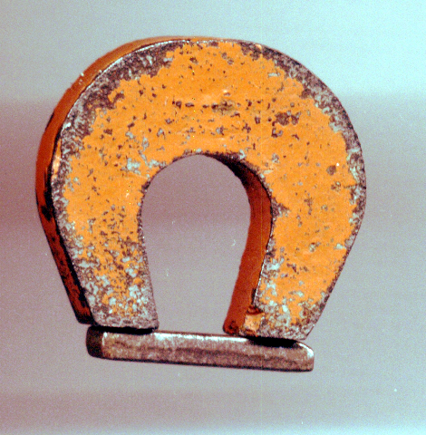
Magnet keeper
View on WikipediaThis article needs additional citations for verification. (January 2019) |

A magnet keeper, also known historically as an armature, is a bar made from magnetically soft iron or steel, which is placed across the poles of a permanent magnet to help preserve the strength of the magnet by completing the magnetic circuit; it is important for magnets that have low magnetic coercivity, such as alnico magnets (0.07T).[1]
Keepers also have a useful safety function, as they restrict external metal from being attracted to the magnet.[clarification needed] Many magnets do not need a keeper, such as neodymium magnets, as they have very high coercivities; only those with low coercivities, meaning that they are more susceptible to stray fields, require keepers.
A magnet can be considered as the sum of many small magnetic domains, which may be only a few microns or smaller in size. Each domain carries its own small magnetic field, which can point in any direction. When all the domains are pointing in the same direction, the fields add up, yielding a strong magnet. When these all point in random directions, they cancel each other, and the net magnetic field is zero.
In magnets with low coercivities, the direction in which the magnetic domains are pointing is easily swayed by external fields, such as the Earth's magnetic field or the stray fields caused by flowing currents in a nearby electrical circuit. Given enough time, such magnets may find their domains randomly oriented, and hence their net magnetization greatly weakened. A keeper for low-coercivity magnets is just a strong permanent magnet that keeps all the domains pointing the same way and realigns any that have gone astray.
References
[edit]- ^ "Permanent Magnets". hyperphysics.phy-astr.gsu.edu.
This electromagnetism-related article is a stub. You can help Wikipedia by adding missing information. |