
Community hub
Recent from talks
Contribute something
Nothing was collected or created yet.
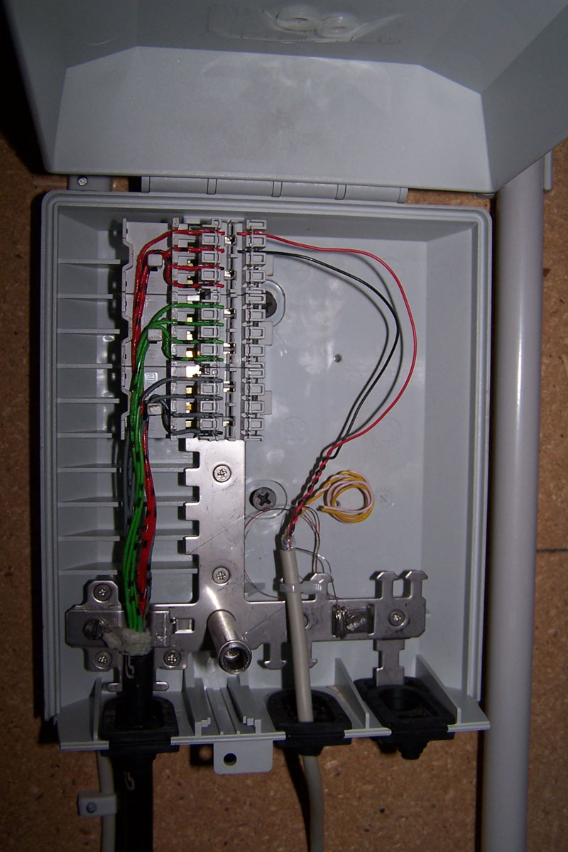
Network interface device
View on WikipediaThis article includes a list of general references, but it lacks sufficient corresponding inline citations. (June 2010) |


In telecommunications, a network interface device (NID; also known by several other names) is a device that serves as the demarcation point between the carrier's local loop and the customer's premises wiring. Outdoor telephone NIDs also provide the subscriber with access to the station wiring and serve as a convenient test point for verification of loop integrity and of the subscriber's inside wiring.
Naming
[edit]Generically, an NID may also be called a network interface unit (NIU),[1] telephone network interface (TNI), system network interface (SNI), or telephone network box.
Australia's National Broadband Network uses the term network termination device or NTD.
A smartjack is a type of NID with capabilities beyond simple electrical connection, such as diagnostics.
An optical network terminal (ONT) is a type of NID used with fiber-to-the-premises applications.
Wiring termination
[edit]The simplest NIDs are essentially just a specialized set of wiring terminals. These will typically take the form of a small, weather-proof box, mounted on the outside of the building. The telephone line from the telephone company will enter the NID and be connected to one side. The customer connects their wiring to the other side. A single NID enclosure may contain termination for a single line or multiple lines.
In its role as the demarcation point (dividing line), the NID separates the telephone company's equipment from the customer's wiring and equipment. The telephone company owns the NID and all wiring up to it. Anything past the NID is the customer's responsibility. To facilitate this, there is typically a test jack inside the NID. Accessing the test jack disconnects the customer premises wiring from the public switched telephone network and allows the customer to plug a "known good" telephone into the jack to isolate trouble. If the telephone works at the test jack, the problem is the customer's wiring, and the customer is responsible for repair. If the telephone does not work, the line is faulty and the telephone company is responsible for repair.
Most NIDs also include "circuit protectors", which are surge protectors for a telephone line. They protect customer wiring, equipment, and personnel from any transient energy on the line, such as from a lightning strike to a utility pole.
Simple NIDs are "dumb" devices, as they contain no digital logic. They have no capabilities beyond wiring termination, circuit protection, and providing a place to connect test equipment.
Smartjack
[edit]
Several types of NIDs provide more than just a terminal for the connection of wiring. Such NIDs are colloquially called smartjacks or Intelligent Network Interface Devices (INIDs) as an indication of their built-in "intelligence", as opposed to a simple NID, which is just a wiring device. Smartjacks are typically used for more complicated types of telecommunications service, such as T1 lines. Plain old telephone service lines generally cannot be equipped with smartjacks.
Despite the name, most smartjacks are much more than a simple telephone jack. One common form for a smartjack is a printed circuit board with a face plate on one edge, mounted in an enclosure.
A smartjack may provide signal conversion, converting codes and protocols, e.g., framing types, to the type needed by the customer equipment. It may buffer and/or regenerate the signal, to compensate for signal degradation from line transmission, similar to what a repeater does.
Smartjacks also typically provide diagnostic capabilities. A very common capability provided by a smartjack is loopback, such that the signal from the telephone company is transmitted back to the telephone company. This allows the company to test the line from the central telephone exchange, without the need to have test equipment at the customer site. The telephone company usually has the ability to remotely activate loopback, without even needing personnel at the customer site. When looped back, the customer equipment is disconnected from the line.
Additional smartjack diagnostic capabilities include alarm indication signal, which reports trouble at one end of the line to the far end. This helps the telephone company know if trouble is present in the line, the smartjack, or customer equipment. Indicator lights to show configuration, status, and alarms are also common.
Smartjacks typically derive their operating power from the telephone line, rather than relying on premises electrical power, although this is not a universal rule.
Optical network terminals
[edit]
In fiber-to-the-premises systems, the signal is transmitted to the customer premises using optical fiber technologies. Unlike many conventional telephone technologies, this does not provide power for premises equipment, nor is it suitable for direct connection to customer equipment. An optical network terminal (ONT, an ITU-T term), also known as an optical network unit (ONU, an IEEE term), is used to terminate the optical fiber line, demultiplex the signal into its component parts (voice telephone, television, and Internet access), and provide power to customer telephones. If the device combines all these services into one it is known as an IAD. As the ONT must derive its power from the customer premises electrical supply, many ONTs have the option for a battery backup in order to maintain service in the event of a power outage or it will go in alarm mode if disconnected and customer may be notified of this.[2] These terminals are used in both active optical networks and passive optical networks. Typically, an ONT connects via a fiber-optic cable to an OLT to complete a connection. An ONT can work in Single Family Unit/SFU mode (modem/bridge) or Home Gateway Unit/HGU mode (router). In passive optical networks, Management is provided by the OLT via OMCI, in case of a GPON connection, and OAM in case of a EPON connection. Authentication and encryption is done via LOID for EPON and PLOAM password, GPON serial number or others for GPON.
Environmental conditions
[edit]According to Telcordia GR-49 requirements for telecommunications, NIDs vary based on three categories of environmental conditions:[3]
- Normal conditions: This refers to a normal environment that is expected in most areas of any service provider. Temperatures are expected to be in the range of −20 to 32 °C (−4 to 90 °F), and humidity is expected to be less than 90% RH. No unusual contamination is expected.
- Severe climatic conditions: These cover environments more severe than those of a normal environment (i.e., higher humidity, high lightning activity, exposure to salt-laden atmosphere, and exposure to contaminants). Temperatures are expected to be in the range of −40 to 43 °C (−40 to 109 °F), and humidity may exceed 90% RH. Jacks installed in NIDs in such environments are known to become contaminated and develop low insulation resistances and low dielectric breakdown voltages when subjected to high humidity. These problems can cause noisy lines or even service outages.
- Flooded conditions: These cover areas of a service provider prone to flooding, such as in coastal or flood plain locations. After a flooding incident, temperature is expected to be in the range of 4.5 to 38 °C (40 to 100 °F), and humidity may exceed 90% RH. The requirements are not to determine if the NID will function during a flood, but to review the ability of the NID to function after the flood has subsided.
Service providers must decide which condition best suits their application.
See also
[edit]Citations
[edit]- ^ "network interface device". Federal Standard 1037C. United States: National Telecommunications and Information Administration. 1996-08-23.
- ^ "What is an Optical Network Terminal (ONT)?". Verizon Communications, Inc. Archived from the original on 2012-10-06.
- ^ GR-49-CORE Generic Requirements for Outdoor Telecommunication Network Interface Devices (NIDs), Telcordia.
General references
[edit]- "Network Interface Device". Verizon Communications, Inc. Archived from the original on 2016-09-15. Retrieved 2009-06-03.
- "Network Interface Device (NID) V9.0". Qwest Communications International. Retrieved 2009-06-03.
- "Functional Criteria for the DS1 Interface Connector" (PDF). BellSouth. June 1993. Archived (PDF) from the original on 2022-10-09. Retrieved 2009-06-03.
- "Testing, Repairing and Installing Home telephone Wiring – Network Interface Device". Public Service Commission of Wisconsin. Archived from the original on 2009-05-11. Retrieved 2009-06-03.
- "Checking the service at the Optical Network Terminal (ONT)". Verizon Communications, Inc. Retrieved 2009-06-03.