Hubbry Logo
66 block66 blockMain
Open search
66 block
Community hub
66 block
logo
8 pages, 0 posts
0 subscribers
Be the first to start a discussion here.
66 block
66 block
from Wikipedia
A split 50 M-type 66 block with bridging clips attached

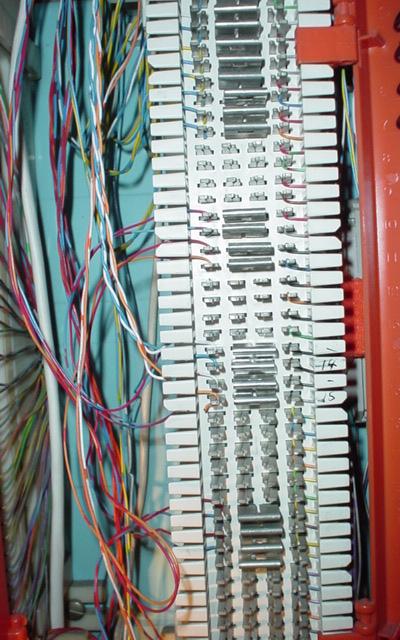
A 66 block is a type of punch-down block used to connect sets of wires in a telephone system. Due to the proliferation of Voice over IP (VoIP), 66 blocks are slowly becoming obsolete.

66 blocks are designed to terminate 20 through 24 AWG insulated solid copper wire.[1] The 66 series connecting block, introduced in the Bell System in 1962, was the first terminating device with insulation displacement connector technology.[citation needed] The term 66 block reflects its Western Electric model number.[2]

66 E blocks are available pre-assembled with an RJ-21 female connector that accepts a quick connection to a 25-pair cable with a male end. These connections are typically made between the block and the customer-premises equipment (CPE).

Types

[edit]

66 blocks are manufactured in four common configurations: A, B, E and M.[a] The A blocks have 25 slotted holes on the left side for positioning the incoming building cable with a 50 slot fanning strip on the right side for distribution cables. The B and M styles have 50 slot fanning strip on both sides. The B style is used mainly in distribution panels where several destinations (often 1A2 key telephones) need to connect to the same source. The M blocks are often used to connect a single instrument to such a distribution block. The E style has five columns of ten 2-clip rows and are used for transitioning from the 25-pair distribution cable to a 25-pair RJ21 style female ribbon connector.

The 25-pair standard non-split 66 block contains 50 rows; each row has two (E) or four (M) or six (A) and (B) columns of clips that are electrically bonded. The 25-pair split 50 66 block is the industry standard for easy termination of voice cabling, and is a standard network termination by telephone companies—generally on commercial properties. Each row contains four (M) or six (B) clips, but the left-side clips are electrically isolated from the right-side clips. Smaller versions also exist with fewer rows for smaller-scale use, such as residential.

Use

[edit]
66 block B series with 6 clips in each row. Jumper wires on the left connect the top pair with the bottom pair, allowing to split up to 10 devices.

Circuit pairs are connected to the block with a punch-down tool by terminating the tip wire on the leftmost slot of one row and ring wire on the leftmost slot of the row beneath. Typically, a 25-pair cable coming from the phone company is punched down on the left side of a split-type block in pairs. The right hand side of the block is wired to the customer premises equipment with jumper wires. Bridging clips are used to connect the two center terminals, connecting the left-hand side of a split block with its right-hand side, thus completing the circuit. The clips form the point of interface between the subscriber and the provider. The bridging clips can be easily removed by either the subscriber or phone company personnel for trouble isolation, allowing the ability to split a circuit and determine in which direction trouble may exist. An orange insulating cover attached to a 66 block denotes its designation as a demarcation point by the local exchange carrier.[citation needed]

Modern 110 blocks have largely supplanted 66 blocks for new commercial installations at the end of the 20th century, as the capability for a circuit to carry digital data overlaid its ability to carry analog voice conversations. 110 block termination is almost always compliant with Category 5 (or higher) and therefore capable of supporting 100 MHz (or faster) signaling. Compared to 110 and higher-density wire terminating blocks, 66 blocks are physically large; and because of their maximum 16 MHz Category 3 signaling compatibility, they are ill-suited for high speed (faster than 10BASE-T) data circuits.

Split 50 66 blocks are still used as network interface blocks in distribution frames to interconnect circuits with bridging clips, but are primarily limited to narrowband circuits such as POTS/DSL, DS0, or DS1 circuits.

See also

[edit]
  • 25-pair color code – Form of color code used in wiring
  • RJ21 – Often used as a connector for pre-terminated 66 blocks

Notes

[edit]

References

[edit]
Revisions and contributorsEdit on WikipediaRead on Wikipedia
from Grokipedia
A 66 block, also known as a 66-style wiring block, is a used in to terminate and cross-connect multi-pair twisted-pair cables for voice, , and systems. It consists of rows of insulation displacement connectors (IDCs), typically providing 50 fixed positions for 22-26 AWG solid insulated wire, allowing secure, gas-tight connections via a punch-down tool without the need to strip insulation. Developed during the era when analog telephony dominated organizational communications, the 66 block became ubiquitous for organizing wiring in central offices and customer premises, enabling quick cross-connections between equipment like private branch exchanges (PBX) and endpoint devices. Constructed from high-impact, fire-retardant UL 94V-0 plastic with clips, it supports Category 5e performance standards, including compliance with ANSI/TIA-568.2-D for horizontal cabling and reduced near-end crosstalk (NEXT) through specialized clip designs. Commonly wall-mounted or secured to backboards in entrance facilities and rooms using 89D-style brackets, 66 blocks facilitate with integrated fanning strips and labeling options, promoting efficient reconfiguration and maintenance. While it has been largely replaced by more modular 110-style blocks in contemporary data networking due to greater flexibility for Ethernet applications, the 66 block persists in legacy installations and high-density voice environments for its reliability and cost-effectiveness.

History

Origins and development

The 66 block was developed by in the early 1960s as part of the 66 series of connecting blocks, representing a significant advancement in wiring infrastructure. This innovation introduced the first insulation displacement connector (IDC) technology within the , enabling reliable connections without the need for stripping wire insulation. The IDC mechanism, building on earlier cold-welding principles from the era, utilized forked slots to pierce insulation and form gas-tight electrical contacts, addressing the growing demands of expanding networks. This IDC design was based on US Patent 3,012,219, issued in 1961 to William J. Henn. The naming of the 66 block derives directly from Western Electric's internal model designation, "type 66," which was assigned to this series of punch-down terminals. Introduced in , it succeeded earlier models like the type 65 connecting block and was specifically engineered to manage the vast volumes of wiring required in central office telephone exchanges. Prior to its development, traditional screw terminals were the standard for wire terminations, but these methods were labor-intensive, prone to over time, and inefficient for high-density installations, often requiring hours per connection and risking intermittent faults due to loose contacts. Initially purposed for cross-connecting pairs of 22- to 26-gauge solid copper wires in analog telephone systems, the 66 block facilitated flexible rearrangements and maintenance in voice circuits, supporting the Bell System's push toward scalable, modular telephony infrastructure. Its design emphasized durability and ease of reconfiguration, allowing technicians to jumper lines quickly with bridging clips, which proved essential for the era's transmission over twisted-pair cabling.

Adoption in telecommunications

The 66 block achieved widespread adoption within the , including and its regional operating companies, during the for central office and private branch exchange (PBX) installations. Its design allowed for efficient termination and cross-connection of hundreds of wire pairs, supporting the expanding demands of analog telephone networks at the time. This scalability made it a staple in large-scale setups, where quick reconfiguration of circuits was essential for service providers. Standardization efforts in the late 1980s and early 1990s by the (EIA) and (TIA) formalized the 66 block's specifications, ensuring across telecom equipment. These standards defined compatibility with 22-26 AWG solid copper wire, suitable for typical cabling, and incorporated bridging clips to electrically connect adjacent terminals for flexible circuit routing. Such guidelines facilitated consistent deployment in voice infrastructure, reinforcing the block's role as an industry benchmark. In the , the 66 block evolved to accommodate emerging data applications, achieving Category 5e performance ratings under updated TIA/EIA-568 standards. This adaptation, which maintained low through optimized insulation displacement contacts, allowed its continued use in mixed voice and low-speed data environments despite the broader transition to digital telecom systems. Manufacturers like Siemon introduced enhanced versions, such as the S66 series, to meet these requirements while preserving with legacy voice setups. By the post-2000s era, the 66 block saw a decline in new installations, largely supplanted by modular RJ45 jacks and patch panels that better supported high-bandwidth Ethernet and VoIP. However, it persists in legacy systems for maintaining older POTS lines and cross-connects in central offices, where replacement costs outweigh the benefits of modernization.

Design and components

Physical structure

The 66 block is constructed from high-impact, flame-retardant , typically meeting UL 94V-0 standards for fire resistance, ensuring durability in environments. This molded plastic forms a rectangular base that supports IDC terminals, with variations available to accommodate 25, 50, or 100 pairs (via stacking) through different configurations. In the standard 50-pair configuration, the block features a layout of 50 rows, each containing four IDC clips arranged in columns, with slots above each clip for wire insertion and metal contacts positioned beneath for termination. The outer two clips per row are designated for incoming cable terminations, while the inner two support cross-connections, allowing for flexible routing without . The standard 50-pair block measures approximately 10 inches in height, 3.4 inches in width, and 1.2 inches in depth, providing a compact form factor suitable for dense installations. It can be mounted on backboards, walls, or using 89-series brackets for secure attachment in equipment racks or enclosures. Common accessories include labeling strips for pair identification, hinged plastic covers to protect terminations from dust and damage, and mounting brackets that facilitate organized and elevation above surfaces. These elements enhance the block's practicality in professional wiring setups.

Insulation displacement mechanism

The insulation displacement connection (IDC) mechanism in a 66 block enables the termination of insulated wires without the need for stripping, relying on sharp-edged metal contacts to pierce the insulation and establish a direct electrical bond with the conductor. Upon insertion using a punch-down tool, the forked slots in the contacts displace the insulation material laterally while clamping the bare wire under —typically around 15,000 psi—to form a gas-tight, cold-welded connection that resists oxidation and ensures low-resistance without . The contacts themselves are constructed from , often with tin plating to enhance corrosion resistance in humid or industrial environments. These spring-like prongs provide mechanical tension to maintain contact integrity, supporting wire gauges from 22 to 26 AWG and accommodating up to 200 insertion and extraction cycles before potential degradation. Electrically, the IDC design in 66 blocks supports frequencies up to 100 MHz for both voice and low-speed data applications, though performance is optimized for with limitations in due to the block's row-based layout. Crosstalk mitigation occurs through the inherent spacing and alternation in contact positioning across rows, which helps isolate adjacent circuits. For , the mechanism allows reusability by extracting wires with a tool to release the IDC grip, facilitating reconfiguration without full replacement; however, repeated or excessive punching can damage the wire insulation or deform the contact slots, compromising long-term reliability.

Types and variations

Standard configurations

The standard configurations of 66 blocks are defined by their pair capacity, catering to varying scales of telephony and low-voltage wiring needs in telecommunications infrastructure. These blocks typically feature rows of insulation displacement connection (IDC) clips, each row accommodating one pair (tip and ring conductors) via four slots for incoming and outgoing terminations. The 25-pair configuration is a compact variant designed for smaller installations, such as single-line extensions in offices or residential settings. It consists of 25 rows of clips, allowing termination of up to 25 twisted-pair cables, and is often pre-wired with a 25-pair female Telco connector for simplified connectivity in limited-space environments. The 50-pair configuration represents the most widely adopted standard for residential and commercial applications, supporting up to 50 lines in equipment rooms or wiring closets. This block features 50 rows of four IDC clips per row, enabling cross-connections between incoming multi-pair cables and distribution wiring, and is rated for 22-26 AWG solid copper conductors. For larger-scale deployments in multi-tenant buildings or central offices, the 100-pair configuration provides expanded capacity, typically achieved by combining two 50-pair blocks or using a dedicated 100-pair unit with 100 rows of clips. These larger blocks often incorporate quick-connect features, such as integrated protection modules or pre-connectorized Amphenol-style interfaces, to facilitate rapid deployment and maintenance of high-density voice lines. Wiring on all standard 66 block configurations adheres to the color-coding scheme to ensure accurate pair identification and termination. This system organizes 25-pair cables into five color groups—, red, black, yellow, and violet—each with binders and individual pair colors (e.g., blue/-blue for pair 1 in the group), preventing and simplifying troubleshooting in multi-pair installations.

Specialized blocks

Specialized variants of the 66 block have been developed to address specific requirements in and networking, extending beyond the standard configurations for . The M-block and B-block represent key adaptations, with M-blocks designed for higher-density voice cross-connects in equipment rooms and telecom closets, featuring 50-pair capacities and modular adapters for quick reconfiguration. B-blocks, in contrast, are smaller and stackable, supporting 6- to 50-pair setups ideal for PBX cabinets and key telephone installations, providing flexibility in compact spaces without explicit miniaturization but through reduced scale compared to full 25-pair units. Enhanced 66 blocks rated for Category 5e performance meet TIA/EIA-568-A standards up to 100 MHz, offering improved specifications suitable for Ethernet and applications while maintaining compatibility with voice systems. These variants often integrate RJ45 jacks or adapters, such as 8-position configurations, to facilitate modular connections for high-bandwidth needs like 100 Mbps LANs. Some manufacturers produce blocks prewired with multiple RJ45 ports, enabling direct interfacing with modern networking equipment. For outdoor and harsh environments, 66 blocks are housed in sealed enclosures to provide weatherproofing, with IP65-rated options protecting against and ingress during external installations. These adaptations ensure reliability in exposed settings, such as building entrances or remote telecom points, by combining the block's punch-down functionality with robust, UV-resistant or ABS housings. Originally manufactured by as part of the Bell System's hardware in the mid-20th century, production of 66 blocks has shifted to third-party specialists like , ICC, and Siemon. Modern iterations comply with RoHS directives, using flame-retardant, lead-free materials to meet environmental and safety standards for contemporary deployments.

Installation and wiring

Punch-down procedures

The termination of wires into a 66 block utilizes insulation displacement contacts (IDCs) that pierce the wire insulation without requiring stripping, enabling a reliable mechanical and electrical connection. Essential tools for this process include a 66-style impact punch-down tool equipped with a compatible blade for precise insertion and trimming, a wire stripper used minimally only for jacket removal if needed, and a label maker to identify terminations for maintenance. A spudger may also assist in positioning wires. The punch-down procedure begins by preparing the cable: strip 2-3 inches of the outer jacket using the , taking care not to nick the insulation, then untwist the pairs minimally—ideally to 1/2 inch—to preserve . Align the wire with the designated IDC slot on the block, inserting it from the side so that the wire end faces consistently upward or downward across all terminations for uniform tool application. Position the wire at a slight into the slot to ensure proper seating, then use the impact punch-down tool—oriented with the cut side facing the wire tail—to drive the wire firmly into the IDC at a 90-degree to the block; the tool's spring-loaded mechanism will trim excess wire automatically. Repeat for each wire, following the of the intended wiring scheme, such as terminating the white-striped (tip) wire before the solid-colored (ring) wire in each pair. Safety precautions and best practices emphasize controlled force to avoid damaging the IDC or wire: select the low-impact setting on adjustable tools to prevent over-punching, which can deform contacts or conductors, and always punch perpendicularly without angling the tool to maintain contact integrity. Wear safety glasses to protect against flying wire fragments, and ensure all wires are labeled immediately after termination for . Remove any trimmed wire stubs promptly to prevent shorts. Post-installation testing verifies the terminations through continuity checks: use a multimeter set to continuity mode, attaching probes or clips to each pair's terminals on the block to confirm low resistance (typically under 5 ohms) and no opens or between pairs. should confirm secure seating without loose strands.

Common wiring schemes

Common wiring schemes on a 66 block typically involve terminating incoming lines on the top rows and extensions or outgoing lines on the bottom rows, with connections made between them using bridge clips or short jumper wires to facilitate cross-connections. This arrangement allows for organized distribution of pairs, where the top two rows handle central or incoming feeds, and the bottom two rows manage station wiring or extensions, enabling easy bridging across the block's center terminals without permanent . Punch-downs are performed vertically into the insulation displacement contacts (IDCs) for each row, ensuring wires enter from the top or bottom uniformly to maintain tension and avoid cross-talk. Bridging techniques rely on metal clips for temporary or semi-permanent splits and solid wire wraps for more durable cross-connections. Bridge clips, often U-shaped pieces about half an inch long, snap onto the center slots of adjacent terminals in the same row, electrically linking the left and right sides of a split 66 block to complete circuits for multiple devices. For non-adjacent connections, short jumper wires are punched into the inner terminals and routed to the desired rows, providing flexibility for custom routing while minimizing interference. These methods support quick reconfiguration, such as isolating faults by removing a clip, which is essential in cross-connect frames. The scheme is applied to identify tip and ring conductors systematically across the block's rows. In this standard, pairs are grouped by major colors (, red, black, yellow, violet) combined with minor colors (, orange, green, brown, slate), starting with pair 1 as white- (tip: with blue stripe, ring: solid ) and progressing to pair 25 as violet-slate. Tip conductors (positive polarity) are punched down first into the left-side "A" terminals, followed by ring conductors (negative polarity) into the right-side "B" terminals, row by row from top to bottom, ensuring consistent polarity and pair integrity for up to 25 lines per block side. For DSL and POTS applications, a 66 block can connect to an external splitter device that separates the incoming DSL/POTS signal into voice and data outputs using frequency separation (POTS below 4 kHz, DSL above 25 kHz). The central office line is terminated on one row, with jumpers or bridges routing the splitter's POTS output to rows for voice extensions and the DSL output to rows for the modem, often dedicating distinct pairs to avoid interference.

Applications

Traditional telephony

The 66 block served as a fundamental component in traditional , primarily functioning as a punch-down termination and cross-connect point for distributing (POTS) lines from central offices and private branch exchanges (PBX) to building extensions. In central offices, these blocks were deployed in arrays within wiring closets to manage incoming trunks and subscriber loops, with configurations supporting hundreds of pairs to accommodate large-scale voice traffic distribution. Similarly, in PBX environments, 66 blocks enabled the organized routing of multiple lines, allowing technicians to punch down incoming cables on one side and jumper connections to internal wiring on the other for reliable signal transfer. Within key telephone systems, common in small to medium offices during the analog era, 66 blocks provided the backbone for interconnecting multi-line telephones and setups. These systems relied on the block's modular clips to distribute shared lines across extensions, supporting features like call holding and transferring without complex switching equipment. The design's flexibility allowed for quick reconfiguration, making it ideal for dynamic office environments where line assignments changed frequently. Compatibility with legacy equipment further solidified the 66 block's role, as it supported direct connections to wall jacks via Universal Service Ordering Code (USOC) wiring standards. Terminations followed color-coded pairs—typically blue for the first line—to interface with RJ11 jacks for single-line POTS or RJ14 for dual-line applications, ensuring plug-and-play integration with standard analog phones and peripherals.

Modern and alternative uses

In contemporary applications, 66 blocks have been adapted for networking, particularly in legacy systems where Cat5e-rated variants can be used for low-speed transmissions. These blocks serve as punch-down terminals for terminating twisted-pair cabling in environments requiring simple, high-density wire management, such as older setups or temporary network extensions, though they are not recommended for high-speed Ethernet due to performance limitations. For and systems, 66 blocks are commonly employed to terminate wires and connect them to remote units (RTUs) via 25-pair cables, facilitating contact-closure monitoring for up to 24 points plus ground. Bridging clips on the blocks allow for easy of circuits, enabling isolation of specific s for or segmented monitoring in commercial buildings. This setup provides a reliable between field wiring and control panels, often pre-wired for quick integration with RTUs like the NetGuardian series. In audio and video distribution, 66 blocks find use in low-voltage installations for multi-pair runs to speakers or systems, where insulation displacement connections (IDC) accommodate 22-26 AWG solid wire for efficient termination. They are particularly suited to older and paging systems, distributing signals across building zones without the need for modular jacks, though stranded wire requires solid-core adapters for secure connections. Despite the prevalence of RJ45 patch panels in modern infrastructure, 66 blocks retain relevance in the for rural and legacy , including transitions from fiber optics to distribution where they interface optical network terminals (ONTs) with existing POTS lines or hybrid setups. Their durability and ease of cross-connection continue to support voice and low-voltage applications in areas with slower upgrade cycles.

Advantages and limitations

Key benefits

The 66 block offers significant cost-effectiveness in wiring due to its low material cost, making it an economical choice for large-scale deployments. Additionally, its insulation displacement connection (IDC) design eliminates the need for or wire stripping, which substantially reduces labor time compared to traditional screw terminals by enabling quick, tool-efficient terminations. In terms of scalability, the 66 block supports high pair densities, accommodating up to 50 pairs in a compact form factor that is ideal for extensive installations, such as in equipment rooms or wiring closets. Its modular bridging clips allow for straightforward reconfiguration and cross-connections without disrupting existing wiring, facilitating easy expansions or modifications in growing networks. The durability of 66 blocks is a key strength, with IDC connections forming gas-tight, cold-welded bonds that resist , , and oxidation, ensuring long-term reliable performance in demanding telecom environments. These connections maintain integrity without mechanical loosening, outperforming screw terminals in long-term stability. Installation simplicity further enhances its efficiency, as the process requires only a basic punch-down tool, making it accessible to technicians without advanced specialized training. This user-friendly approach minimizes tooling changes and supports rapid deployment, even for multiple wires simultaneously.

Drawbacks and alternatives

Despite their historical utility in , 66 blocks have several limitations that restrict their use in contemporary applications. They perform poorly at frequencies above 16 MHz (Category 3 rating), primarily due to elevated and , which render them unsuitable for high-speed data transmission such as . Additionally, their relatively bulky design—featuring multiple rows of IDC terminals—can be problematic in space-constrained environments like modern data centers or compact wiring closets. Safety concerns further compound these issues. 66 blocks present a risk of electrical shock when working with live circuits, if the block is not covered or insulated during installation and . Moreover, 66 blocks are optimized for solid-conductor wire (typically 22-26 AWG) and perform poorly with stranded wire, which can lead to loose connections and unreliable terminations due to the IDC mechanism's design. Common alternatives address these shortcomings effectively. The , for instance, supports higher data rates up to 500 MHz with superior mitigation and , making it a standard choice for Category 5e and higher cabling in data networks. Modular patch panels provide greater flexibility for Ethernet deployments, allowing quick reconfigurations without punch-down tools and better integration with RJ-45 connectors. In international telephony contexts, Krone (LSA-PLUS) blocks serve as a reliable option, offering IDC terminations compatible with both solid and stranded wire while maintaining compatibility with global standards. Transition trends reflect these limitations, with 66 blocks largely phased out in new VoIP and optic installations since the in favor of patch panels and IDC alternatives. As of 2025, they persist in retrofits for legacy buildings and specific analog applications, where existing infrastructure favors cost-effective adaptations over full replacements.

References

Add your contribution
Related Hubs
User Avatar
No comments yet.