
Community hub
Recent from talks
Contribute something
Nothing was collected or created yet.
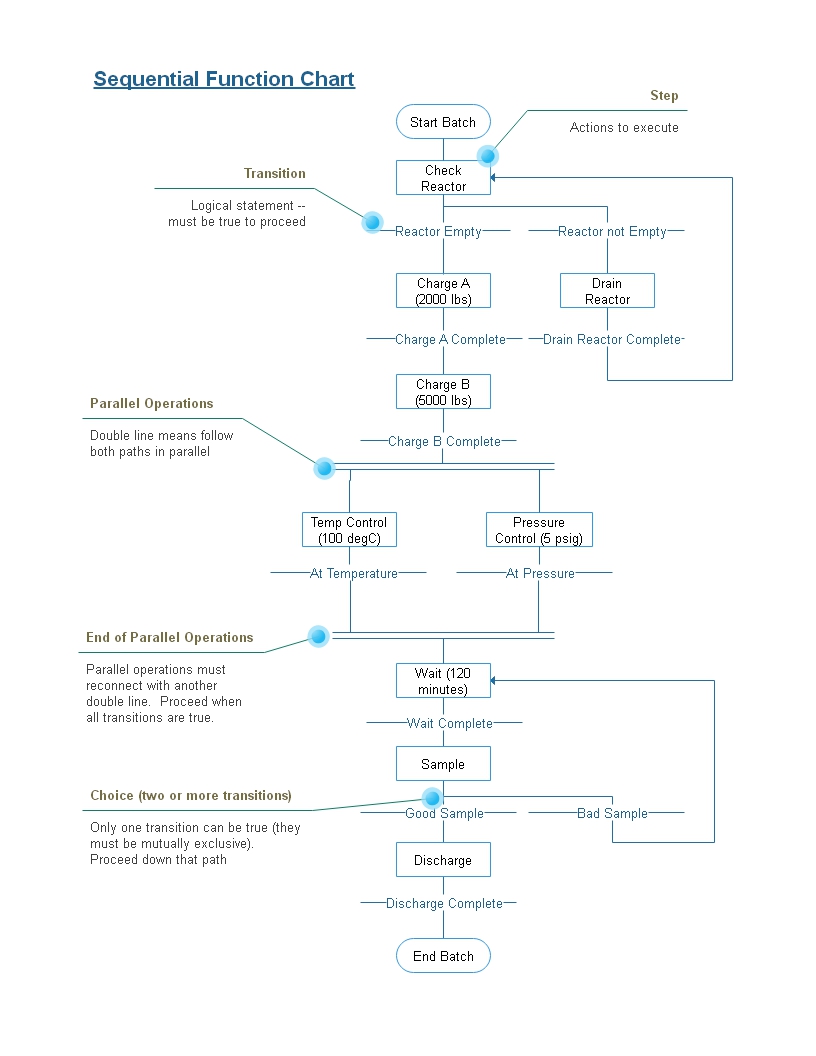
Sequential function chart
View on WikipediaSequential function chart (SFC) is a visual programming language used for programmable logic controllers (PLCs). It is one of the five languages defined by IEC 61131-3 standard. The SFC standard is defined as Preparation of function charts for control systems, and was based on GRAFCET (itself based on binary Petri nets[1][2]).
It can be used to program processes that can be split into steps.

Main components of SFC are:
- Steps with associated actions;
- Transitions with associated logic conditions;
- Directed links between steps and transitions.
Steps in an SFC diagram can be active or inactive. Actions are only executed for active steps. A step can be active for one of two motives:
- It is an initial step as specified by the programmer.
- It was activated during a scan cycle and not deactivated since.
Steps are activated when all steps above it are active and the connecting transition is superable (i.e. its associated condition is true). When a transition is passed, all steps above are deactivated at once and after all steps below are activated at once.
Actions associated with steps can be of several types, the most relevant ones being Continuous (N), Set (S), and Reset (R). Apart from the obvious meaning of Set and Reset, an N action ensures that its target variable is set to 1 as long as the step is active. An SFC rule states that if two steps have an N action on the same target, the variable must never be reset to 0. It is also possible to insert LD (Ladder Diagram) actions inside an SFC program (and this is the standard way, for instance, to work on integer variables).
SFC is an inherently parallel programming language in that multiple control flows — Program Organization Units (POUs) in the standard's parlance — can be active at once.
Non-standard extensions to the language include macroactions: i.e. actions inside a program unit that influence the state of another program unit. The most relevant such macroaction is "forcing", in which a POU can decide the active steps of another POU.[3]
See also
[edit]- DRAKON-chart
- UML activity diagram
- Continuous Function Chart
References
[edit]- ^ Fernandez, J. L.; Sanz, R.; Paz, E.; Alonso, C. (19–23 May 2008). "Using hierarchical binary Petri nets to build robust mobile robot applications: RoboGraph". IEEE International Conference on Robotics and Automation, 2008. Pasadena, CA, USA. pp. 1372–1377. doi:10.1109/ROBOT.2008.4543394.
- ^ Lewis, R. W. (1998). Programming industrial control systems using IEC 1131-3. ISBN 978-0852969502.
- ^ Tom Meadowcroft, 2018
External links
[edit]Sequential function chart
View on GrokipediaOverview
Definition and Purpose
A Sequential Function Chart (SFC) is a graphical programming language standardized in IEC 61131-3 for programmable logic controllers (PLCs), offering a visual method to represent the sequential behavior of control systems in industrial automation. It employs a structured set of graphical and equivalent textual elements to model the progression of operations over time, enabling engineers to depict how processes evolve through defined phases and conditions. This approach facilitates the organization of complex logic within programs and function blocks, particularly for machines and process plants where orderly execution is critical.[10] The primary purpose of SFC is to specify and manage the logical flow of activities in discrete or batch manufacturing processes, allowing for the decomposition of intricate control problems into manageable, sequential components. By providing a clear depiction of execution order, SFC simplifies the design, verification, and maintenance of automation systems, reducing errors in scenarios involving timed or conditional operations. It is especially valuable for applications requiring predictable behavior, such as assembly lines or chemical processing, where understanding the chronological sequence enhances system reliability and debuggability.[11][12] At its core, SFC operates as an adapted form of state-transition diagrams tailored for industrial control, focusing on the temporal and conditional advancement of system states to ensure synchronized execution. This conceptualization builds upon earlier flowchart-like techniques, evolving to address the non-deterministic and parallel aspects inherent in modern automation tasks, thereby supporting more robust process modeling under the IEC 61131-3 framework.[13][10]Relation to IEC 61131-3
IEC 61131-3 serves as the international standard for programming languages used in programmable controllers, first published by the International Electrotechnical Commission (IEC) in 1993, with subsequent editions including the third in 2013 and the fourth in May 2025.[10] This standard specifies the syntax and semantics of a unified suite of four programming languages to facilitate consistent implementation across programmable logic controllers (PLCs).[10] Within IEC 61131-3, Sequential Function Chart (SFC) is defined as one of the three graphical programming languages, alongside Ladder Diagram (LD) and Function Block Diagram (FBD), complemented by the textual language Structured Text (ST).[10] SFC's graphical nature allows for visual representation of sequential control processes, distinguishing it from the more continuous or logic-oriented graphical languages like LD and FBD.[4] By mandating precise syntax and semantics for SFC, IEC 61131-3 ensures that programs developed in this language are portable across compliant PLC vendors and systems, reducing vendor-specific dependencies and enhancing interoperability in industrial automation.[10] The standard requires SFC implementations to support hierarchical structures for decomposing complex control problems into sub-charts and parallel branches to enable simultaneous execution of multiple sequences, which is essential for modeling intricate processes like batch operations.[14]History
Origins in Grafcet
The Sequential Function Chart (SFC) traces its roots to Grafcet, a graphical formalism developed in France for specifying and analyzing sequential control systems in manufacturing processes. Grafcet, standing for GRAphe Fonctionnel de Commande Étape/Transition, was introduced in 1977 by a working group under the French Association for Economic and Technical Cybernetics (AFCET). This group, comprising around 40 researchers and industrial practitioners who had been convening since 1975, aimed to create a standardized method for describing logical automatisms in discrete event systems, particularly to facilitate the design of programmable logic controllers (PLCs) in industrial automation.[15][16] A core innovation of Grafcet was its use of steps to represent operational states and transitions to denote conditions for moving between states, forming a bipartite graph that clearly delineates sequential behavior. This approach directly addressed the shortcomings of traditional relay-based ladder diagrams, which, while effective for simple combinational logic, struggled to intuitively model complex sequences, parallel branches, and state-dependent actions without becoming unwieldy. By emphasizing a structured, flowchart-like visualization, Grafcet enabled engineers to specify control logic more declaratively, reducing ambiguity in requirements capture and implementation for manufacturing sequences like assembly lines or batch processes.[17] During the 1980s, Grafcet gained international traction, particularly in Europe, where it was implemented in automation systems, including PLC software from French and German vendors, promoting its use in sectors like automotive and chemical processing. Grafcet was formalized as the French standard NF C 03-190 in 1982 and later as the international IEC 60848 in 1988, solidifying its role in sequential control design.[18][19] SFC emerged as the direct successor to Grafcet within the IEC 61131-3 standard for PLC programming languages, adopted in 1993, incorporating Grafcet's foundational elements with minor adaptations for broader compliance and interoperability. Key changes included the standardization of action qualifiers—such as non-stored (N), set (S), and pulse (P)—to precisely define how actions associate with steps, ensuring consistent execution semantics across diverse PLC vendors while retaining Grafcet's graphical essence. These refinements made SFC more suitable for global industrial application without altering the core step-transition paradigm.[20][21]Standardization
The Sequential Function Chart (SFC) was formally incorporated into the international standard IEC 61131-3 as part of its first edition, published in December 1993, which harmonized the graphical notation derived from Grafcet to support global interoperability in programmable logic controller (PLC) programming languages.[22] The second edition of IEC 61131-3, released in 2003, extended capabilities across the languages, including SFC, by adding new data types (such as WSTRING), references, namespaces, and additional standard function blocks to enhance modularity in sequential control applications.[23] The third edition, published in 2013, introduced object-oriented programming features such as classes, methods, and interfaces, further refined SFC's execution semantics and error-handling mechanisms while maintaining compatibility with prior versions, including updated definitions for program organization and fault-tolerant operations in industrial environments.[24] The fourth edition, published in May 2025, includes enhancements such as support for UTF-8 strings and other updates to the syntax and semantics of the programming languages, ensuring continued relevance for modern industrial automation while preserving backward compatibility.[10] Development of SFC within IEC 61131-3 was led by the International Electrotechnical Commission (IEC) Technical Committee 65 (TC 65) on Industrial-process measurement, control, and automation, specifically through its Subcommittee 65B, ensuring syntactic alignment with other standardized languages like Ladder Diagram and Function Block Diagram for consistent PLC implementation across vendors.[25] Major vendors have adopted SFC in compliance with IEC 61131-3; for instance, Siemens' STEP 7 environment implements SFC via its GRAPH editor, supporting standard elements for sequential program structuring with extensions for advanced diagnostics.[26][27] Similarly, Rockwell Automation's Studio 5000 integrates SFC for Logix controllers, providing IEC 61131-3-compliant routines for state-based control with features like concurrent branches and transition conditions.[28][29]Elements of SFC
Steps
In Sequential Function Charts (SFCs) standardized by IEC 61131-3, a step serves as the core state-holding element, depicted as a rectangular box that represents an active state during which associated actions are performed to control the process.[30][1] Steps are categorized into three primary types to facilitate structured sequential control. The initial step, declared using theINITIAL_STEP keyword, acts as the entry point of the SFC, becoming active immediately upon program initialization, with exactly one such step required per chart.[30] Normal steps, defined with the STEP keyword, denote subsequent states in the sequence following the initial activation.[30] Macro steps introduce hierarchy by encapsulating a self-contained subsequence of steps and transitions, enabling modularity and reuse to simplify complex diagrams without invoking separate subprograms.[31]
Key properties of steps include their binary state—active when executing actions or inactive otherwise—and the ability to monitor duration since activation via an associated time variable.[30] Enabling conditions for a step are established by the evaluation of incoming transitions, ensuring controlled progression through the chart.[30]
Per IEC 61131-3 visual notation, steps are rendered as solid rectangles, each optionally annotated with a unique name and sequential number for clarity and reference.[1] This notation extends to parallel steps, which allow representation of concurrent operations through branching, supporting multifaceted process control.