Single-mode optical fiber
Main page
2312515

Single-mode optical fiber

logo
Community Hub0 subscribers
Read side by side
from Wikipedia

The structure of a typical single-mode fiber:
  1. Core 8–9 μm diameter
  2. Cladding 125 μm diameter
  3. Buffer 250 μm diameter
  4. Jacket 900 μm diameter

In fiber-optic communication, a single-mode optical fiber, also known as fundamental- or mono-mode,[1] is an optical fiber designed to carry only a single mode of light - the transverse mode. Modes are the possible solutions of the Helmholtz equation for waves, which is obtained by combining Maxwell's equations and the boundary conditions. These modes define the way the wave travels through space, i.e. how the wave is distributed in space. Waves can have the same mode but have different frequencies. This is the case in single-mode fibers, where we can have waves with different frequencies, but of the same mode, which means that they are distributed in space in the same way, and that gives us a single ray of light. Although the ray travels parallel to the length of the fiber, it is often called transverse mode since its electromagnetic oscillations occur perpendicular (transverse) to the length of the fiber. The 2009 Nobel Prize in Physics was awarded to Charles K. Kao for his theoretical work on the single-mode optical fiber.[2] The standards G.652 and G.657 define the most widely used forms of single-mode optical fiber.[3]

History

[edit]

In 1961, Elias Snitzer while working at American Optical published a comprehensive theoretical description of single mode fibers in the Journal of the Optical Society of America.[4][5]

At the Corning Glass Works (now Corning Inc.), Robert Maurer, Donald Keck and Peter Schultz started with fused silica, a material that can be made extremely pure, but has a high melting point and a low refractive index. They made cylindrical preforms by depositing purified materials from the vapor phase, adding carefully controlled levels of dopants to make the refractive index of the core slightly higher than that of the cladding, without raising attenuation dramatically. In September 1970, they announced they had made single-mode fibers with attenuation at the 633-nanometer helium-neon line below 20 dB/km.[6]

Characteristics

[edit]

Unlike multi-mode optical fiber, single-mode fiber does not exhibit modal dispersion. This is due to the fiber having such a small cross section that only the first mode is transported. Single-mode fibers are therefore better at retaining the fidelity of each light pulse over longer distances than multi-mode fibers. For these reasons, single-mode fibers can have a higher bandwidth than multi-mode fibers. Equipment for single-mode fiber is more expensive than equipment for multi-mode optical fiber, but the single-mode fiber itself is usually cheaper in bulk. [citation needed]

Cross section of a single-mode optical fiber patch cord end, taken with a fiberscope. The outermost circle is the cladding, 125 μm in diameter. Debris is visible as a streak on the cross-section, and glows due to the illumination.

A typical single-mode optical fiber has a core diameter between 8 and 10.5 μm[7] and a cladding diameter of 125 μm. There are a number of special types of single-mode optical fiber which have been chemically or physically altered to give special properties, such as dispersion-shifted fiber and nonzero dispersion-shifted fiber. Data rates are limited by polarization mode dispersion and chromatic dispersion. As of 2005, data rates of up to 10 gigabits per second were possible at distances of over 80 km (50 mi) with commercially available transceivers (Xenpak). By using optical amplifiers and dispersion-compensating devices, state-of-the-art DWDM optical systems can span thousands of kilometers at 10 Gbit/s, and several hundred kilometers at 40 Gbit/s.[citation needed]

The lowest-order bounds mode is ascertained for the wavelength of interest by solving Maxwell's equations for the boundary conditions imposed by the fiber, which are determined by the core diameter and the refractive indices of the core and cladding. The solution of Maxwell's equations for the lowest order bound mode will permit a pair of orthogonally polarized fields in the fiber, and this is the usual case in a communication fiber.

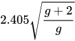
In step-index guides, single-mode operation occurs when the normalized frequency, V, is less than or equal to 2.405. For power-law profiles, single-mode operation occurs for a normalized frequency, V, less than approximately

,

where g is the profile parameter.

In practice, the orthogonal polarizations may not be associated with degenerate modes.

OS1 and OS2 are standard 9/125 μm single-mode optical fiber. Both are used with wavelengths 1310 nm and 1550 nm. OS1 has a maximum attenuation of 1 dB/km and OS2 is a maximum of 0.4 dB/km. OS1 is defined in ISO/IEC 11801,[8] and OS2 is defined in ISO/IEC 24702.[9]

Connectors

[edit]

Optical fiber connectors are used to join optical fibers where a connect/disconnect capability is required. The basic connector unit is a connector assembly. A connector assembly consists of an adapter and two connector plugs. Due to the sophisticated polishing and tuning procedures that may be incorporated into optical connector manufacturing, connectors are generally assembled onto optical fiber in a supplier's manufacturing facility. However, the assembly and polishing operations involved can be performed in the field, for example to make cross-connect jumpers to size.

Optical fiber connectors are used in telephone company central offices, at installations on customer premises, and in outside plant applications. Their uses include:

  • Making the connection between equipment and the telephone plant in the central office
  • Connecting fibers to remote and outside plant electronics such as optical network units (ONUs) and digital loop carrier (DLC) systems
  • Optical cross connects in the central office
  • Patching panels in the outside plant to provide architectural flexibility and to interconnect fibers belonging to different service providers
  • Connecting couplers, splitters, and wavelength-division multiplexers (WDMs) to optical fibers
  • Connecting optical test equipment to fibers for testing and maintenance.

Outside plant applications may involve locating connectors underground in subsurface enclosures that may be subject to flooding, on outdoor walls, or on utility poles. The closures that enclose them may be hermetic, or may be "free-breathing". Hermetic closures will prevent the connectors within being subjected to temperature swings unless they are breached. Free-breathing enclosures will subject them to temperature and humidity swings, and possibly to condensation and biological action from airborne bacteria, insects, etc. Connectors in the underground plant may be subjected to groundwater immersion if the closures containing them are breached or improperly assembled.

The latest industry requirements for optical fiber connectors are in Telcordia GR-326, Generic Requirements for Single-Mode Optical Connectors and Jumper Assemblies.

A multi-fiber optical connector is designed to simultaneously join multiple optical fibers together, with each optical fiber being joined to only one other optical fiber.

The last part of the definition is included so as not to confuse multi-fiber connectors with a branching component, such as a coupler. The latter joins one optical fiber to two or more other optical fibers.

Multi-fiber optical connectors are designed to be used wherever quick and/or repetitive connects and disconnects of a group of fibers are needed. Applications include telecommunications companies' central offices (COs), installations on customer premises, and outside plant (OSP) applications.

The multi-fiber optical connector can be used in the creation of a low-cost switch for use in fiber optical testing. Another application is in cables delivered to a user with pre-terminated multi-fiber jumpers. This would reduce the need for field splicing, which could greatly reduce the number of hours necessary for placing an optical fiber cable in a telecommunications network. This, in turn, would result in savings for the installer of such cable.

Industry requirements for multi-fiber optical connectors are covered in GR-1435, Generic Requirements for Multi-Fiber Optical Connectors.

Fiber optic switches

[edit]

An optical switch is a component with two or more ports that selectively transmits, redirects, or blocks an optical signal in a transmission medium.[10] According to Telcordia GR-1073, an optical switch must be actuated to select or change between states. The actuating signal (also referred to as the control signal) is usually electrical, but in principle, could be optical or mechanical. (The control signal format may be Boolean and may be an independent signal; or, in the case of optical actuation, the control signal may be encoded in the input data signal. Switch performance is generally intended to be independent of wavelength within the component passband.)

Quadruply clad fiber

[edit]

In fiber optics, a quadruply clad fiber is a single-mode optical fiber that has four claddings.[11] Each cladding has a refractive index lower than that of the core. With respect to one another, their relative refractive indices are, in order of distance from the core: lowest, highest, lower, higher.

A quadruply clad fiber has the advantage of very low macrobending losses. It also has two zero-dispersion points, and moderately low dispersion over a wider wavelength range than a singly clad fiber or a doubly clad fiber.

Advantages

[edit]

Low Attenuation

[edit]

Single-mode optical fibers exhibit very low signal attenuation, typically around 0.2 dB/km at 1550 nm. This allows for signal transmission over distances exceeding 100 kilometers without the need for electrical repeaters, making them suitable for wide-area and submarine networks. [12]

High Bandwidth and Data Rate Capacity

[edit]

Thanks to single-path light propagation, single-mode fiber avoids modal dispersion entirely. This allows support for extremely high data rates and advanced technologies like dense wavelength-division multiplexing (DWDM), enabling efficient use of fiber infrastructure.[13]

Low Dispersion and High Signal Integrity

[edit]

With a core diameter of approximately 8–10 μm, light travels in a single mode, minimizing modal distortion. Although chromatic dispersion still occurs, it can be compensated using specialized fiber types or signal processing. The result is a high-fidelity signal over long distances.[14]

Scalability for Future Networks

[edit]

Single-mode fibers support high transmission frequencies and are compatible with future optical technologies, making them ideal for long-term infrastructure investment. They are standard in backbone, metro, and data center interconnect networks.[13][15]

Immunity to Interference and Crosstalk

[edit]

The confined propagation of light within a single mode improves signal-to-noise ratio and reduces vulnerability to external interference and crosstalk, particularly in dense network environments.[12]

Disadvantages

[edit]
  • More difficult manufacturing and handling
  • Higher price
  • Difficult coupling of light into the fiber

See also

[edit]

References

[edit]
[edit]
Revisions and contributorsEdit on WikipediaRead on Wikipedia
from Grokipedia
Single-mode optical fiber (SMF) is a type of optical fiber engineered to support the propagation of light in only a single transverse mode, typically the fundamental LP01 mode, per polarization direction, which minimizes signal distortion and enables high-fidelity transmission over extended distances.[1] This design features a narrow core diameter of approximately 8 to 10 micrometers, surrounded by a cladding with a small refractive index difference, typically around 0.35%,[2] facilitating total internal reflection for wavelengths generally above the cutoff wavelength of around 1260 nm.[1] Operating primarily in the near-infrared spectrum (1260–1625 nm), SMF achieves single-mode guidance when the normalized frequency parameter (V-number) is less than 2.405, ensuring a consistent Gaussian-like output beam profile without modal interference.[1] Standardized by the International Telecommunication Union (ITU-T) under Recommendation G.652 (08/2024),[3] single-mode optical fiber encompasses categories such as G.652.A through G.652.D, each optimized for specific performance metrics including attenuation, dispersion, and bend resistance, with the fiber exhibiting zero-dispersion near 1310 nm and low chromatic dispersion in the 1550 nm window for compatibility with erbium-doped fiber amplifiers.[4] Key transmission characteristics include maximum attenuation of 0.4 dB/km at 1310 nm and 0.3 dB/km at 1550 nm for standard categories, alongside mode field diameters of about 9.2 μm at 1310 nm and 10.4 μm at 1550 nm,[3] as exemplified by widely used products like Corning's SMF-28 fiber.[5] Unlike multimode fibers, SMF eliminates intermodal dispersion, resulting in propagation losses as low as 0.16 dB/km at 1550 nm in ultra-low-loss variants[6] and support for bandwidths exceeding multiple gigabits per second without repeaters over distances up to hundreds of kilometers.[1] The primary advantages of single-mode optical fiber lie in its superior capacity for long-haul applications, where it outperforms multimode alternatives by offering higher bandwidth potential (up to terabits per second in wavelength-division multiplexing systems) and reduced signal attenuation, making it immune to the limitations of modal dispersion that restrict multimode fibers to shorter runs.[1] It is extensively deployed in telecommunications infrastructure, including submarine cables, metropolitan area networks, and internet backbones, as well as in high-definition video transmission, military communications, and fiber-optic sensing for structural monitoring and medical imaging.[7] Recent advancements, such as bend-insensitive variants compliant with ITU-T G.657, further enhance its versatility for compact installations in data centers and access networks, while maintaining backward compatibility with legacy G.652 standards.[4]

Fundamentals

Definition and Principles

Single-mode optical fiber is an optical waveguide designed to propagate light in a single transverse mode, enabling low-loss transmission over long distances. It typically features a small core diameter of 8-10 micrometers, optimized for operating wavelengths around 1550 nm, where the fundamental mode is confined primarily within the core.[8] This design distinguishes it from multimode fibers, which support multiple modes and suffer from higher modal dispersion.[8] The guiding mechanism in single-mode optical fiber relies on total internal reflection at the core-cladding interface, where light rays incident from the higher-refractive-index core to the lower-index cladding at angles greater than the critical angle are fully reflected back into the core.[9] Standard single-mode fibers employ a step-index refractive index profile, with an abrupt change in refractive index between the core (n₁) and cladding (n₂, where n₁ > n₂), promoting efficient mode confinement compared to graded-index profiles more common in multimode fibers.[10][8] Single-mode operation is governed by the normalized frequency parameter, or V-number, derived from waveguide theory. The V-number is defined as $ V = \frac{2\pi a}{\lambda} \sqrt{n_1^2 - n_2^2} $, where $ a $ is the core radius, $ \lambda $ is the wavelength, and $ n_1 $ and $ n_2 $ are the core and cladding refractive indices, respectively; the fiber supports only the fundamental mode when $ V < 2.405 $.[11] This condition arises from solving the scalar wave equation in cylindrical coordinates using Bessel functions for the radial field components in the core and modified Bessel functions in the cladding, with boundary continuity yielding the eigenvalue equation whose first root for the LP₀₁ mode is at 2.405.[12] The cutoff wavelength for single-mode propagation is thus $ \lambda_c = \frac{2\pi a}{2.405} \sqrt{n_1^2 - n_2^2} $, above which higher-order modes are not guided.[12]

Mode Propagation and Conditions

In single-mode optical fibers, light propagates primarily in the fundamental linearly polarized mode, denoted as LP01, which is the only guided mode under single-mode conditions. This mode features a Gaussian-like intensity profile with the electric field predominantly confined to the core region, while the evanescent tail extends slightly into the cladding, enabling weak interactions with the surrounding medium. The LP01 mode is radially symmetric and supports two orthogonal polarizations, maintaining approximate linear polarization for weakly guiding fibers with small core-cladding index differences.[13] The single-mode regime is defined by operation at wavelengths longer than the cutoff wavelength λc, beyond which higher-order modes are not guided, ensuring minimal modal dispersion. For standard single-mode fibers, λc is typically below 1260 nm to support operation at 1310 nm and 1550 nm without multimode effects. The zero-dispersion wavelength, around 1310 nm for dispersion-unshifted fibers, marks the point where chromatic dispersion vanishes, influencing system design for low-distortion transmission.[3] Chromatic dispersion in single-mode fibers arises from two main contributions: material dispersion, due to the wavelength-dependent refractive index of silica, and waveguide dispersion, stemming from the fiber's geometry and mode confinement. The total dispersion parameter D, expressed in ps/(nm·km), quantifies the wavelength dependence of the group delay and is given by
D=ddλ(1vg)S(λλ0) D = \frac{d}{d\lambda} \left( \frac{1}{v_g} \right) \approx S (\lambda - \lambda_0)
where vg is the group velocity, S is the dispersion slope (typically ~0.09 ps/(nm²·km)), λ is the operating wavelength, and λ0 is the zero-dispersion wavelength; higher-order terms account for deviations at longer wavelengths. Polarization mode dispersion (PMD), another key impairment, results from birefringence induced by fiber imperfections, bends, or stresses, causing orthogonal polarization components to travel at slightly different group velocities and leading to pulse broadening that scales with the square root of fiber length.[14][15] Attenuation in single-mode fibers primarily stems from Rayleigh scattering, where microscopic density fluctuations in the glass scatter light inversely proportional to the fourth power of the wavelength (α ∝ 1/λ⁴), absorption by residual impurities such as OH ions, and bending losses that radiate guided power into the cladding when the fiber is curved beyond a critical radius. These mechanisms combine to yield a typical minimum loss of 0.2 dB/km at 1550 nm in standard silica fibers, enabling long-haul transmission over hundreds of kilometers.[16][17][18] A key factor in single-mode fiber attenuation is the "water peak," an absorption band around 1383 nm caused by hydroxyl (OH⁻) ions in the glass matrix. In conventional single-mode fibers, this results in elevated loss (often >1 dB/km) in the E-band (1360–1460 nm), limiting usable spectrum. Modern ITU-T G.652.C/D compliant fibers feature low water peak (LWP) or zero water peak (ZWP) designs. LWP ensures attenuation at 1383 nm ≤ that at 1310 nm (typically ≤0.34 dB/km), while ZWP eliminates the peak more completely (0.27–0.31 dB/km), providing lower overall loss and enabling full-spectrum transmission from 1260–1625 nm. This supports advanced multiplexing techniques and longer reach without additional amplification.

Construction and Types

Core-Cladding Structure

Single-mode optical fibers feature a core-cladding structure designed to guide light efficiently over long distances. The core consists of silica glass doped with germanium dioxide (GeO₂) to achieve a higher refractive index (n₁ ≈ 1.468), while the surrounding cladding is made of undoped or pure silica glass with a lower refractive index (n₂ ≈ 1.462). This refractive index contrast, typically on the order of 0.3-0.4%, confines light within the core via total internal reflection.[19][20] For standard single-mode fibers like Corning's SMF-28, the core diameter is precisely 8.2 μm, ensuring single-mode operation at wavelengths around 1310 nm and 1550 nm. The cladding diameter is standardized at 125.0 ± 0.7 μm to facilitate compatibility with connectors and splicing. The numerical aperture (NA), which quantifies the fiber's light-gathering capability, is approximately 0.14 and is calculated as NA = \sqrt{n_1^2 - n_2^2}. Core diameters in the 8-10 μm range are common across standard implementations to balance mode confinement and splice loss.[20][21] The fiber is protected by a dual-layer polymer jacket applied over the cladding. The primary coating is a soft acrylate layer that cushions the glass against mechanical stress and microbends, while the secondary coating is a harder acrylate buffer that enhances handling durability and stripability. The total coating diameter is typically 245 ± 5 μm, providing a robust outer sheath without adding excessive bulk.[20][21] In harsh environments, such as subsea or high-temperature applications, single-mode fibers may incorporate hermetic coatings to resist hydrogen ingress, which can cause attenuation increases. These include a thin carbon or metallic layer (e.g., aluminum) between the cladding and polymer jacket, forming a diffusion barrier against hydrogen, water, and corrosive agents. Corning's hermetic single-mode fibers, for instance, demonstrate attenuation changes of ≤ 0.05 dB/km after hydrogen exposure tests.[22]

Specialized Variants

Dispersion-shifted fibers (DSF) represent a key variant of single-mode optical fiber engineered to relocate the zero-dispersion wavelength from its standard position near 1310 nm to around 1550 nm, aligning with the low-loss window ideal for dense wavelength-division multiplexing (DWDM) in long-haul telecommunications.[23] This shift is achieved through a specialized triangular refractive index profile in the core, where the index increases gradually from the center to the edges before decreasing toward the cladding, optimizing chromatic dispersion characteristics for multi-channel systems. The design minimizes pulse broadening at operating wavelengths, supporting higher data rates, though it requires careful management of nonlinear interactions in dense spectral packing.[24] Non-zero dispersion-shifted fibers (NZDSF) build on the DSF concept by introducing a deliberate small positive or negative dispersion value at 1550 nm—typically 1 to 6 ps/nm·km—while significantly lowering the dispersion slope to values below 0.06 ps/nm²·km.[25] This modification enhances tolerance to nonlinear effects, such as self-phase modulation and four-wave mixing, which are exacerbated in zero-dispersion environments during high-power DWDM transmission.[26] By flattening the dispersion curve across the C-band (1530–1565 nm), NZDSF enables broader channel spacing and improved signal integrity over transoceanic distances without excessive reliance on dispersion compensation modules.[27] Polarization-maintaining fibers are specialized single-mode designs tailored for polarization maintenance, featuring a structure with a central silica core surrounded by a cladding that includes embedded boron- or germanium-doped stress rods positioned symmetrically along orthogonal axes to induce birefringence.[2] The stress rods create thermal expansion mismatches that generate principal stresses, producing high intrinsic birefringence—often exceeding 5 × 10^{-4}—to lock light into specific polarization states and suppress cross-coupling in sensitive environments.[28] This configuration, common in formats like PANDA (polarization-maintaining and absorption-reducing), supports applications in fiber gyroscopes, interferometric sensors, and high-power laser systems where polarization stability is critical.[29] Bend-insensitive fibers, standardized under ITU-T G.657, incorporate modified refractive index profiles, such as trench-assisted or segmented cladding designs, to minimize losses from bending while maintaining single-mode operation and compatibility with standard G.652 fibers. These variants feature a depressed index region around the core to confine the optical mode more tightly, reducing macrobend attenuation to levels below 0.1 dB for bends with radii as small as 7.5 mm at 1550 nm, enabling deployment in tight spaces like access networks and data centers.[30] Photonic crystal fibers (PCF) in their single-mode variants employ a microstructured cladding composed of a periodic lattice of air holes—typically arranged in a hexagonal pattern—surrounding a defect core formed by omitting or enlarging central holes, facilitating guidance via photonic bandgap or modified total internal reflection.[31] This air-hole arrangement enables endless single-mode operation, where the fundamental mode remains confined without higher-order modes across an exceptionally wide wavelength spectrum, from visible to mid-infrared, due to the effective index contrast provided by the porous structure.[32] Such fibers offer tailorable dispersion and nonlinearity properties, making them suitable for supercontinuum generation and advanced nonlinear optics experiments.[33]

History and Development

Early Invention

The origins of single-mode optical fiber trace back to theoretical advancements in the mid-1960s that envisioned low-loss glass waveguides for long-distance communication. In a landmark 1966 paper, Charles K. Kao and George A. Hockham proposed that attenuation in silica-based fibers could be reduced to below 20 dB/km through rigorous purification to eliminate metallic impurities and hydroxyl (OH-) groups responsible for strong absorption. This prediction shifted focus from high-loss cladded glass rods to purified bulk glass, establishing the feasibility of optical fibers as a superior alternative to copper cables, and earned Kao the 2009 Nobel Prize in Physics for groundbreaking achievements in fiber communication. Experimental breakthroughs followed swiftly in the early 1970s, with researchers at Corning Glass Works achieving the first practical low-loss single-mode fiber in 1970. Robert D. Maurer, Donald B. Keck, and Peter C. Schultz developed a fiber with an attenuation of 20 dB/km at 632 nm wavelength, using an inside vapor deposition process involving wet chemistry purification to remove transition metal impurities and minimize OH- absorption peaks around 1.4 μm and beyond. This single-mode design featured a small core (approximately 0.75 μm diameter) surrounded by a pure silica cladding, demonstrating that impurity reduction could enable viable light transmission over kilometer distances.[34] The conceptual development of single-mode propagation advanced through theoretical work in the 1970s, building on waveguide principles to ensure only the fundamental mode could propagate, minimizing modal dispersion. Key contributions came from researchers like Stewart E. Miller, who explored integrated optics applications for fibers, and E.A.J. Marcatili, whose analyses of dielectric waveguides clarified mode confinement in weakly guiding structures with precise refractive index differences between core and cladding. These efforts culminated in 1974 when Bell Laboratories demonstrated the first single-mode fiber transmission experiment, achieving signal propagation over 1.5 km at 1.06 μm wavelength with losses around 1.2 dB/km, using modified chemical vapor deposition for accurate core-cladding fabrication. Overcoming challenges like OH- absorption—peaking due to water contamination in silica—and the need for sub-micron precision in core diameter (typically 5-10 μm) and index contrast (about 0.3%) was essential to confine light effectively and suppress higher-order modes.[35]

Commercialization and Standards

The commercialization of single-mode optical fiber accelerated in the 1980s with key deployments that demonstrated its viability for long-distance telecommunications. A pivotal milestone was the 1988 activation of TAT-8, the first transatlantic fiber-optic submarine cable, which spanned approximately 6,700 km and initially operated at 40 Mbit/s per fiber pair using single-mode technology at 1,300 nm.[36][37] By the mid-1980s, advancements in fiber purity enabled attenuation as low as 0.154 dB/km at 1,550 nm, supporting extended transmission without excessive signal loss.[38] Standardization efforts by the International Telecommunication Union - Telecommunication Standardization Sector (ITU-T) formalized single-mode fiber specifications to ensure interoperability and performance. The G.652 category defines standard single-mode fiber (SMF) optimized for operation around 1,310 nm and 1,550 nm, with parameters including a mode field diameter of 9-10 μm and a maximum polarization mode dispersion (PMD) coefficient of 0.2 ps/√km.[39][40] Complementary standards include G.653 for dispersion-shifted fiber (DSF), which minimizes chromatic dispersion near 1,550 nm to enhance high-bit-rate systems, and G.655 for non-zero dispersion-shifted fiber (NZDSF), designed to balance dispersion for dense wavelength-division multiplexing (DWDM) while avoiding nonlinear effects.[41][42] By the 1990s, single-mode fiber supplanted multimode variants in telecommunications infrastructure, particularly for long-haul applications, as the commercialization of erbium-doped fiber amplifiers (EDFAs) enabled efficient amplification at 1,550 nm and facilitated the rollout of DWDM systems.[43][44] This transition supported exponential growth in network capacity and global connectivity. Post-2000 developments addressed practical deployment challenges, with ITU-T G.657 introducing bend-insensitive single-mode fibers to reduce losses in tight-radius installations common in access networks and fiber-to-the-home (FTTH) setups; initial recommendations emerged around 2006, with categories like G.657.A1 offering maximum macrobend loss of 0.75 dB per turn at 1550 nm for 10 mm radii.[45][46]

Manufacturing Processes

Fiber Drawing

The production of single-mode optical fiber begins with the fabrication of a preform, a cylindrical rod that serves as the precursor for the fiber structure. Common methods include modified chemical vapor deposition (MCVD) and outside vapor deposition (OVD). In MCVD, vapors of silicon tetrachloride (SiCl4) and germanium tetrachloride (GeCl4) are introduced into a rotating silica glass tube, where they react with oxygen to deposit layers of silica (SiO2) and germania (GeO2), forming the core and cladding regions with a core-to-cladding diameter ratio of approximately 1:15. The tube is then heated to collapse it into a solid preform rod. OVD involves depositing soot particles of SiO2 and GeO2 externally onto a ceramic bait rod, which are later consolidated into a preform through high-temperature sintering. These processes ensure the precise refractive index profile required for single-mode propagation, with the core doped with GeO2 to achieve a higher index than the undoped SiO2 cladding. The drawing process transforms the preform into a continuous fiber strand. The preform, typically 20-40 mm in diameter and 1-2 m long, is fed vertically into a high-temperature furnace where it is heated to around 2000°C, softening the silica glass without crystallization. At this point, the softened tip is pulled downward by a tractor or capstan mechanism, elongating the material into a fiber with a standard cladding diameter of 125 μm. Drawing speeds typically range from 10-20 m/s to achieve the desired diameter, with the process maintaining the core-cladding structure proportionally scaled from the preform. Real-time control of the fiber diameter is achieved using laser interferometry, which measures the shadow or interference pattern of the fiber to adjust feed rate and tension with sub-micrometer precision, ensuring uniformity essential for low-loss transmission. Immediately after drawing, the bare glass fiber receives a protective coating to enhance mechanical stability and prevent microbending losses. A dual-layer acrylate polymer coating is applied inline: the primary (inner) layer, approximately 62.5 μm thick, provides a soft, compliant buffer that cushions the glass against external forces; the secondary (outer) layer, adding thickness to reach a total coated diameter of about 250 μm, offers hardness and abrasion resistance. These UV-curable acrylate layers are applied via die coating and cured sequentially in UV ovens, forming a robust jacket that maintains fiber integrity during spooling and handling while preserving optical performance. A single preform typically yields 100-200 km of coated single-mode fiber, depending on its size and drawing efficiency, enabling efficient large-scale production for telecommunications applications.

Testing and Quality Assurance

Testing and quality assurance for single-mode optical fibers involve a series of standardized measurements to verify compliance with performance specifications, ensuring low loss, minimal distortion, and mechanical reliability during manufacturing. These evaluations focus on optical, geometric, and environmental attributes to confirm the fiber's suitability for high-speed data transmission, where propagation impairments like dispersion must be tightly controlled. Attenuation testing employs optical time-domain reflectometry (OTDR), which launches short light pulses into the fiber and analyzes backscattered light to map the loss profile along its length, typically targeting values below 0.35 dB/km at 1310 nm and 1550 nm.[47] The cutoff wavelength, defining the transition to single-mode operation, is determined via a bending test method, where a 2-meter fiber sample is wound in a single turn around a 140 mm radius mandrel to suppress higher-order modes, with power transmission measured to identify the wavelength above which only the fundamental mode propagates, ideally below 1260 nm for standard fibers.[48] Dispersion characterization assesses chromatic dispersion using the phase-shift method, which modulates an optical signal and measures the phase difference between reference and delayed paths to quantify wavelength-dependent pulse broadening, often specifying maximum dispersion of 18 ps/(nm·km) at 1550 nm.[49] Polarization mode dispersion (PMD) is evaluated through Jones matrix analysis, deriving the differential group delay from the fiber's polarization transfer matrix across wavelengths, with typical limits under 0.2 ps/√km for long-haul applications.[50] Geometric specifications ensure precise alignment and shape for low-loss interconnections, with core-cladding concentricity maintained below 0.5 μm and cladding non-circularity under 1% to minimize modal coupling and bending losses; these are measured using interferometric microscopy, which reconstructs the refractive index profile from phase shifts in reflected light. Compliance with international standards, such as the IEC 60793 series, mandates proof testing to verify tensile strength exceeding 100 kpsi (approximately 0.69 GPa) across the entire fiber length to eliminate weak sections. Environmental tests include temperature cycling from -60°C to 85°C to assess attenuation stability under thermal stress, ensuring induced loss remains below 0.05 dB/km post-cycling.

Interconnection Methods

Connectors

Single-mode optical fibers are typically terminated using physical connectors that ensure precise alignment of fiber cores to minimize optical loss and maintain signal integrity. Common connector types include the SC (Subscriber Connector), which features a push-pull latching mechanism and a 2.5 mm ferrule diameter, making it suitable for telecommunications applications. The LC (Lucent Connector) is a small form-factor variant with a 1.25 mm ferrule, enabling higher port density in data centers and networking equipment. The FC (Ferrule Connector) employs a screw-on coupling for enhanced mechanical stability, also utilizing a 2.5 mm ferrule, and is often preferred in test and measurement setups.[51][52][53] Alignment in these connectors is achieved through physical contact (PC) between ferrules, with endface polishes categorized as PC (flat), UPC (ultra-physical contact, slightly convex), or APC (angled physical contact, 8-degree angle) to optimize performance. PC and UPC polishes reduce air gaps for low insertion loss, typically below 0.3 dB, while APC minimizes back reflectance to less than -50 dB by deflecting reflected light away from the fiber core, which is critical for high-bit-rate systems. Ferrules are predominantly made of zirconia ceramic material due to its high durability, thermal stability, and precise machinability, ensuring repeatable low-loss connections over thousands of mating cycles. In active connector variants, such as those integrating electrical interfaces, gold-plated contacts provide reliable conductivity and corrosion resistance.[54][55][56] Proper cleaning and handling are essential for connector performance, as contaminants like dust can cause severe insertion loss spikes of 1-5 dB or more by scattering or blocking light in the single-mode core. Dust particles as small as 1 μm can induce at least 0.05 dB loss per particle, with accumulation leading to cumulative degradation; thus, connectors must be inspected and cleaned using lint-free wipes, specialized solvents, and dry air blasts before mating to prevent such issues. Adapters and protective caps further aid in maintaining cleanliness during storage and deployment.[57][58]

Splicing and Switching

Fusion splicing is a permanent joining technique for single-mode optical fibers that employs an electric arc to melt and fuse the prepared fiber ends, achieving low-loss connections typically below 0.1 dB.[59] This method relies on precise core alignment to minimize attenuation and reflection, often facilitated by V-groove mechanisms that position the fibers before fusion.[60] Automated fusion splicers integrate imaging systems, alignment algorithms, and arc discharge control to ensure repeatable, high-quality joints suitable for long-haul telecommunications networks.[61] Mechanical splicing provides a non-permanent alternative for joining single-mode fibers, using mechanical fixtures to align the fiber ends and index-matching gel to reduce Fresnel reflections and fill air gaps.[62] These splices exhibit higher insertion losses, ranging from 0.1 to 0.5 dB, making them ideal for temporary repairs or field installations where fusion equipment is unavailable.[62] In single-mode systems, fiber optic switches enable dynamic signal routing, with MEMS-based designs utilizing micro-electro-mechanical mirrors for 1xN configurations that support low insertion loss below 1 dB and reliable port selection.[63] Electro-optic switches, often fabricated on lithium niobate (LiNbO3) substrates, offer high-speed operation with switching times under 1 ms and insertion losses less than 1 dB, leveraging the Pockels effect for rapid refractive index modulation.[64] To ensure mechanical integrity after splicing, protection methods such as heat-shrink sleeves or fiber recoating are applied, encapsulating the joint to shield it from environmental stresses and tensile forces.[65] Heat-shrink sleeves, typically composed of polyolefin with reinforcing rods, contract under controlled heating to provide robust, long-term durability compliant with industry standards.[65] Recoating restores the fiber's protective polymer layer at the splice site, enhancing resistance to microbending and fatigue.[65]

Applications

Telecommunications

Single-mode optical fiber plays a central role in telecommunications infrastructure, enabling high-capacity data transmission across various network segments due to its low attenuation, particularly around 1550 nm where losses are as low as 0.15 dB/km.[66] This characteristic supports efficient signal propagation over extended distances without frequent regeneration. In long-haul systems, dense wavelength division multiplexing (DWDM) leverages single-mode fiber to achieve capacities exceeding 10 Tbit/s over thousands of kilometers. DWDM systems typically support over 100 channels, each operating at 40-100 Gbit/s, with erbium-doped fiber amplifiers (EDFAs) providing optical amplification to compensate for attenuation every 80-100 km. For instance, experimental transmissions have demonstrated capacities up to 430 Tbit/s in standard single-mode fiber, as achieved in November 2025.[67] For metro and access networks, passive optical networks (PONs) such as GPON, XGS-PON, NG-PON2, and emerging 50G-PON utilize single-mode fiber to deliver fiber-to-the-home (FTTH) services with reaches up to 20 km. These ITU-T standards (G.984 for GPON, G.9807 for XGS-PON, G.989 for NG-PON2, and G.9804 for 50G-PON) enable downstream speeds of 2.5 Gbit/s for GPON, 10 Gbit/s symmetric for XGS-PON, up to 40 Gbit/s aggregate for NG-PON2, and up to 50 Gbit/s symmetric for 50G-PON (with early deployments as of 2025), supporting point-to-multipoint topologies with passive splitters.[68][69][70] Submarine cables rely on single-mode fiber for transoceanic links, incorporating repeaters spaced every 50-100 km to amplify signals in harsh underwater environments. Modern systems achieve per-wavelength rates exceeding 400 Gbit/s using DWDM, with recent trials demonstrating up to 800 Gbit/s over transoceanic distances as of 2023, and further advancements in 2025.[71] Capacity limits in these systems are governed by the nonlinear Shannon limit, which balances noise and fiber nonlinearities to define the theoretical maximum information rate. Nonlinear effects like four-wave mixing (FWM), which generates crosstalk in closely spaced DWDM channels, are mitigated using non-zero dispersion-shifted fiber (NZDSF) to introduce sufficient chromatic dispersion and reduce phase-matching conditions for FWM.[72][73]

Sensing and Instrumentation

Single-mode optical fibers play a crucial role in sensing and instrumentation by leveraging their ability to transmit light with minimal loss and dispersion, enabling precise detection of environmental perturbations such as temperature, strain, pressure, and vibration. These fibers facilitate both point and distributed sensing configurations, where changes in light properties—wavelength, phase, or intensity—correspond to physical measurands, offering advantages like electromagnetic immunity and remote operation over long distances. Applications span structural health monitoring, medical diagnostics, and industrial process control, where single-mode fibers provide high sensitivity and reliability in harsh environments. Fiber Bragg gratings (FBGs) inscribed in single-mode optical fibers consist of periodic refractive index modulations along the core, creating wavelength-selective reflection for sensing applications. The reflected Bragg wavelength shifts in response to temperature or strain, enabling multiplexed point sensors with typical temperature sensitivities around 10 pm/°C. For instance, FBGs embedded in composite materials detect strain variations with high precision, supporting structural integrity assessments in civil engineering.[74][75] Interferometric sensors utilizing single-mode fibers, such as Mach-Zehnder or Fabry-Perot configurations, detect phase changes induced by acoustic waves or pressure variations. In a Mach-Zehnder setup, a tapered single-mode fiber arm enhances sensitivity to vibrations, achieving signal-to-noise improvements of up to 20 dB for frequencies from 30 Hz to 40 kHz. Fabry-Perot interferometers, formed by air gaps or thin films at fiber ends, serve as ultrasonic hydrophones with noise-equivalent pressures as low as 15 kPa over bandwidths exceeding 50 MHz, ideal for underwater acoustic monitoring.[76][77] Distributed sensing techniques in single-mode fibers employ optical time-domain reflectometry (OTDR) based on Rayleigh, Brillouin, or Raman scattering to profile parameters along the entire fiber length. Rayleigh OTDR enables vibration and strain detection over 50 km with 1 m spatial resolution using phase-sensitive detection. Brillouin OTDR measures temperature and strain distributions up to 120 km with resolutions around 1 m and sensitivities of 1°C or 20 µε, while Raman OTDR focuses on temperature profiling over 40 km with 0.1°C accuracy. These methods support applications like pipeline integrity and perimeter security.[78] In medical and industrial contexts, single-mode optical fibers enable endoscopy imaging through scanning configurations that project laser light via a flexible, ultrathin fiber for high-resolution visualization in confined spaces like the esophagus or bile ducts. For surgical laser delivery, these fibers transmit therapeutic wavelengths with high efficiency, facilitating precise tissue ablation while maintaining beam quality. Industrially, FBG-based single-mode fiber sensors monitor vibrations in bridges, capturing dynamic responses from traffic and wind to assess structural health, as demonstrated in installations on suspension cables.[79][80][81]

Performance Aspects

Advantages

Single-mode optical fibers exhibit negligible modal dispersion because they support only the fundamental propagation mode, eliminating intermodal interference and enabling high bit rates exceeding 10 Gbit/s over distances of tens to hundreds of kilometers.[82][83] This absence of modal dispersion contrasts sharply with multimode fibers, where multiple modes lead to pulse broadening and bandwidth limitations at similar rates and distances.[84] The high bandwidth-distance product of single-mode fibers allows for terabit-per-second (Tb/s) capacities over 1000 km, significantly surpassing multimode counterparts, which are constrained to shorter reaches at comparable data rates.[84] For instance, demonstrations have achieved over 100 Tb/s transmission across more than 1000 km using standard single-mode fibers in wavelength-division multiplexing setups.[85] In single-mode propagation, light travels along a single path, preserving signal integrity over extended lengths without the bandwidth degradation caused by mode mixing.[83] A key performance feature is the low attenuation window around 1550 nm, typically 0.2 dB/km or less in standard ITU-T G.652 fibers, which minimizes signal loss and supports integration with erbium-doped fiber amplifiers (EDFAs) operating in the same band, thereby reducing the need for frequent repeaters in long-haul systems.[86] This spectral alignment enhances efficiency, as EDFAs provide gain directly at the fiber's lowest-loss wavelength without requiring wavelength conversion.[87] Single-mode fibers are highly compatible with wavelength-division multiplexing (WDM), scaling to hundreds of channels across the C-band (around 1550 nm) for dense data transport, offering cost-effective capacity expansion due to the fiber's inherent low dispersion and attenuation in this regime.[84] This enables terabit-scale aggregate throughputs while maintaining per-channel performance over continental distances.[85]

Limitations

Single-mode optical fibers exhibit high sensitivity to bending, where macrobend loss increases exponentially as the bend radius decreases below 30 mm, leading to significant signal attenuation particularly at wavelengths around 1550 nm.[88] This limitation arises from light leakage in tighter curves, restricting deployment in confined spaces unless mitigated by specialized designs such as ITU-T G.657 fibers, which offer reduced bending loss compared to standard G.652 fibers.[30] Nonlinear effects, including self-phase modulation (SPM) and cross-phase modulation (XPM), impose constraints on power levels in high-capacity systems. SPM causes intensity-dependent phase shifts within a single channel, while XPM induces interference between wavelength-division multiplexed channels, both degrading signal quality when optical power exceeds thresholds.[89] These effects typically limit per-channel power to approximately 0 dBm to avoid excessive distortion in dense wavelength-division multiplexing setups.[89] Polarization mode dispersion (PMD) represents another key limitation, as the differential group delay between orthogonal polarization modes accumulates statistically with the square root of the transmission distance (√L). This results in pulse broadening and inter-symbol interference, particularly degrading signals exceeding 40 Gbit/s over long-haul distances where PMD values can reach several picoseconds.[15] Installation of single-mode fibers demands precise alignment due to the small core diameter (typically 8-10 μm), increasing complexity and setup time compared to multimode fibers. For short links under 500 m, this leads to higher overall costs, driven by more expensive connectors and transceivers required for optimal coupling efficiency.[90]

References

User Avatar
No comments yet.