Hubbry Logo
Turn and slip indicatorTurn and slip indicatorMain
Open search
Turn and slip indicator
Community hub
Turn and slip indicator
logo
8 pages, 0 posts
0 subscribers
Be the first to start a discussion here.
Turn and slip indicator
from Wikipedia
Not found
Revisions and contributorsEdit on WikipediaRead on Wikipedia
from Grokipedia
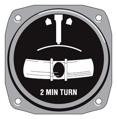
The turn and slip indicator is a gyroscopic flight instrument essential for , combining a rate-of-turn indicator and a slip-skid indicator to display the rate and direction of an 's turn as well as the quality of turn coordination by showing whether the is or skidding. It operates using a mounted in a vertical plane aligned with the 's longitudinal axis, where yawing motions cause gyroscopic that tilts the rotor and deflects a turn needle to indicate turn rate, with full needle deflection corresponding to a standard-rate turn of 3 degrees per second. The instrument's turn needle, often marked with a "doghouse" index for standard turns, provides pilots with immediate feedback on heading change direction and speed, while the —a liquid-filled, curved containing a ball—indicates coordination by remaining centered in a properly balanced turn, deflecting toward the inside of the turn in a slip (insufficient , turn rate too slow for ) or toward the outside in a skid (excessive , turn rate too fast for ). This dual functionality helps pilots maintain , reducing passenger discomfort and structural stress during maneuvers, and is particularly vital in (IFR) conditions where visual references are unavailable. Introduced as an early gyroscopic instrument in , the turn and slip indicator predates the more advanced turn coordinator and remains in use on older or simpler aircraft, powered by either vacuum systems that draw air through the gyro to spin it or electrically via a motor, with a failure flag indicating power loss. Unlike the turn coordinator, whose canted detects both roll and yaw for broader sensitivity to initial turn initiation, the turn and slip indicator focuses solely on yaw-induced turn rate and does not respond to , making it less versatile but reliable for steady-state turns without the risk of tumbling due to built-in restraining springs. In modern cockpits, it supports safe turn management by integrating with other instruments like the , ensuring pilots can execute precise maneuvers even in adverse weather.

Definition and History

Purpose and Function

The is a fundamental flight instrument in that integrates a gyroscopic needle for measuring turn rate with an ball for detecting lateral , enabling pilots to monitor and achieve coordinated turns. This combination provides essential feedback on the aircraft's yaw and roll coordination, helping to ensure stable and efficient maneuvering without excessive sideslip. The primary purpose of the turn and slip indicator is to assist pilots in avoiding uncoordinated flight conditions, such as slips or skids, which increase the risk of stalls, structural stress, or loss of control, especially during (IFR) operations in low-visibility environments. By promoting —where the aircraft's bank angle matches its rate of turn—the instrument enhances overall flight safety and serves as a reliable for attitude reference if primary systems like the fail. In operation, the needle deflects to the left or right to indicate the direction and approximate rate of yaw, typically calibrated for a standard-rate turn of 3 degrees per second, allowing a full 360-degree heading change in two minutes. The ball, housed in a curved , remains centered during but shifts toward the inside of a turn in a slip (indicating excess yaw relative to ) or toward the outside in a skid (indicating insufficient yaw), prompting corrections to recenter it. This instrument is essential for both (VFR) and IFR flights, and it is mandated for IFR operations in certified U.S. under FAA regulations (14 CFR § 91.205(d)).

Historical Development

The turn and slip indicator emerged in the early as aviation advanced beyond , with roots in World War I-era efforts to address pilot disorientation in poor visibility. Basic yaw detectors appeared on during the war, but the foundational gyroscopic turn indicator was invented in 1917 by Elmer A. Sperry, an American engineer known for his pioneering work in gyroscopic stabilization. This device used an air-driven to detect rate of turn, providing a needle deflection to indicate yaw without relying on external references, marking a shift from rudimentary compass-based navigation. By the and , as speeds and instrument flying demands increased, the turn indicator evolved into a combined instrument by integrating a simple —a curved with a ball in liquid—to show slip or skid during banked turns. A key milestone in parallel instrument development came in 1929 when Preston R. Bassett and Elmer A. Sperry Jr. filed a for a flight indicator that incorporated a gyroscopic artificial horizon with a banking indicator, providing pitch, roll, and slip/skid feedback to aid blind flying. This integration addressed the limitations of separate attitude and bank instruments, while the turn and slip indicator specifically combined the turn rate needle with the inclinometer for yaw and coordination monitoring. Post-World War II advancements standardized the instrument in through regulatory bodies like the Civil Aeronautics Administration (predecessor to the FAA, established in 1938). The turn coordinator variant, introduced in the , featured a canted tilted 30–45 degrees to sense both yaw and initial roll rates, improving responsiveness over traditional designs. By the , the turn and slip indicator (or its coordinator form) became mandatory for under evolving certification standards, driven by numerous accidents involving uncoordinated flight and in low visibility.

Design and Components

Turn Indicator

The turn indicator is a gyroscopic instrument designed to measure an aircraft's rate of turn by detecting about the yaw axis. At its core is a rate featuring a heavy rotor that spins at high speeds, approximately 8,000 RPM, to establish gyroscopic rigidity and enable precise sensing of yaw movements. The is oriented to rotate in a vertical plane aligned with the aircraft's longitudinal axis, allowing it to respond to changes in heading through the principle of . In terms of design, the instrument incorporates either an air-driven or electric , with the rotor's mechanically linked to a needle pointer on the instrument face. This pointer is calibrated in degrees per second, where a standard full-scale deflection indicates a turn rate of 3° per second, equivalent to completing a 360° turn in 2 minutes for standardized rate turns. Early models relied on pneumatic power supplied by engine-driven pumps to spin the rotor, providing a reliable but maintenance-intensive system common in mid-20th-century . Modern certified increasingly use electric , which offer greater dependability and eliminate the need for systems. The is mounted within a single suspension that permits freedom of movement specifically in the yaw axis while constraining other rotations, ensuring the isolates turn rate detection. Integrated springs provide to counteract any oscillations from forces, stabilizing the needle's response for accurate real-time indications. This turn indicator component is commonly paired with an in the full turn-and-slip instrument to provide comprehensive turn coordination data.

Inclinometer

The inclinometer, also known as the slip-skid ball, is a fundamental component of the turn and slip indicator that provides pilots with a visual cue for aircraft coordination during flight. It consists of a curved glass tube filled with damping fluid and containing a steel ball, typically black for visibility against a white background. The fluid serves to dampen the ball's movement, preventing erratic oscillations and ensuring stable readings. In operation, the ball responds solely to the resultant forces of and centrifugal acting on the . During straight-and-level flight or a perfectly coordinated turn, these forces balance such that the ball remains centered at the bottom of the tube. In uncoordinated flight, an imbalance occurs: if the slips toward the inside of the turn (insufficient ), the ball deflects to the left; if it skids outward (excessive ), the ball moves to the right. This deflection signals the pilot to apply corrective input—commonly remembered as "step on the ball"—to restore coordination. The design of the dates to the early days of , with the first production model featuring the steel ball in a introduced by the Sperry Company in 1918. Its low-technology construction, relying entirely on mechanical and gravitational principles, makes it highly reliable and independent of the aircraft's electrical or vacuum power systems, ensuring functionality even in the event of system failures. The curvature of the tube is calibrated to align with the dynamics of standard-rate turns, allowing the ball to accurately reflect coordination across typical flight conditions without requiring power assistance. When paired with the turn needle, the provides a complete picture of turn quality and yaw balance.

Turn Coordinator Variant

The turn coordinator represents an advanced variant of the turn and slip indicator, designed to provide pilots with more immediate feedback on turning motions by incorporating sensitivity to both yaw and roll rates. Unlike the traditional turn and slip indicator, which relies on a aligned horizontally to detect only yaw-induced turn rates, the turn coordinator features a mounted on a canted , typically tilted approximately 30 degrees upward from the 's longitudinal axis. This tilt allows the instrument to initially sense roll rate during the onset of a turn, offering an earlier indication of turn initiation before the fully establishes a coordinated yaw. Developed in the 1960s and introduced in the early 1970s, the turn coordinator evolved as an improvement over earlier yaw-only designs to enhance pilot awareness in dynamic flight conditions. Its display innovates by replacing the simple needle of the basic model with a symbolic miniature airplane or wing representation that banks in the direction of the roll, providing a more intuitive visual cue for turn rate and coordination. The instrument marks a standard-rate turn (3 degrees per second) on its scale, aiding precise maneuvering. This variant proves particularly responsive in steep turns or turbulent conditions, where the basic turn and slip indicator's yaw-only sensitivity may lag behind rapid attitude changes. By the 1970s, the turn coordinator had become a standard instrument in many general aviation aircraft, especially training models, due to its dual-rate detection and improved utility for instrument flight.

Principles of Operation

Turn Rate Measurement

The turn rate measurement in a turn and slip indicator operates on the principle of gyroscopic precession, where an applied torque from the aircraft's yaw rotation causes the gyroscope rotor to tilt perpendicular to the input axis. The gyroscope maintains rigidity in space through its high spin rate, typically around 10,000 RPM, generating significant angular momentum that resists changes in orientation. When the aircraft yaws, this torque induces precession—a secondary rotation 90 degrees displaced from the applied force in the direction of the rotor's spin—resulting in a tilt of the gyro assembly. Springs attached to the gimbal restrain this tilt, producing a steady-state deflection of the turn needle that is proportional to the yaw rate, allowing the instrument to quantify angular velocity in yaw. In a rate gyroscope, such as that used in the turn indicator, the precession angle θ balances the input against the spring , yielding a turn rate ω approximately equal to θ / τ, where τ represents the instrument's , influenced by the gyro's and the spring constant. The instrument face features markings for standard turn rates corresponding to completing 360° in ½, 1, 2, or , with full needle deflection calibrated to a standard rate of 3° per second, equivalent to a 2-minute turn used in instrument flight procedures. This design distinguishes rate gyroscopes from attitude gyroscopes; the former detect and display the rate of angular change via deflection without integrating to absolute position, providing quick response to yaw inputs but requiring periodic realignment for prolonged accuracy, while the latter maintain a fixed reference frame for pitch and roll orientation. Limitations arise from the single- configuration, which can introduce errors in high-rate turns due to gimbal constraints and spring limits, though restraining springs prevent tumbling.

Slip and Skid Indication

The slip and skid indication in a turn and slip indicator is provided by the , a simple device consisting of a curved partially filled with a such as , containing a small metal ball that moves freely under the influence of unbalanced lateral forces. This component detects deviations from by responding to the net lateral experienced by the during a turn, where the ball's position relative to the tube's centerline indicates whether the aircraft is slipping inward or skidding outward. In a banked turn, the physics governing the ball's deflection arises from the balance—or imbalance—between the acting outward on the and the horizontal component of the lift vector acting inward toward the turn's center. The , generated by the 's circular path, pushes the away from the turn's center, while the horizontal lift component, resulting from the angle, provides the necessary to maintain the turn. If the input does not properly coordinate with the angle, these forces become unbalanced, causing the ball to deflect from center: for instance, insufficient into the turn results in excess horizontal lift pulling the inward, while excessive creates an overabundance of pushing it outward. A slip occurs when the aircraft is overbanked relative to the turn rate, meaning the horizontal lift component exceeds the centrifugal force; in this case, the ball deflects toward the inside (low wing) of the turn, indicating the need for additional rudder into the turn to increase the turn rate or reduce the bank angle to center the ball. Conversely, a skid happens when the aircraft is underbanked for the turn rate, with centrifugal force overpowering the horizontal lift; here, the ball moves to the outside (high wing) of the turn, signaling the need for rudder opposite to the turn to decrease the turn rate or increase the bank angle to center the ball. The ball's position is proportional to the net lateral , which can be expressed as: anet=V2Rcosϕgsinϕa_{\text{net}} = \frac{V^2}{R} \cos \phi - g \sin \phi where VV is the , RR is the turn radius, gg is the acceleration due to gravity, and ϕ\phi is the bank angle; a positive value indicates a skid (outward deflection), a negative value a slip (inward deflection), and zero corresponds to . Maintaining zero ball deflection is critical for coordinated flight, as uncoordinated slips or skids can induce adverse yaw, increase the risk of a stall on the inside wing due to higher angle of attack, or lead to loss of control, particularly at low speeds or high angles of attack.

Usage and Interpretation

In Flight Maneuvers

Pilots utilize the turn and slip indicator to maintain coordinated flight during standard rate turns, which are defined as a constant turn rate of 3 degrees per second, allowing a complete 360-degree heading change in two minutes. To achieve this, the needle is aligned with the standard rate marking on the instrument, while the inclinometer ball is kept centered through rudder inputs or trim adjustments, ensuring no slip or skid occurs. In steep turns exceeding 45 degrees of , pilots must apply increased pressure to counteract and effects, keeping the ball centered for coordination and preventing overbanking or skidding tendencies. During stalls, particularly accelerated stalls in steep turns, continuous monitoring of the instrument is essential to detect and correct any slip, as an uncoordinated condition can lead to a spin entry; is used to neutralize the ball's deflection promptly. In (IMC), the turn and slip indicator serves as a backup for attitude awareness, cross-checked frequently with the to confirm turn rate and direction while establishing a wings-level attitude. However, the instrument exhibits limitations in , where the needle may lag behind actual motion due to gyroscopic and rough air disturbances, potentially leading to erratic or delayed indications. A key technique for correction is the "step on the ball" rule, where pilots apply pedal pressure toward the direction of the 's deflection to recenter it, effectively steering into a slip or away from a skid during any maneuver. This method promotes efficient, and enhances safety by minimizing lateral acceleration forces on the aircraft.

Training Applications

The turn and slip indicator plays a central role in primary pilot training by teaching , where students learn to use ailerons and inputs to keep the ball centered, preventing slips and skids during turns. Instructors often demonstrate —a coupled lateral-directional —by applying inputs to induce yaw, allowing trainees to observe the ball's deflection and practice corrective actions to restore coordination, thereby illustrating the effects of uncoordinated flight on stability. This hands-on approach builds foundational skills in maintaining balanced forces, as uncoordinated maneuvers can lead to increased drag and potential stalls. In instrument training, the turn and slip indicator supports partial panel scenarios, where the is covered or failed, forcing pilots to rely on it as a backup for monitoring bank angle and turn quality to maintain . During hood flying—simulated instrument conditions with a view-limiting device—it aids in building scan discipline by requiring cross-checks with other instruments to ensure coordinated turns while referencing solely to the panel. According to the FAA Private Pilot Airplane Airman Certification Standards (ACS), applicants must demonstrate proficiency in interpreting the during VFR basic instrument maneuvers, such as turns to headings, to maintain within specified tolerances like heading ±10° and coordinated . For (IFR) training, the standards extend this to timed standard-rate turns at 3° per second, using the indicator to achieve and hold the rate while keeping the ball centered. The instrument is commonly featured in simulator sessions for upset recovery training, where pilots practice recognizing and correcting sideslip by centering the ball, serving as a yaw coordinator to enhance control effectiveness during high-stress recoveries from unusual attitudes.

Regulatory and Practical Considerations

In the United States, the (FAA) mandates a slip-skid indicator as part of the required for (IFR) operations in powered civil aircraft with standard airworthiness certificates, per 14 CFR § 91.205(d)(4). This requirement ensures pilots can maintain during instrument conditions, and it applies regardless of altitude. Additionally, a gyroscopic rate-of-turn indicator is required under § 91.205(d)(3), unless the aircraft is equipped with a third approved for use through 360 degrees of pitch and roll, in which case the rate-of-turn function may be omitted. A turn coordinator, which integrates both rate-of-turn and slip-skid indications, serves as an FAA-approved equivalent for these functions. For (VFR) operations under 14 CFR Part 91, no turn and slip indicator or equivalent is required for day or night flights in powered civil . However, under Part 135 for commuter and on-demand operations, both a gyroscopic rate-of-turn indicator and a slip-skid indicator are mandatory when carrying passengers on VFR over-the-top flights, unless the has specific attitude instrumentation exemptions (with additional exceptions for certain helicopters). Ultralight vehicles operating under Part 103 and most under Part 91 for VFR are exempt from these instrument requirements, as they fall outside standard certification categories for powered civil . Internationally, the (ICAO) Annex 6, Part I, requires a turn and slip indicator for aeroplanes engaged in international commercial air transport operations under IFR, as part of the basic to monitor turn rate and coordination. Similar provisions apply in Annex 6, Part II, for aeroplanes, with allowances for combined instruments meeting the turn, slip, attitude, and heading requirements. Exceptions mirror FAA categories, excluding ultralights and from these mandates for non-commercial, non-IFR flights. Post-2000 FAA updates have permitted electronic equivalents to traditional mechanical turn and slip indicators, provided they comply with Order (TSO) C3e for turn and slip functions or relevant TSOs for integrated systems like electronic flight instrument systems (EFIS). These approvals, facilitated by advisory circulars and policy statements, allow TSO-certified digital displays to substitute for gyroscopic instruments in certified , enhancing reliability while maintaining for both VFR and IFR operations.

Installation and Limitations

The installation of a turn and slip indicator requires careful placement within the instrument panel to ensure accessibility and minimal interference with other , typically positioning the unit in the lower portion of the panel for pilot visibility during coordinated turns. Vacuum-driven models rely on a pneumatic providing 2 inches of mercury specifically for the gyroscopic turn , while electric variants connect to the 's 14- or 28-volt DC bus with appropriate circuit protection. Alignment is critical, with the gyro rotor mounted to rotate in the vertical plane parallel to the 's longitudinal axis, necessitating leveling of the during installation to calibrate the ball for accurate slip-skid indication under straight-and-level flight conditions. Calibration follows guidelines in FAA 43.13-1B, including functional checks of gyro spin-up time (typically 3-5 minutes) and verification of standard-rate turn markings (3° per second) against known , often performed by certified technicians. Operational limitations of the turn and slip indicator stem primarily from its gyroscopic design, which experiences gradual drift due to internal friction and over extended use without realignment, rendering it unsuitable for precise tasks beyond basic rate-of-turn monitoring. Failure modes include gyro tumble or erratic indications from loss (below 4.5 inches Hg suction), often signaled by a low-pressure warning light, or electrical faults in powered units leading to total instrument failure; the single-gimbal restraint prevents full tumbling but not inaccuracy under extreme maneuvers. Maintenance is mandated every 100 hours of operation for used in commercial service, encompassing visual inspections for fluid leaks in the , gyro bearing smoothness, and suction/electrical continuity, with more frequent preflight checks recommended to detect anomalies early. Common issues differ between certified and : certified models adhere to strict Data Sheet schedules, while experimental ones rely on annual condition inspections under 14 CFR Part 91.411, potentially allowing deferred maintenance if airworthiness is demonstrated. In modern glass cockpits equipped with electronic flight instrument systems, the turn and slip indicator serves as a reliable , providing independent mechanical or vacuum/electric against primary display failures, often retained in the panel alongside attitude and heading reference systems for enhanced safety. Environmental constraints limit operation to temperatures between -20°C and +50°C, beyond which gyro sensitivity and fluid may degrade, as specified in orders like TSO-C3e for turn indicators.

References

Add your contribution
Related Hubs
User Avatar
No comments yet.