Directional antenna
View on Wikipedia


A directional antenna or beam antenna is an antenna that radiates or receives greater radio wave power in specific directions. Directional antennas can radiate radio waves in beams, when greater concentration of radiation in a certain direction is desired, or in receiving antennas receive radio waves from one specific direction only. This can increase the power transmitted to receivers in that direction, or reduce interference from unwanted sources. This contrasts with omnidirectional antennas such as dipole antennas which radiate radio waves over a wide angle, or receive from a wide angle.
The extent to which an antenna's angular distribution of radiated power, its radiation pattern, is concentrated in one direction is measured by a parameter called antenna gain. A high-gain antenna (HGA) is a directional antenna with a focused, narrow beam width, permitting more precise targeting of the radio signals.[1] Most commonly referred to during space missions,[2] these antennas are also in use all over Earth, most successfully in flat, open areas where there are no mountains to disrupt radiowaves.[citation needed]
In contrast, a low-gain antenna (LGA) is an omnidirectional antenna, with a broad radiowave beam width, that allows the signal to propagate reasonably well even in mountainous regions and is thus more reliable regardless of terrain. Low-gain antennas are often used in spacecraft as a backup to the high-gain antenna, which transmits a much narrower beam and is therefore susceptible to loss of signal.[3]
All practical antennas are at least somewhat directional, although usually only the direction in the plane parallel to the earth is considered, and practical antennas can easily be omnidirectional in one plane. The most common directional antenna types are[citation needed]
- the Yagi–Uda antenna,
- the log-periodic antenna, and
- the corner reflector antenna.
- the Hexbeam
These antenna types, or combinations of several single-frequency versions of one type or (rarely) a combination of two different types, are frequently sold commercially as residential TV antennas. Cellular repeaters often make use of external directional antennas to give a far greater signal than can be obtained on a standard cell phone. Satellite television receivers usually use parabolic antennas. For long and medium wavelength frequencies, tower arrays are used in most cases as directional antennas.
Principle of operation
[edit]When transmitting, a high-gain antenna allows more of the transmitted power to be sent in the direction of the receiver, increasing the received signal strength. When receiving, a high gain antenna captures more of the signal, again increasing signal strength. Due to reciprocity, these two effects are equal—an antenna that makes a transmitted signal 100 times stronger (compared to an isotropic radiator) will also capture 100 times as much energy as the isotropic antenna when used as a receiving antenna. As a consequence of their directivity, directional antennas also send less (and receive less) signal from directions other than the main beam. This property may avoid interference from other out-of-beam transmitters, and always reduces antenna noise. (Noise comes from every direction, but a desired signal will only come from one approximate direction, so the narrower the antenna's beam, the better the crucial signal-to-noise ratio.)
There are many ways to make a high-gain antenna; the most common are parabolic antennas, helical antennas, Yagi-Uda antennas, and phased arrays of smaller antennas of any kind. Horn antennas can also be constructed with high gain, but are less commonly seen. Still other configurations are possible—the Arecibo Observatory used a combination of a line feed with an enormous spherical reflector (as opposed to a more usual parabolic reflector), to achieve extremely high gains at specific frequencies.
Antenna gain
[edit]Antenna gain is often quoted with respect to a hypothetical antenna that radiates equally in all directions, an isotropic radiator. This gain, when measured in decibels, is called dBi. Conservation of energy dictates that high gain antennas must have narrow beams.[citation needed] For example, if a high gain antenna makes a 1 Watt transmitter look like a 100 Watt transmitter, then the beam can cover at most 1/100 of the sky (otherwise the total amount of energy radiated in all directions would sum to more than the transmitter power, which is not possible). In turn this implies that high-gain antennas must be physically large, since according to the diffraction limit, the narrower the beam desired, the larger the antenna must be (measured in wavelengths).
Antenna gain can also be measured in dBd, which is gain in decibels compared to the maximum intensity direction of a half wave dipole. In the case of Yagi-type aerials this more or less equates to the gain one would expect from the aerial under test minus all its directors and reflector. It is important not to confuse dBi and dBd; the two differ by 2.15 dB, with the dBi figure being higher, since a dipole has 2.15 dB of gain with respect to an isotropic antenna.
Gain is also dependent on the number of elements and the tuning of those elements. Antennas can be tuned to be resonant over a wider spread of frequencies but, all other things being equal, this will mean the gain of the aerial is lower than one tuned for a single frequency or a group of frequencies. For example, in the case of wideband TV antennas the fall off in gain is particularly large at the bottom of the TV transmitting band. In the UK this bottom third of the TV band is known as group A.[citation needed]
Other factors which may also affect gain include aperture (the area the antenna collects signal from, almost entirely related to the size of the antenna but for small antennas can be increased by adding a ferrite rod), and efficiency (again, affected by size, but also resistivity of the materials used and impedance matching). These factors are easy to improve without adjusting other features of the antennas or coincidentally improved by the same factors that increase directivity, and so are typically not emphasized.
Applications
[edit]High gain antennas are typically the largest component of deep space probes, and the highest gain radio antennas are physically enormous structures, such as the Arecibo Observatory. The Deep Space Network uses 35 m dishes at about 1 cm wavelengths. This combination gives the antenna gain of about 100,000,000 (or 80 dB, as normally measured), making the transmitter appear about 100 million times stronger, and a receiver about 100 million times more sensitive, provided the target is within the beam. This beam can cover at most one hundred millionth (10−8) of the sky, so very accurate pointing is required.
Use of high gain and millimeter-wave communication in WPAN gaining increases the probability of concurrent scheduling of non‐interfering transmissions in a localized area, which results in an immense increase in network throughput. However, the optimum scheduling of concurrent transmission is an NP-hard problem.[4]
Gallery
[edit]-
 An early example (1922) of a directional AM radio transmitter using a long wire antenna, built for WOR, then in Newark, New Jersey and targeting both New York City and Philadelphia in addition to Newark.
 -
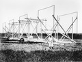 Karl Jansky and his rotating directional radio antenna (1932) in Holmdel, New Jersey, which was the world's first radio telescope, discovering radio emissions from the Milky Way.
 -
 Grote Reber's homemade antenna in Wheaton, Illinois (1937), world's second radio telescope and first parabolic radio telescope
 -
![Holmdel Horn Antenna in Holmdel, New Jersey (1960s). Built to support the Echo satellite communication program,[5] it was later used in experiments that revealed the Cosmic microwave background permeating the universe.[6]](//upload.wikimedia.org/wikipedia/commons/thumb/f/f7/Horn_Antenna-in_Holmdel%2C_New_Jersey_-_restoration1.jpg/120px-Horn_Antenna-in_Holmdel%2C_New_Jersey_-_restoration1.jpg) Holmdel Horn Antenna in Holmdel, New Jersey (1960s). Built to support the Echo satellite communication program,[5] it was later used in experiments that revealed the Cosmic microwave background permeating the universe.[6]
Holmdel Horn Antenna in Holmdel, New Jersey (1960s). Built to support the Echo satellite communication program,[5] it was later used in experiments that revealed the Cosmic microwave background permeating the universe.[6] -
 Parabolic antenna – the 70 m antenna at Goldstone Deep Space Communications Complex in the Mojave Desert, California
 -
 Voyager 2 spacecraft. The HGA (a parabolic antenna) is the large bowl-shaped object.
 -
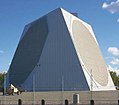 A giant phased-array radar in Alaska
 -
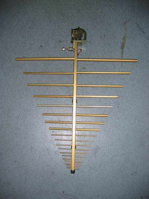
 A Yagi-Uda antenna. From left to right, the elements mounted on the boom are called the reflector, driven element, and director. The reflector is easily identified as being a bit longer (5% or more) than all the other elements, and the director(s) a bit shorter (5% or more).


![Holmdel Horn Antenna in Holmdel, New Jersey (1960s). Built to support the Echo satellite communication program,[5] it was later used in experiments that revealed the Cosmic microwave background permeating the universe.[6]](https://en.wikipedia.org/wiki/File:Horn_Antenna-in_Holmdel,_New_Jersey_-_restoration1.jpg)


See also
[edit]References
[edit]- ^ Zainah Md Zain; Hamzah Ahmad; Dwi Pebrianti; Mahfuzah Mustafa; Nor Rul Hasma Abdullah; Rosdiyana Samad; Maziyah Mat Noh (2020). Proceedings of the 11th National Technical Seminar on Unmanned System Technology 2019: NUSYS'19. Springer Nature. p. 535. ISBN 978-981-15-5281-6. Extract of page 535
- ^ Joseph A. Angelo (2014). Encyclopedia of Space and Astronomy. Infobase Publishing. p. 364. ISBN 978-1-4381-1018-9. Extract of page 364
- ^ "Low-gain antenna". Oxford Reference (oxfordreference.com).
- ^ Bilal, Muhammad; et al. (2014). "Time-slotted scheduling schemes for multi-hop concurrent transmission in WPANs with directional antennas". ETRI Journal. 36 (3): 374–384. arXiv:1801.06018. doi:10.4218/etrij.14.0113.0703. S2CID 2285688.
- ^ Crawford, A.B.; Hogg, D.C.; Hunt, L.E. (July 1961). "Project Echo: A horn-reflector antenna for space communication". The Bell System Technical Journal: 1095–1099. doi:10.1002/j.1538-7305.1961.tb01639.x.
- ^ "Horn antenna". Astronomy and astrophysics. History. U.S. National Park Service. 2001-11-05. Archived from the original on 2008-05-12. Retrieved 2008-05-23.
External links
[edit]- "What are high and low gain?". qrg.northwestern.edu. Communications. Evanston, IL: Northwestern University.