Hubbry Logo
Radiation patternRadiation patternMain
Open search
Radiation pattern
Community hub
Radiation pattern
logo
8 pages, 0 posts
0 subscribers
Be the first to start a discussion here.
Contribute something
Radiation pattern
Radiation pattern
from Wikipedia
Three-dimensional antenna radiation patterns. The radial distance from the origin in any direction represents the strength of radiation emitted in that direction. The top shows the directive pattern of a horn antenna, the bottom shows the omnidirectional pattern of a simple vertical dipole antenna.

An antenna radiation pattern (or antenna pattern or far-field pattern) is the directional (angular) dependence of the field strength (sometimes also the phase) of the radio waves from the antenna or other source.[1][2][3]

Particularly in the fields of fiber optics, lasers, and integrated optics, the term radiation pattern may also be used as a synonym for the near-field pattern or Fresnel pattern.[4] This refers to the positional dependence of the electromagnetic field in the near field, or Fresnel region of the source. The near-field pattern is most commonly defined over a plane placed in front of the source, or over a cylindrical or spherical surface enclosing it.[1][4]

The far-field pattern of an antenna may be determined experimentally at an antenna range, or alternatively, the near-field pattern may be found using a near-field scanner, and the radiation pattern deduced from it by computation.[1] The far-field radiation pattern can also be calculated from the antenna shape by computer programs such as NEC. Other software, like HFSS can also compute the near field.

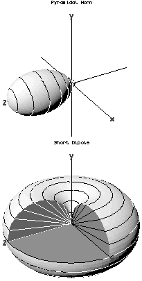
The far field radiation pattern may be represented graphically as a plot of one of a number of related variables, like the strength at a constant (large) radius (an amplitude pattern or field pattern), the power per unit solid angle (power pattern), and the directive gain (gain pattern). Very often, only the relative amplitude is plotted, normalized either to the amplitude on the antenna boresight, or to the total radiated power. The plotted quantity may be shown on a linear scale, or in dB. The plot is typically represented as a three-dimensional graph (as at right), or as separate graphs in the vertical plane and horizontal plane. This is often known as a polar diagram.

Reciprocity

[edit]
The radiation patterns of a vertical half-wave dipole, an omnidirectional antenna. The horizontal and vertical polar patterns are projections of the 3 dimensional pattern onto horizontal and vertical planes, respectively. An omnidirectional antenna radiates equal signal strength in all horizontal directions, so its horizontal pattern is just a circle.

It is a fundamental property of antennas that the receiving pattern (sensitivity as a function of direction) of an antenna when used for receiving is identical to the far-field radiation pattern of the antenna when used for transmitting. This is a consequence of the reciprocity theorem of electromagnetics and is proved below. Therefore, in discussions of radiation patterns the antenna can be viewed as either transmitting or receiving, whichever is more convenient.

There are limits to reciprocity: It applies only to passive antenna elements – active antennas that incorporate amplifiers or other individually powered components are not reciprocal. And even when the antenna is made of exclusively of passive elements, reciprocity only applies to the waves emitted and intercepted by the antenna. Reciprocity does not apply to the distribution of current in the various parts of the antenna generated by the intercepted waves nor currents that create emitted waves: Antenna current profiles typically differ for receiving and transmitting, despite the waves in the far field radiating inward and outward along the same path, with the same overall pattern, just with reversed direction.

Typical patterns

[edit]
Typical polar radiation plot. Most antennas show a pattern of "lobes" or maxima of radiation. In a directive antenna, shown here, the largest lobe, in the desired direction of propagation, is called the "main lobe". The other lobes are called "sidelobes" and usually represent radiation in unwanted directions.

Since electromagnetic radiation is dipole radiation, it is not possible to build an antenna that radiates coherently equally in all directions, although such a hypothetical isotropic antenna is used as a reference to calculate antenna gain.

The simplest antennas, monopole and dipole antennas, consist of one or two straight metal rods along a common axis. These axially symmetric antennas have radiation patterns with a similar symmetry, called omnidirectional patterns; they radiate equal power in all directions perpendicular to the antenna, with the power varying only with the angle to the axis, dropping off to zero on the antenna's axis. This illustrates the general principle that if the shape of an antenna is symmetrical, its radiation pattern will have the same symmetry.

In most antennas, the radiation from the different parts of the antenna interferes at some angles; the radiation pattern of the antenna can be considered an interference pattern. This results in minimum or zero radiation at certain angles where the radio waves from the different parts arrive out of phase, and local maxima of radiation at other angles where the radio waves arrive in phase. Therefore, the radiation plot of most antennas shows a pattern of maxima called "lobes" at various angles, separated by "nulls" at which the radiation goes to zero. The larger the antenna is compared to a wavelength, the more lobes there will be.

A rectangular radiation plot, an alternative presentation method to a polar plot

In a directional antenna in which the objective is to emit the radio waves in one particular direction, the antenna is designed to radiate most of its power in the lobe directed in the desired direction. Therefore, in the radiation plot this lobe appears larger than the others; it is called the "main lobe". The axis of maximum radiation, passing through the center of the main lobe, is called the "beam axis" or boresight axis". In some antennas, such as split-beam antennas, there may exist more than one major lobe. The other lobes beside the main lobe, representing unwanted radiation in other directions, are called minor lobes. The minor lobes oriented at an angle to the main lobe are called "side lobes". The minor lobe in the opposite direction (180°) from the main lobe is called the "back lobe".

Minor lobes usually represent radiation in undesired directions, so in directional antennas a design goal is usually to reduce the minor lobes. Side lobes are normally the largest of the minor lobes. The level of minor lobes is usually expressed as a ratio of the power density in the lobe in question to that of the major lobe. This ratio is often termed the side lobe ratio or side lobe level. Side lobe levels of −20 dB or greater are usually not desirable in many applications. Attainment of a side lobe level smaller than −30 dB usually requires very careful design and construction. In most radar systems, for example, low side lobe ratios are very important to minimize false target indications through the side lobes.

Proof of reciprocity

[edit]

For a complete proof, see the reciprocity (electromagnetism) article. Here, we present a common simple proof limited to the approximation of two antennas separated by a large distance compared to the size of the antenna, in a homogeneous medium. The first antenna is the test antenna whose patterns are to be investigated; this antenna is free to point in any direction. The second antenna is a reference antenna, which points rigidly at the first antenna.

Each antenna is alternately connected to a transmitter having a particular source impedance, and a receiver having the same input impedance (the impedance may differ between the two antennas).

It is assumed that the two antennas are sufficiently far apart that the properties of the transmitting antenna are not affected by the load placed upon it by the receiving antenna. Consequently, the amount of power transferred from the transmitter to the receiver can be expressed as the product of two independent factors; one depending on the directional properties of the transmitting antenna, and the other depending on the directional properties of the receiving antenna.

For the transmitting antenna, by the definition of gain, , the radiation power density at a distance from the antenna (i.e. the power passing through unit area) is

.

Here, the angles and indicate a dependence on direction from the antenna, and stands for the power the transmitter would deliver into a matched load. The gain may be broken down into three factors; the antenna gain (the directional redistribution of the power), the radiation efficiency (accounting for ohmic losses in the antenna), and lastly the loss due to mismatch between the antenna and transmitter. Strictly, to include the mismatch, it should be called the realized gain,[4] but this is not common usage.

For the receiving antenna, the power delivered to the receiver is

.

Here is the power density of the incident radiation, and is the antenna aperture or effective area of the antenna (the area the antenna would need to occupy in order to intercept the observed captured power). The directional arguments are now relative to the receiving antenna, and again is taken to include ohmic and mismatch losses.

Putting these expressions together, the power transferred from transmitter to receiver is

,

where and are directionally dependent properties of the transmitting and receiving antennas respectively. For transmission from the reference antenna (2), to the test antenna (1), that is

,

and for transmission in the opposite direction

.

Here, the gain and effective area of antenna 2 are fixed, because the orientation of this antenna is fixed with respect to the first.

Now for a given disposition of the antennas, the reciprocity theorem requires that the power transfer is equally effective in each direction, i.e.

,

whence

.

But the right hand side of this equation is fixed (because the orientation of antenna 2 is fixed), and so

,

i.e. the directional dependence of the (receiving) effective aperture and the (transmitting) gain are identical (QED). Furthermore, the constant of proportionality is the same irrespective of the nature of the antenna, and so must be the same for all antennas. Analysis of a particular antenna (such as a Hertzian dipole), shows that this constant is , where is the free-space wavelength. Hence, for any antenna the gain and the effective aperture are related by

.

Even for a receiving antenna, it is more usual to state the gain than to specify the effective aperture. The power delivered to the receiver is therefore more usually written as

(see link budget). The effective aperture is however of interest for comparison with the actual physical size of the antenna.

Practical consequences

[edit]
  • When determining the pattern of a receiving antenna by computer simulation, it is not necessary to perform a calculation for every possible angle of incidence. Instead, the radiation pattern of the antenna is determined by a single simulation, and the receiving pattern inferred by reciprocity.
  • When determining the pattern of an antenna by measurement, the antenna may be either receiving or transmitting, whichever is more convenient.
  • For a practical antenna, the side lobe level should be minimum, it is necessary to have the maximum directivity.[5]

See also

[edit]

References

[edit]
[edit]
Revisions and contributorsEdit on WikipediaRead on Wikipedia
from Grokipedia
A radiation pattern is a graphical representation of the radiation properties of an antenna as a function of angular coordinates, depicting the relative distribution of radiated power or in various directions. This pattern arises from the antenna's interaction with electromagnetic waves, illustrating how energy is emitted or received spatially. It serves as a fundamental tool in antenna and , enabling engineers to evaluate performance metrics such as coverage and interference. Radiation patterns typically consist of several components, including the main lobe, which represents the primary direction of maximum radiation; side lobes, indicating secondary radiation that can cause inefficiencies; and back lobes, showing radiation in the opposite direction from the main lobe. These elements are plotted in polar coordinates for two-dimensional views (e.g., E-plane or H-plane) or three-dimensional spherical formats, often normalized to 0 dB at the peak and scaled linearly or logarithmically. Nulls, or regions of minimal radiation between lobes, further define the pattern's selectivity. Key parameters extracted from the radiation pattern include the half-power beamwidth, the angular width of the at -3 dB from its peak, which quantifies the antenna's . measures the concentration of radiation in a particular direction relative to an , while gain accounts for losses and is expressed as gain(θ, φ) = η D(θ, φ), where η is . Patterns can be omnidirectional, radiating uniformly in a plane (e.g., doughnut-shaped for a ), or directional, focusing energy for applications like or broadcasting. In practice, radiation patterns are measured in far-field conditions to ensure accurate representation of free-space behavior, influencing applications from communications to systems. Variations in pattern shape, such as pencil-beam or fan-beam, are tailored to specific needs, with side lobe suppression being a goal to minimize unwanted emissions.

Fundamentals

Definition and Basic Concepts

A radiation pattern describes the angular distribution of radiated or received power from an antenna or radiating structure as a function of direction in space. It characterizes how the strength varies with spherical coordinates θ and φ, typically representing the magnitude of the electric or in the far zone. The concept of radiation patterns has roots in the late 19th-century experiments of , who in 1887 demonstrated the directional nature of electromagnetic waves using dipole antennas. Further advancements occurred in early 20th-century antenna work, including Karl Jansky's employment of directional antennas in the early 1930s to detect cosmic radio waves, advancing the understanding of angular power distribution in . Radiation patterns are valid in the far-field region, where the distance rr from the antenna satisfies rλ2πr \gg \frac{\lambda}{2\pi} (with λ as the wavelength) for the theoretical approximation ensuring the field behaves as a locally , and the power density is proportional to E(θ,ϕ)2|\mathbf{E}(\theta, \phi)|^2 or H(θ,ϕ)2|\mathbf{H}(\theta, \phi)|^2. For practical finite-sized antennas, the distance should also satisfy r>2D2λr > \frac{2D^2}{\lambda}, where D is the maximum linear dimension of the antenna, to minimize phase errors and accurately represent the pattern. This approximation ignores the reactive near-fields close to the antenna, which involve non-propagating energy storage and radial field components that do not contribute to distant power transfer. An ideal reference for radiation patterns is the , which hypothetically emits uniform power in all directions, producing a spherical pattern with constant intensity over the unit sphere. Real antennas approximate this in certain directions but exhibit variations due to their geometry and excitation. By the reciprocity principle, the radiation pattern remains identical for transmission and reception under the same conditions.

Mathematical Description

The radiation pattern of an antenna in the far field is mathematically described by the radiation intensity U(θ,ϕ)U(\theta, \phi), which represents the power radiated per unit solid angle in the direction defined by the spherical coordinates θ\theta (polar angle from the reference axis) and ϕ\phi (azimuthal angle). This quantity is given by U(θ,ϕ)=r2SavgU(\theta, \phi) = r^2 | \mathbf{S}_\text{avg} |, where rr is the radial distance from the antenna and Savg\mathbf{S}_\text{avg} is the magnitude of the time-averaged Poynting vector pointing radially outward. In the far-field region, where the radial components of the fields are negligible and the electric and magnetic fields are related by the free-space impedance η377Ω\eta \approx 377 \, \Omega, the time-averaged Poynting vector simplifies to Savg=12ηE(θ,ϕ)2| \mathbf{S}_\text{avg} | = \frac{1}{2\eta} | \mathbf{E}(\theta, \phi) |^2, with E(θ,ϕ)\mathbf{E}(\theta, \phi) being the transverse electric field. Thus, the radiation intensity takes the form U(θ,ϕ)=r22ηE(θ,ϕ)2U(\theta, \phi) = \frac{r^2}{2\eta} | \mathbf{E}(\theta, \phi) |^2, independent of rr in the far field. The normalized radiation pattern F(θ,ϕ)F(\theta, \phi), which highlights the directional dependence, is defined as F(θ,ϕ)=U(θ,ϕ)UmaxF(\theta, \phi) = \frac{U(\theta, \phi)}{U_\text{max}}, where UmaxU_\text{max} is the maximum value of U(θ,ϕ)U(\theta, \phi). This normalization yields a dimensionless function ranging from 0 to 1, often expressed in decibels as 10log10F(θ,ϕ)10 \log_{10} F(\theta, \phi) for logarithmic plotting to emphasize variations in directivity. For antennas with linear polarization, such as those producing a field primarily in the or direction, F(θ,ϕ)F(\theta, \phi) directly relates to the squared magnitude of the normalized electric field components in spherical coordinates. The far-field E(θ,ϕ)\mathbf{E}(\theta, \phi), and thus the radiation pattern, derives from the current distribution J(r)\mathbf{J}(\mathbf{r}') on or within the antenna through the A\mathbf{A}. In the far-field approximation (rλr \gg \lambda, where λ\lambda is the ), the vector potential is A(r)=μ4πVJ(r)ejkrrrrdV\mathbf{A}(\mathbf{r}) = \frac{\mu}{4\pi} \int_V \mathbf{J}(\mathbf{r}') \frac{e^{-j k |\mathbf{r} - \mathbf{r}'|}}{|\mathbf{r} - \mathbf{r}'|} dV', with μ\mu the permeability of free space and k=2π/λk = 2\pi / \lambda the . Approximating rrrr^r|\mathbf{r} - \mathbf{r}'| \approx r - \hat{r} \cdot \mathbf{r}' for large rr, this becomes A(θ,ϕ)μejkr4πrVJ(r)ejkrdV\mathbf{A}(\theta, \phi) \approx \frac{\mu e^{-j k r}}{4\pi r} \int_V \mathbf{J}(\mathbf{r}') e^{j \mathbf{k} \cdot \mathbf{r}'} dV', where k=kr^\mathbf{k} = k \hat{r}. The transverse far-field is then E(θ,ϕ)jω(θ^Aθ+ϕ^Aϕ)\mathbf{E}(\theta, \phi) \approx -j \omega \left( \hat{\theta} A_\theta + \hat{\phi} A_\phi \right), linking the pattern directly to the Fourier transform of the current distribution projected onto the transverse directions. For linearly polarized antennas, one component (e.g., EθE_\theta) often dominates, simplifying the expression to Eθ(θ,ϕ)jωejkr4πrVJθ(r)ejkrdVE_\theta(\theta, \phi) \approx -j \omega \frac{e^{-j k r}}{4\pi r} \int_V J_\theta(\mathbf{r}') e^{j \mathbf{k} \cdot \mathbf{r}'} dV'. The total radiated power PradP_\text{rad} connects the radiation intensity to the overall antenna performance via integration over the full : Prad=4πU(θ,ϕ)dΩ=02π0πU(θ,ϕ)sinθdθdϕ,P_\text{rad} = \int_{4\pi} U(\theta, \phi) \, d\Omega = \int_0^{2\pi} \int_0^\pi U(\theta, \phi) \sin \theta \, d\theta \, d\phi, where dΩ=sinθdθdϕd\Omega = \sin \theta \, d\theta \, d\phi is the differential element in spherical coordinates. This integral quantifies the antenna's in converting input power to radiated , with the sinθ\sin \theta factor arising from the of .

Visualization and Analysis

Plotting Methods

Radiation patterns are graphically represented to visualize the directional dependence of radiated power from an antenna, typically derived from the radiation intensity function U(θ, φ). Polar plots provide a two-dimensional representation in specific angular planes, such as the elevation plane (varying θ at fixed φ) or the azimuth plane (varying φ at fixed θ), where the radial distance from the origin is proportional to the field strength or power, often normalized to the maximum value. These plots are commonly scaled in decibels (dB) for logarithmic compression, which emphasizes the dynamic range and highlights features like sidelobes relative to the main beam. Cartesian plots serve as an alternative for analyzing pattern cuts, particularly in the principal E-plane ( polarization plane, constant φ) and H-plane ( plane, θ = 90°), where the intensity or gain is plotted against angular coordinates on linear or logarithmic scales. This format facilitates precise quantification of beam characteristics, such as half-power beamwidth, though it is less intuitive for directional interpretation compared to polar coordinates. For a comprehensive view, three-dimensional representations depict the full angular coverage over a surrounding the antenna, often as a surface plot where the radius corresponds to the normalized field or power, or as contour maps on the spherical surface to show variations in θ and φ. These 3D plots reveal the overall shape, such as the toroidal pattern of a half-wave , and are generated by interpolating data across all directions. Standard conventions define θ as the polar angle (elevation) from 0° to 180° (though often 0° to 90° for upper-hemisphere patterns) measured from the z-axis, and φ as the azimuthal angle from 0° to 360° in the xy-plane; sketches typically annotate radiation lobes, nulls, and the main beam direction for clarity. Modern electromagnetic simulation software, such as and CST Studio Suite, automates the generation of these polar, Cartesian, and 3D plots through finite element or time-domain solvers, enabling accurate visualization of complex patterns since their advancements in the early 2000s.

Key Parameters

The key parameters of a radiation pattern quantify its directional properties and performance metrics, derived from the radiation intensity U(θ,ϕ)U(\theta, \phi) and total radiated power PradP_{\text{rad}}. These include , half-power beamwidth, sidelobe level, front-to-back , and measures of such as cross-polarization . They provide numerical insights into how effectively an antenna concentrates energy in desired directions while minimizing unwanted radiation. Directivity D(θ,ϕ)D(\theta, \phi) measures the concentration of radiated power in a particular direction relative to an with the same total power. It is defined as D(θ,ϕ)=U(θ,ϕ)Prad/4π,D(\theta, \phi) = \frac{U(\theta, \phi)}{P_{\text{rad}} / 4\pi}, where U(θ,ϕ)U(\theta, \phi) is the radiation intensity in steradians. The maximum D0D_0 occurs at the direction of peak intensity and is given by D0=4πUmaxPrad,D_0 = \frac{4\pi U_{\max}}{P_{\text{rad}}}, often expressed in dimensionless units or decibels (dBi relative to isotropic). For example, an infinitesimal dipole has D0=1.5D_0 = 1.5. The half-power beamwidth (HPBW) characterizes the angular width of the main lobe, defined as the angle between the two directions in that lobe where the radiation intensity drops to half its maximum value (U=0.5UmaxU = 0.5 U_{\max}). Expressed in degrees, HPBW indicates the antenna's resolution or beam sharpness; narrower values correspond to higher but require larger apertures. It is typically measured from polar plots of the pattern. Sidelobe level quantifies the unwanted in secondary lobes relative to the , expressed as the ratio of the peak sidelobe intensity to the main lobe maximum, often in decibels (dB). Lower sidelobe levels reduce interference; for a uniform aperture distribution, the first sidelobe is typically around -13 dB. The front-to-back ratio applies to directional antennas and measures the power radiated in the forward direction versus the backward direction (180° opposite). It is calculated as the ratio of the gain or in the main lobe to that in the rear direction, usually in dB, with higher values indicating better isolation from rear . Asymmetry in radiation patterns, particularly due to polarization mismatches, is assessed via cross-polarization discrimination (XPD), which compares the power in the desired (co-polar) component to the orthogonal (cross-polar) component from pattern cuts. XPD is expressed in dB as the negative power level of the cross-polar component relative to the co-polar, quantifying how well the antenna maintains intended polarization; values above 20 dB are common for high-performance designs. This metric is derived from separate co- and cross-polar radiation patterns.

Common Types

Omnidirectional Patterns

Omnidirectional radiation patterns exhibit near-uniform intensity across the azimuthal plane, rendering the pattern independent of the azimuthal φ while varying primarily with the polar θ. In the ideal case of a short , the radiation intensity follows U(θ)sin2θU(\theta) \propto \sin^2 \theta, producing nulls at the end-fire directions of θ = 0° and θ = 180° along the antenna axis. A practical realization is the quarter-wave placed over an infinite , which images the to yield an approximate hemispherical in the upper half-space, concentrating away from the ground. These patterns find extensive use in , such as AM radio towers utilizing vertical mast radiators to deliver omnidirectional coverage for regional signal . Limitations include the inherent toroidal overall shape, manifesting as a figure-8 contour in the plane, alongside bandwidth restrictions arising from the need to preserve azimuthal uniformity over frequency variations. Collinear arrays, stacking elements vertically, provide higher-gain omnidirectional patterns and are commonly used for cellular base stations in mobile networks.

Directional Patterns

Directional radiation patterns characterize antennas engineered to focus electromagnetic wave propagation primarily in desired directions, enhancing signal strength and range at the expense of coverage breadth. These patterns typically exhibit a with a half-power beamwidth narrower than 90 degrees in both principal planes (), distinguishing them from broader omnidirectional configurations, while are deliberately suppressed to minimize interference and energy loss in off-axis directions. Prominent examples include the Yagi-Uda array, an end-fire configuration invented in the late 1920s by and Shintaro Uda, which achieves high through parasitic elements that direct radiation along the array axis, often yielding beamwidths of 40-60 degrees and gains up to 15 dBi. Another classic is the parabolic reflector antenna, which produces a narrow pencil beam by reflecting waves from a focal feed point off a curved surface, resulting in symmetrical high-directivity patterns suitable for precise targeting, with beamwidths as low as a few degrees depending on dish diameter. Beam shaping techniques further refine these patterns; end-fire arrays direct maximum radiation parallel to the element axis for elongated beams, contrasting with broadside arrays that peak perpendicular to the axis for wider but shorter-range coverage. To mitigate sidelobes, tapered illumination distributions—such as cosine or Taylor tapers—are applied across the aperture, reducing first sidelobe levels to around -20 dB or lower while slightly broadening the main beam, thereby improving overall pattern efficiency. In applications, directional patterns underpin systems, which originated during with directional antennas enabling detection ranges exceeding 100 km through focused pulses. They are essential for satellite communication links, where high-gain beams maintain connectivity over vast distances, and phased antennas, advanced since the 1960s, allow electronic beam steering without mechanical movement for dynamic and telecom uses. However, achieving higher often demands larger apertures or more elements, escalating size and complexity, while excessive spacing risks lobes—unwanted secondary beams that degrade performance by mimicking the in undesired directions.

Reciprocity Principle

Statement and Implications

The reciprocity principle for antennas states that the radiation pattern of a linear antenna is identical whether the antenna operates in transmitting or receiving mode, expressed as Ftx(θ,ϕ)=Frx(θ,ϕ)F_{\text{tx}}(\theta, \phi) = F_{\text{rx}}(\theta, \phi), accounting for polarization differences. This theorem, a direct consequence of the in electromagnetics, holds for lossless, reciprocal media where the and permeability tensors are symmetric. The identical patterns in both modes simplify antenna design by allowing measurements or simulations conducted in one configuration to directly inform performance in the other, reducing the need for separate evaluations. A key implication is the reciprocity relation between the antenna's effective aperture AeA_e and its directivity DD, given by Ae=λ24πD,A_e = \frac{\lambda^2}{4\pi} D, which links receiving efficiency to transmitting characteristics and facilitates unified performance metrics across applications. Polarization reciprocity further ensures that the co-polarized and cross-polarized components of the far-field radiation pattern remain consistent between transmission and reception, preserving the angular distribution of field orientations. Exceptions to this principle arise with non-reciprocal materials, such as ferrites under magnetic bias introduced in the mid-20th century, which can disrupt pattern symmetry, though these are uncommon in conventional antenna systems.

Mathematical Proof

The mathematical proof of the reciprocity principle for radiation patterns in antennas begins with the Lorentz reciprocity theorem, derived from in linear, isotropic media.[] Consider two antennas: antenna 1 excited by an electric current density J1\mathbf{J}_1 (with no magnetic current, M1=0\mathbf{M}_1 = 0), producing electric and magnetic fields E1\mathbf{E}_1 and H1\mathbf{H}_1; and antenna 2 excited by J2\mathbf{J}_2 (M2=0\mathbf{M}_2 = 0), producing E2\mathbf{E}_2 and H2\mathbf{H}_2. These fields satisfy the time-harmonic Maxwell equations in a source-free outside the antennas: ×E1=jωμH1,×H1=jωϵE1+J1\nabla \times \mathbf{E}_1 = -j\omega \mu \mathbf{H}_1, \quad \nabla \times \mathbf{H}_1 = j\omega \epsilon \mathbf{E}_1 + \mathbf{J}_1 and similarly for the fields of antenna 2, where ω\omega is the angular frequency, μ\mu and ϵ\epsilon are the permeability and permittivity of the medium, and j=1j = \sqrt{-1}
Add your contribution
Related Hubs
Contribute something
User Avatar
No comments yet.