Community hub
Recent from talks
Knowledge base stats:
Talk channels stats:
Members stats:
Hunting oscillation
Hunting oscillation is a self-oscillation, usually unwanted, about an equilibrium. The expression came into use in the 19th century and describes how a system "hunts" for equilibrium. The expression is used to describe phenomena in such diverse fields as electronics, aviation, biology, and railway engineering.
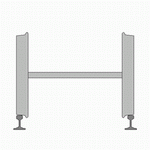
A classical hunting oscillation is a swaying motion of a railway vehicle (often called truck hunting or bogie hunting) caused by the coning action on which the directional stability of an adhesion railway depends. It arises from the interaction of adhesion forces and inertial forces. At low speed, adhesion dominates but, as the speed increases, the adhesion forces and inertial forces become comparable in magnitude and the oscillation begins at a critical speed. Above this speed, the motion can be violent, damaging track and wheels and potentially causing derailment. The problem does not occur on systems with a differential because the action depends on both wheels of a wheelset rotating at the same angular rate, although differentials tend to be rare, and conventional trains have their wheels fixed to the axles in pairs instead. Some trains, like the Talgo 350, have no differential, yet they are mostly not affected by hunting oscillation, as most of their wheels rotate independently from one another. The wheels of the power car, however, can be affected by hunting oscillation, because the wheels of the power car are fixed to the axles in pairs like in conventional bogies. Less conical wheels and bogies equipped with independent wheels that turn independently from each other and are not fixed to an axle in pairs are cheaper than a suitable differential for the bogies of a train.
The problem was first noticed towards the end of the 19th century, when train speeds became high enough to encounter it. Serious efforts to counteract it got underway in the 1930s, giving rise to lengthened trucks and the side-damping swing hanger truck. In the development of the Japanese Shinkansen, less-conical wheels and other design changes were used to extend truck design speeds above 225 km/h (140 mph). Advances in wheel and truck design based on research and development efforts in Europe and Japan have extended the speeds of steel wheel systems well beyond those attained by the original Shinkansen, while the advantage of backwards compatibility keeps such technology dominant over alternatives such as the hovertrain and maglev systems. The speed record for steel-wheeled trains is held by the French TGV, at 574.9 km/h (357 mph).
A kinematic description deals with the geometry of motion, without reference to the forces causing it, so the analysis begins with a description of the geometry of a wheel set running on a straight track. Since Newton's second law relates forces to the acceleration of bodies, the forces acting may then be derived from the kinematics by calculating the accelerations of the components. However, if these forces change the kinematic description (as they do in this case) then the results may only be approximately correct.
This kinematic description makes a number of simplifying assumptions since it neglects forces. For one, it assumes that the rolling resistance is zero. A wheelset (not attached to a train or truck), is given a push forward on a straight and level track. The wheelset starts coasting and never slows down since there are no forces (except downward forces on the wheelset to make it adhere to the track and not slip). If initially the wheelset is centered on the railroad track then the effective diameters of each wheel are the same and the wheelset rolls down the track in a perfectly straight line forever. But if the wheelset is a little off-center so that the effective diameters (or radii) are different, then the wheelset starts to move in a curve of radius R (depending on these wheelset radii, etc.; to be derived later on). The problem is to use kinematic reasoning to find the trajectory of the wheelset, or more precisely, the trajectory of the center of the wheelset projected vertically on the roadbed in the center of the track. This is a trajectory on the plane of the level earth's surface and plotted on an x-y graphical plot where x is the distance along the railroad and y is the "tracking error", the deviation of the center of the wheelset from the straight line of the railway running down the center of the track (midway between the two rails).
To illustrate that a wheelset trajectory follows a curved path, one may place a nail or screw on a flat table top and give it a push. It will roll in a circular curve because the nail or screw is like a wheelset with extremely different diameter wheels. The head is analogous to a large diameter wheel and the pointed end is like a small diameter wheel. While the nail or screw will turn around in a full circle (and more) the railroad wheelset behaves differently because as soon at it starts to turn in a curve, the effective diameters change in such a way as to decrease the curvature of the path. Note that "radius" and "curvature" refer to the curvature of the trajectory of the wheelset and not the curvature of the railway since this is perfectly straight track. As the wheelset rolls on, the curvature decreases until the wheels reach the point where their effective diameters are equal and the path is no longer curving. But the trajectory has a slope at this point (it is a straight line which crosses diagonally over the centerline of the track) so that it overshoots the centerline of the track and the effective diameters reverse (the formerly smaller diameter wheel becomes the larger diameter and conversely). This results in the wheelset moving in a curve in the opposite direction. Again it overshoots the centerline and this phenomenon continues indefinitely with the wheelset oscillating from side to side. Note that the wheel flange never makes contact with the rail. In this model, the rails are assumed to always contact the wheel tread along the same line on the rail head which assumes that the rails are knife-edge and only make contact with the wheel tread along a line (of zero width).
The train stays on the track by virtue of the conical shape of the wheel treads. If a wheelset is displaced to one side by an amount y (the tracking error), the radius of the tread in contact with the rail on one side is reduced, while on the other side it is increased. The angular velocity is the same for both wheels (they are coupled via a rigid axle), so the larger diameter tread speeds up, while the smaller slows down. The wheel set steers around a centre of curvature defined by the intersection of the generator of a cone passing through the points of contact with the wheels on the rails and the axis of the wheel set. Applying similar triangles, we have for the turn radius:
where d is the track gauge, r the wheel radius when running straight and k is the tread taper (which is the slope of tread in the horizontal direction perpendicular to the track).
Hub AI
Hunting oscillation AI simulator
(@Hunting oscillation_simulator)
Hunting oscillation
Hunting oscillation is a self-oscillation, usually unwanted, about an equilibrium. The expression came into use in the 19th century and describes how a system "hunts" for equilibrium. The expression is used to describe phenomena in such diverse fields as electronics, aviation, biology, and railway engineering.
A classical hunting oscillation is a swaying motion of a railway vehicle (often called truck hunting or bogie hunting) caused by the coning action on which the directional stability of an adhesion railway depends. It arises from the interaction of adhesion forces and inertial forces. At low speed, adhesion dominates but, as the speed increases, the adhesion forces and inertial forces become comparable in magnitude and the oscillation begins at a critical speed. Above this speed, the motion can be violent, damaging track and wheels and potentially causing derailment. The problem does not occur on systems with a differential because the action depends on both wheels of a wheelset rotating at the same angular rate, although differentials tend to be rare, and conventional trains have their wheels fixed to the axles in pairs instead. Some trains, like the Talgo 350, have no differential, yet they are mostly not affected by hunting oscillation, as most of their wheels rotate independently from one another. The wheels of the power car, however, can be affected by hunting oscillation, because the wheels of the power car are fixed to the axles in pairs like in conventional bogies. Less conical wheels and bogies equipped with independent wheels that turn independently from each other and are not fixed to an axle in pairs are cheaper than a suitable differential for the bogies of a train.
The problem was first noticed towards the end of the 19th century, when train speeds became high enough to encounter it. Serious efforts to counteract it got underway in the 1930s, giving rise to lengthened trucks and the side-damping swing hanger truck. In the development of the Japanese Shinkansen, less-conical wheels and other design changes were used to extend truck design speeds above 225 km/h (140 mph). Advances in wheel and truck design based on research and development efforts in Europe and Japan have extended the speeds of steel wheel systems well beyond those attained by the original Shinkansen, while the advantage of backwards compatibility keeps such technology dominant over alternatives such as the hovertrain and maglev systems. The speed record for steel-wheeled trains is held by the French TGV, at 574.9 km/h (357 mph).
A kinematic description deals with the geometry of motion, without reference to the forces causing it, so the analysis begins with a description of the geometry of a wheel set running on a straight track. Since Newton's second law relates forces to the acceleration of bodies, the forces acting may then be derived from the kinematics by calculating the accelerations of the components. However, if these forces change the kinematic description (as they do in this case) then the results may only be approximately correct.
This kinematic description makes a number of simplifying assumptions since it neglects forces. For one, it assumes that the rolling resistance is zero. A wheelset (not attached to a train or truck), is given a push forward on a straight and level track. The wheelset starts coasting and never slows down since there are no forces (except downward forces on the wheelset to make it adhere to the track and not slip). If initially the wheelset is centered on the railroad track then the effective diameters of each wheel are the same and the wheelset rolls down the track in a perfectly straight line forever. But if the wheelset is a little off-center so that the effective diameters (or radii) are different, then the wheelset starts to move in a curve of radius R (depending on these wheelset radii, etc.; to be derived later on). The problem is to use kinematic reasoning to find the trajectory of the wheelset, or more precisely, the trajectory of the center of the wheelset projected vertically on the roadbed in the center of the track. This is a trajectory on the plane of the level earth's surface and plotted on an x-y graphical plot where x is the distance along the railroad and y is the "tracking error", the deviation of the center of the wheelset from the straight line of the railway running down the center of the track (midway between the two rails).
To illustrate that a wheelset trajectory follows a curved path, one may place a nail or screw on a flat table top and give it a push. It will roll in a circular curve because the nail or screw is like a wheelset with extremely different diameter wheels. The head is analogous to a large diameter wheel and the pointed end is like a small diameter wheel. While the nail or screw will turn around in a full circle (and more) the railroad wheelset behaves differently because as soon at it starts to turn in a curve, the effective diameters change in such a way as to decrease the curvature of the path. Note that "radius" and "curvature" refer to the curvature of the trajectory of the wheelset and not the curvature of the railway since this is perfectly straight track. As the wheelset rolls on, the curvature decreases until the wheels reach the point where their effective diameters are equal and the path is no longer curving. But the trajectory has a slope at this point (it is a straight line which crosses diagonally over the centerline of the track) so that it overshoots the centerline of the track and the effective diameters reverse (the formerly smaller diameter wheel becomes the larger diameter and conversely). This results in the wheelset moving in a curve in the opposite direction. Again it overshoots the centerline and this phenomenon continues indefinitely with the wheelset oscillating from side to side. Note that the wheel flange never makes contact with the rail. In this model, the rails are assumed to always contact the wheel tread along the same line on the rail head which assumes that the rails are knife-edge and only make contact with the wheel tread along a line (of zero width).
The train stays on the track by virtue of the conical shape of the wheel treads. If a wheelset is displaced to one side by an amount y (the tracking error), the radius of the tread in contact with the rail on one side is reduced, while on the other side it is increased. The angular velocity is the same for both wheels (they are coupled via a rigid axle), so the larger diameter tread speeds up, while the smaller slows down. The wheel set steers around a centre of curvature defined by the intersection of the generator of a cone passing through the points of contact with the wheels on the rails and the axis of the wheel set. Applying similar triangles, we have for the turn radius:
where d is the track gauge, r the wheel radius when running straight and k is the tread taper (which is the slope of tread in the horizontal direction perpendicular to the track).