Hubbry Logo
Non-return-to-zeroNon-return-to-zeroMain
Open search
Non-return-to-zero
Community hub
Non-return-to-zero
logo
8 pages, 0 posts
0 subscribers
Be the first to start a discussion here.
Non-return-to-zero
Non-return-to-zero
from Wikipedia
The binary signal is encoded using rectangular pulse-amplitude modulation with polar NRZ(L), or polar non-return-to-zero-level code.

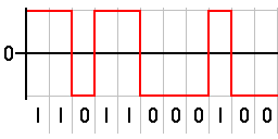
In telecommunications, a non-return-to-zero (NRZ) line code is a binary code in which ones are represented by one significant condition, usually a positive voltage, while zeros are represented by some other significant condition, usually a negative voltage, with no other neutral or rest condition.

For a given data signaling rate, i.e., bit rate, the NRZ code requires only half the baseband bandwidth required by the Manchester code (the passband bandwidth is the same). The pulses in NRZ have more energy than a return-to-zero (RZ) code, which also has an additional rest state beside the conditions for ones and zeros.

When used to represent data in an asynchronous communication scheme, the absence of a neutral state requires other mechanisms for bit synchronization when a separate clock signal is not available. Since NRZ is not inherently a self-clocking signal, some additional synchronization technique must be used for avoiding bit slips; examples of such techniques are a run-length-limited constraint and a parallel synchronization signal.

Variants

[edit]

NRZ can refer to any of the following serializer line codes:

Code
name
Alternate
name
Complete name Description
NRZ(L) NRZL Non-return-to-zero level Appears as raw binary bits without any coding. Typically binary 1 maps to logic-level high, and binary 0 maps to logic-level low. Inverse logic mapping is also a type of NRZ(L) code.
NRZ(I) NRZI Non-return-to-zero inverted Refers to either an NRZ(M) or NRZ(S) code.
NRZ(M) NRZM Non-return-to-zero mark Serializer mapping {0: constant, 1: toggle}.
NRZ(S) NRZS Non-return-to-zero space Serializer mapping {0: toggle, 1: constant}.
NRZ(C) NRZC Non-return-to-zero change

The NRZ code also can be classified as a polar or non-polar, where polar refers to a mapping to voltages of +V and −V, and non-polar refers to a voltage mapping of +V and 0, for the corresponding binary values of 1 and 0.

Unipolar non-return-to-zero level

[edit]
Unipolar NRZ(L), or unipolar non-return-to-zero level

One is represented by a DC bias on the transmission line (conventionally positive), while zero is represented by the absence of bias – the line at 0 volts or grounded. For this reason it is also known as on-off keying. In clock language, a one transitions to or remains at a biased level on the trailing clock edge of the previous bit, while zero transitions to or remains at no bias on the trailing clock edge of the previous bit. Among the disadvantages of unipolar NRZ is that it allows for long series without change, which makes synchronization difficult, although this is not unique to the unipolar case. One solution is to not send bytes without transitions. More critically, and unique to unipolar NRZ, are issues related to the presence of a transmitted DC level – the power spectrum of the transmitted signal does not approach zero at zero frequency. This leads to two significant problems: first, the transmitted DC power leads to higher power losses than other encodings, and second, the presence of a DC signal component requires that the transmission line be DC-coupled.

Bipolar non-return-to-zero level

[edit]

One is represented by one physical level (usually a positive voltage), while zero is represented by another level (usually a negative voltage). In clock language, in bipolar NRZ-level the voltage swings from positive to negative on the trailing edge of the previous bit clock cycle.

An example of this is RS-232, where one is −12 V to −5 V and zero is +5 V to +12 V.

Non-return-to-zero space

[edit]
Non-return-to-zero space
Encoder for NRZS, toggle on zero

One is represented by no change in physical level, while zero is represented by a change in physical level. In clock language, the level transitions on the trailing clock edge of the previous bit to represent a zero.

This change-on-zero is used by High-Level Data Link Control and USB. They both avoid long periods of no transitions (even when the data contains long sequences of 1 bits) by using zero-bit insertion. HDLC transmitters insert a 0 bit after 5 contiguous 1 bits (except when transmitting the frame delimiter 01111110). USB transmitters insert a 0 bit after 6 consecutive 1 bits. The receiver at the far end uses every transition — both from 0 bits in the data and these extra non-data 0 bits — to maintain clock synchronization. The receiver otherwise ignores these non-data 0 bits.

Non-return-to-zero inverted

[edit]
An example of the NRZI encoding, transition on 1
The opposite convention, transition on 0
Encoder for NRZ-M, toggle on one

Non-return-to-zero, inverted (NRZI, also known as non-return to zero IBM,[1] inhibit code,[2] or IBM code[2]) was devised by Bryon E. Phelps (IBM) in 1956.[2][3] It is a method of mapping a binary signal to a physical signal for transmission over some transmission medium. The two-level NRZI signal distinguishes data bits by the presence or absence of a transition at a clock boundary. The NRZI encoded signal can be decoded unambiguously after passing through a data path that doesn’t preserve polarity.

Which bit value corresponds to a transition varies in practice, NRZI applies equally to both. Magnetic storage generally uses the NRZ-M, non-return-to-zero mark convention: a logical 1 is encoded as a transition, and a logical 0 is encoded as no transition. The HDLC and Universal Serial Bus protocols use the opposite NRZ-S, non-return-to-zero space convention: a logical 0 is a transition, and a logical 1 is no transition. Neither NRZI encoding guarantees that the encoded bitstream has transitions.

An asynchronous receiver uses an independent bit clock that is phase synchronized by detecting bit transitions. When an asynchronous receiver decodes a block of bits without a transition longer than the period of the difference between the frequency of the transmitting and receiving bit clocks, the decoder’s bit clock is either 1 bit earlier than the encoder resulting in a duplicated bit being inserted in the decoded data stream, or the decoder’s bit clock is 1 bit later than the encoder resulting in a duplicated bit being removed from the decoded data stream. Both are referred to as bit slip denoting that the phase of the bit clock has slipped a bit period.

Forcing transitions at intervals shorter than the bit clock difference period allows an asynchronous receiver to be used for NRZI bit streams. Additional transitions necessarily consume some of the data channel’s rate capacity. Consuming no more of the channel capacity than necessary to maintain bit clock synchronization without increasing costs related to complexity is a problem with many possible solutions.

Run-length limited (RLL) encodings have been used for magnetic disk and tape storage devices using fixed-rate RLL codes that increase the channel data rate by a known fraction of the information data rate. HDLC and USB use bit stuffing: inserting an additional 0 bit before NRZ-S encoding to force a transition in the encoded data sequence after 5 (HDLC) or 6 (USB) consecutive 1 bits. Bit stuffing consumes channel capacity only when necessary but results in a variable information data rate.

Synchronized non-return-to-zero

[edit]

Synchronized NRZI (SNRZI) and group-coded recording (GCR) are modified forms of NRZI.[4] In SNRZI-M each 8-bit group is extended to 9 bits by a 1 in order to insert a transition for synchronisation.[4]

Comparison with return-to-zero

[edit]

Return-to-zero describes a line code used in telecommunications in which the signal drops (returns) to zero between each pulse. This takes place even if a number of consecutive 0s or 1s occur in the signal. The signal is self-clocking. This means that a separate clock does not need to be sent alongside the signal, but suffers from using twice the bandwidth to achieve the same data-rate as compared to non-return-to-zero format.

The zero between each bit is a neutral or rest condition, such as a zero amplitude in pulse-amplitude modulation (PAM), zero phase shift in phase-shift keying (PSK), or mid-frequency in frequency-shift keying (FSK). That zero condition is typically halfway between the significant condition representing a 1 bit and the other significant condition representing a 0 bit.

Although return-to-zero contains a provision for synchronization, it still may have a DC component resulting in baseline wander during long strings of 0 or 1 bits, just like the line code non-return-to-zero.

See also

[edit]

References

[edit]

Further reading

[edit]
[edit]
Revisions and contributorsEdit on WikipediaRead on Wikipedia
from Grokipedia
Non-return-to-zero (NRZ) is a fundamental line coding scheme in digital communications that encodes using two constant voltage levels—one for logic 1 (typically a positive or ) and one for logic 0 (typically a negative or )—without returning the signal to a zero baseline between consecutive bits of the same value. This method maintains a steady signal state throughout each bit period, enabling efficient transmission of serial data streams in systems where is provided separately from the data signal. NRZ operates on the principle of with two levels (PAM2), where each symbol represents a single bit, contrasting with multi-level schemes like PAM4 that encode multiple bits per symbol for higher data rates at the cost of . In practice, the signal remains at the assigned voltage for the full duration of the bit clock cycle, which simplifies encoding and decoding hardware but requires external to prevent bit slips during long sequences of identical bits. Key variants include unipolar NRZ, which uses a positive voltage for 1 and zero volts for 0, making it suitable for simple optical or early digital systems but prone to issues; polar NRZ, employing symmetric positive and negative voltages around zero for better immunity; and non-return-to-zero inverted (NRZI), where a transition in the signal level denotes a 1 (or 0, depending on convention) and no transition denotes the opposite, aiding clock extraction in standards like USB. Bipolar variants, such as alternate mark inversion (AMI), further enhance detection by alternating polarity for 1s while keeping 0s at zero, commonly used in for T1/E1 lines. The advantages of NRZ include its simplicity, low implementation cost, and high bandwidth efficiency, as it maximizes data rate within a given by minimizing transitions—ideal for short-reach, high-speed interconnects up to 56 Gbps. However, it suffers from a DC component in the signal , leading to baseline wander in AC-coupled systems, and lacks inherent self-clocking, necessitating techniques like (inserting transitions after several identical bits) to maintain . These limitations have prompted its evolution or replacement in ultra-high-speed applications beyond 100 Gbps, where PAM4 offers denser encoding despite increased complexity. NRZ remains widely applied in modern networking and storage technologies, including Ethernet standards (e.g., 10G to 400G variants), serial ATA/PCIe interfaces, fiber optic transceivers, and programmable logic devices like FPGAs for interconnects. It also underpins legacy protocols and industrial systems, where its reliability in noisy environments and compatibility with existing continue to provide value. As a foundational encoding method dating back to early digital telephony, NRZ exemplifies the trade-offs in line coding between simplicity, power efficiency, and robustness against transmission impairments.

Fundamentals

Definition and Principles

Non-return-to-zero (NRZ) is a binary line coding technique employed in digital communication systems, characterized by a signal that maintains a constant voltage level throughout each bit period without reverting to a zero baseline between consecutive bits of the same polarity. This approach contrasts with formats by eliminating mid-bit transitions, allowing the to stay at the full level for the entire duration TT. In NRZ encoding, a logical '1' is represented by one distinct voltage level—typically positive or high—while a logical '0' is encoded with the opposite level, such as negative or low; signal transitions occur solely at bit boundaries when the data value changes. For the fundamental NRZ-L (non-return-to-zero level) form, the waveform appears as a series of rectangular pulses, where each pulse spans the bit interval TT with amplitude ±V\pm V, and no pulse returns to zero unless dictated by a bit flip. For example, a bit sequence like 10110 would produce a waveform toggling between +V and -V at the start of the second, third, and fifth bits, remaining steady otherwise; the bit timing is synchronized to this period TT, resulting in a baud rate equivalent to the bit rate for binary transmission. The core principle of NRZ stems from its avoidance of return-to-zero pulses, which sustains signal energy across the bit duration but can introduce a DC component, particularly in unbalanced data patterns with long runs of identical bits, leading to potential baseline wander in AC-coupled receivers. This DC offset arises because the average signal power may not be zero, complicating transmission over media sensitive to low-frequency components. NRZ's simplicity is evident in its use of just two signal levels, facilitating bandwidth-efficient transmission where the required bandwidth is roughly half the due to the rectangular pulse shape's spectral characteristics, primarily concentrated around the 1/(2T)1/(2T). This efficiency makes NRZ suitable for applications prioritizing straightforward implementation over self-clocking features.

Historical Context

Non-return-to-zero (NRZ) encoding emerged in the mid-20th century as a fundamental for digital communication, with roots tracing back to early systems and the nascent field of computer interfaces. Basic binary signaling in , such as Émile Baudot's 1874 five-bit for printing telegraphs, laid conceptual groundwork by representing data through persistent voltage levels without returning to a neutral state, akin to unipolar NRZ principles. By the late , NRZ gained prominence in early computer storage, where Engineering Research Associates (ERA) evaluated it against (RZ) for magnetic , favoring NRZ for its efficiency in reducing signal transitions and enabling higher data densities. A key milestone occurred in the 1950s with 's adoption of NRZ-based encoding in its pioneering systems, marking a shift from earlier recording methods to support faster data rates in commercial computing. In 1952, introduced the Model 726 for the computer, utilizing a variant called non-return-to-zero inverted (NRZI)—a form of NRZ where transitions represent data bits—to achieve recording densities up to 100 bits per inch, replacing less efficient phase-shift codes and enabling storage capacities of about 2 million characters per reel. This innovation, developed under engineer Byron Phelps, facilitated reliable sequential data access in early mainframes, influencing subsequent tape standards across the industry. Through the 1960s and 1970s, NRZ evolved within emerging standards, emphasizing hardware simplicity for widespread digital interfacing. The Electronic Industries Association (EIA) formalized in 1962 as a recommended standard for serial data transmission, employing NRZ encoding with to define voltage levels for logical ones and zeros, which streamlined connections between (DTE) and (DCE) in teletype and applications. By the mid-1970s, NRZ was integrated into international telecommunication frameworks, with its formalization in Recommendation G.703 (first published in December 1972) specifying physical and electrical characteristics for hierarchical digital interfaces in (PDH) systems, supporting bit rates from 64 kbit/s upward. In the , the transition to and local area networks prompted the development of NRZ variants to mitigate issues like accumulation, which could degrade over long distances or unbalanced bit patterns. Bipolar NRZ formats, such as alternate mark inversion (AMI), were refined for fiber optic transmission in telecommunication standards, ensuring no net DC component by alternating positive and negative pulses for ones. Similarly, in Ethernet evolution, biphase codes like encoding were used in fiber-based media such as 10BASE-F, standardized in IEEE 802.3j ( but developed in the late ), to balance spectra, provide self-clocking, and enhance compatibility with optical transceivers.

Encoding Methods

Basic NRZ Signaling

In basic non-return-to-zero (NRZ) signaling, the NRZ-L (level) variant serves as the standard encoding method, where a binary 1 is represented by a constant level (typically +V) sustained throughout the entire bit period T_b, and a binary 0 is represented by a constant low voltage level (typically 0 V or -V, depending on the polarity scheme). Voltage transitions occur exclusively at bit boundaries when the successive bit values differ; no mid-bit transitions happen, distinguishing NRZ from schemes that return to a zero baseline. This level-based encoding ensures a simple, direct mapping of to levels without intermediate returns. The timing of NRZ-L signals aligns with a reference bit clock, where each bit occupies a fixed duration T_b, enabling the receiver to sample the voltage level at the appropriate or boundary. In a timing , a sequence like 1010 would show alternating high and low levels with transitions at every bit edge, providing frequent edges for . Conversely, consecutive identical bits, such as 1111, produce a flat high line with no transitions across multiple T_b periods, or 0000 yields a flat low line; this absence of edges in long runs (e.g., more than a few bits) complicates , as receivers rely on transitions to extract and maintain bit timing, potentially leading to drift without auxiliary mechanisms. Mathematically, the NRZ-L signal S(t) during a given bit interval [nT_b, (n+1)T_b) is defined as: S(t) = \begin{cases} V_\text{high} & \text{if the } n\text{th bit is 1} \\ V_\text{low} & \text{if the } n\text{th bit is 0} \end{cases} $$ where n is the bit index, and the level remains constant over T_b. This formulation highlights the piecewise constant nature of the signal.[](https://www.cise.ufl.edu/~nemo/cen4500/coding.html) NRZ-L requires a minimum theoretical bandwidth of approximately 1/(2T_b) or R_b/2 (where R_b is the [bit rate](/page/Bit_rate)) for ideal transmission, as the signal's power spectrum is concentrated up to half the bit rate due to its rectangular pulse shape; this is lower than the bandwidth demands of modulated schemes like [amplitude-shift keying](/page/Amplitude-shift_keying), which often exceed R_b to accommodate carrier frequencies. However, practical implementations may need slightly more bandwidth to mitigate [intersymbol interference](/page/Intersymbol_interference) from non-ideal filtering.[](https://vtechworks.lib.vt.edu/bitstream/handle/10919/11110/Chongburee_Dissertation.pdf?sequence=1&isAllowed=y) ### Comparison to Return-to-Zero Return-to-zero (RZ) encoding is a line coding scheme in which the signal returns to the zero baseline midway through each bit period, irrespective of the bit value, typically using a [pulse width](/page/Pulse_width) of half the bit period (50% [duty cycle](/page/Duty_cycle)).[](https://web.stanford.edu/class/ee179/lectures/notes14.pdf)[](https://www.cs.nmt.edu/~cs353/Lectures/Lecture_04_Digital_and_Analog_Transmission_Ch04.pdf) In contrast, non-return-to-zero (NRZ) encoding maintains a constant voltage level throughout the entire bit period for each bit, with the duty cycle optionally at 50% but not mandating a mid-bit return to zero.[](https://web.stanford.edu/class/ee179/lectures/notes14.pdf) This fundamental structural difference results in NRZ allowing for sustained flat signal levels during sequences of identical bits, while RZ enforces a transition to zero in every bit interval.[](https://www.cs.nmt.edu/~cs353/Lectures/Lecture_04_Digital_and_Analog_Transmission_Ch04.pdf) Waveform comparisons illustrate these distinctions clearly: an NRZ signal for a sequence like 11100 might exhibit prolonged high or low plateaus without interruptions, potentially spanning multiple bit periods, whereas an equivalent RZ [waveform](/page/Waveform) would feature short pulses (e.g., high for half the period followed by zero for the remainder in a '1' bit) separated by guaranteed zero intervals, ensuring a mid-bit transition in every [symbol](/page/Symbol).[](https://web.stanford.edu/class/ee179/lectures/notes14.pdf) These RZ transitions facilitate easier clock extraction, as the regular zero returns create a predictable timing pattern, unlike NRZ's potential for long runs of identical bits that lack transitions and challenge [phase-locked loop](/page/Phase-locked_loop) (PLL) recovery.[](https://www.cs.nmt.edu/~cs353/Lectures/Lecture_04_Digital_and_Analog_Transmission_Ch04.pdf)[](https://web.stanford.edu/class/ee179/lectures/notes14.pdf) Regarding bandwidth, RZ demands approximately twice that of NRZ for the same [bit rate](/page/Bit_rate), as the narrower half-period pulses introduce faster transitions and higher-frequency components, effectively doubling the [fundamental frequency](/page/Fundamental_frequency) from roughly $ R_b / 2 $ (where $ R_b $ is the [bit rate](/page/Bit_rate)) in NRZ to $ R_b $ in RZ.[](https://web.stanford.edu/class/ee179/lectures/notes14.pdf) This increased spectral occupancy makes RZ less efficient for bandwidth-constrained channels, though its [synchronization](/page/Synchronization) benefits have historically outweighed this drawback in certain applications. RZ's synchronization advantage stems from its inherent transitions every bit period, which enable robust PLL locking even without additional data patterns, addressing NRZ's vulnerability to synchronization loss during extended runs of ones or zeros.[](https://web.stanford.edu/class/ee179/lectures/notes14.pdf)[](https://www.cs.nmt.edu/~cs353/Lectures/Lecture_04_Digital_and_Analog_Transmission_Ch04.pdf) Historically, RZ found use in early [pulse-code modulation](/page/Pulse-code_modulation) (PCM) systems and magnetic disk drives from the 1940s to 1950s, where transition-based timing recovery was essential, but NRZ has since been favored in modern systems for its superior bandwidth efficiency and [simplicity](/page/Simplicity).[](https://web.stanford.edu/class/ee179/lectures/notes14.pdf) ## Variants ### Unipolar NRZ Unipolar NRZ, also referred to as unipolar non-return-to-zero level (NRZ-L), is a binary line coding scheme where a logic 1 is encoded as a constant positive voltage level (typically denoted as +V) throughout the bit period, while a logic 0 is encoded as zero voltage (0 V).[](https://www.ee.iitb.ac.in/~sarva/courses/EE703/2013/Slides/PSDofModulatedSignals.pdf) This encoding avoids negative voltage levels entirely, with transitions occurring only between 0 V and +V at bit boundaries depending on the data sequence, or remaining steady at either level for consecutive identical bits. In terms of signal characteristics, unipolar NRZ exhibits a significant DC component because the average voltage across the signal is directly proportional to the density of 1s in the [data stream](/page/Data_stream); for a random binary sequence with equal probability of 0s and 1s, the average voltage is V/2, rising to V for an all-1s sequence and dropping to 0 V for an all-0s sequence.[](https://www.ee.iitb.ac.in/~sarva/courses/EE703/2013/Slides/PSDofModulatedSignals.pdf) This [DC bias](/page/DC_bias) leads to baseline wander in AC-coupled transmission systems, where capacitors or transformers block the DC component, causing the received signal baseline to drift during long runs of identical bits and potentially degrading detection accuracy. A representative [waveform](/page/Waveform) for the bit sequence 1010 in unipolar NRZ consists of alternating full-height positive pulses for each 1 and flat zero levels for each 0, resulting in a series of isolated pulses separated by zero-voltage intervals. The power [spectral density](/page/Spectral_density) (PSD) of unipolar NRZ signals underscores the presence of low-frequency components, given by the formula: S(f) = \frac{A^2 T_b}{4} \mathrm{sinc}^2(f T_b) + \frac{A^2}{4} \delta(f) where $A$ is the signal [amplitude](/page/Amplitude), $T_b$ is the bit duration, $\mathrm{sinc}(x) = \sin(\pi x)/(\pi x)$, and the delta function $\delta(f)$ represents the DC component.[](https://www.ee.iitb.ac.in/~sarva/courses/EE703/2013/Slides/PSDofModulatedSignals.pdf) Unipolar NRZ was used in early electrical and optical digital systems before the adoption of bipolar schemes to mitigate DC-related issues.[](https://www.ee.iitb.ac.in/~sarva/courses/EE703/2013/Slides/PSDofModulatedSignals.pdf) ### Bipolar NRZ Bipolar NRZ, also known as alternate mark inversion (AMI), is a line coding technique that employs three voltage levels to represent [binary data](/page/Binary_data): zero for a logical 0 and alternating positive (+V) and negative (-V) levels for successive logical 1s.[](https://web.stanford.edu/class/ee179/lectures/notes14.pdf) This scheme maintains a non-return-to-zero format, where each bit occupies the full bit duration without returning to a baseline midway.[](https://personal.utdallas.edu/~torlak/courses/ee4367/lectures/CodingI.pdf) In the encoding process, a logical 0 is transmitted as 0 V, while each logical 1 triggers a [pulse](/page/Pulse) whose polarity inverts relative to the previous 1, regardless of intervening 0s. For instance, in a bit [sequence](/page/Sequence) of 110, the first 1 is encoded as +V across the entire bit period, the second 1 as -V across its bit period, and the 0 as 0 V; this results in transitions at bit boundaries for consecutive 1s due to the polarity flip.[](https://web.stanford.edu/class/ee179/lectures/notes14.pdf)[](https://personal.utdallas.edu/~torlak/courses/ee4367/lectures/CodingI.pdf) The alternation prevents long runs of the same polarity, though sequences of 0s produce no signal transitions. The alternating pulses in bipolar NRZ achieve inherent DC balance, yielding an average voltage of zero over random data patterns with equal probability of 0s and 1s, which mitigates baseline wander and enables reliable transmission through AC-coupled systems like transformers and extended copper cables.[](https://web.stanford.edu/class/ee179/lectures/notes14.pdf)[](https://www.dcbnet.com/notes/9611t1.html) This contrasts with unipolar NRZ, where a persistent DC component arises from unbalanced positive pulses.[](https://personal.utdallas.edu/~torlak/courses/ee4367/lectures/CodingI.pdf) The power [spectral density](/page/Spectral_density) (PSD) of bipolar NRZ exhibits a null at DC (f=0), concentrating energy at higher frequencies and reducing low-frequency interference. The PSD is given by S(f) = \frac{V^2 T_b}{2} \sinc^2(\pi f T_b) \sin^2(\pi f T_b), where $V$ is the [pulse](/page/Pulse) amplitude, $T_b$ is the bit duration, and $\sinc(x) = \sin(\pi x)/(\pi x)$; this form arises from the [autocorrelation](/page/Autocorrelation) properties of the alternating marks and the rectangular [pulse](/page/Pulse) shape.[](https://web.stanford.edu/class/ee179/lectures/notes14.pdf) Bipolar NRZ was standardized by AT&T in the 1960s for the DS1 format in T1 and E1 telephony systems, where it supports 1.544 Mbps transmission over twisted-pair lines while facilitating timing recovery and error detection through bipolar violations.[](https://www.dcbnet.com/notes/9611t1.html) ### NRZ Space NRZ-S, or non-return-to-zero space, is a line coding variant where a binary 1 is encoded by maintaining the current voltage level without any transition, while a binary 0 is encoded by inverting the voltage level at the end of the bit period.[](https://cdnx.uobabylon.edu.iq/lectures/Ye5gfshqTEO8lV3Dbb6hGQ.pdf) This differential encoding scheme ensures that transitions occur specifically in response to 0-bits, distinguishing it from level-based NRZ methods by tying signal changes to the "space" (logical 0) rather than the data value itself.[](https://web.eece.maine.edu/~vweaver/classes/ece435_2018f/ece435_lec18.pdf) To illustrate, consider the bit sequence 11010, assuming an initial [high voltage](/page/High_voltage) level. The first two 1-bits maintain the high level with no transition. The following 0-bit triggers an inversion to low at its end. The subsequent 1-bit holds the low level steady. The final 0-bit then inverts back to high at its conclusion. This results in a [waveform](/page/Waveform) with flat segments during 1-bits and edges only at the boundaries of 0-bits, as shown in the simplified representation below: | Bit Position | Data Bit | Signal Level | Transition? | |--------------|----------|--------------|-------------| | 1 | 1 | High | No | | 2 | 1 | High | No | | 3 | 0 | High to Low | Yes (end) | | 4 | 1 | Low | No | | 5 | 0 | Low to High | Yes (end) | Such encoding produces a signal with potential long runs of constant voltage during sequences of consecutive 1s, but guaranteed edges for each 0.[](https://cdnx.uobabylon.edu.iq/lectures/Ye5gfshqTEO8lV3Dbb6hGQ.pdf) The primary purpose of NRZ-S is to facilitate [clock recovery](/page/Clock_recovery) at the receiver by providing predictable transitions tied to 0-bits, allowing [synchronization](/page/Synchronization) even in data streams with infrequent 0s, as each such bit resets the receiver's timing reference.[](https://cdnx.uobabylon.edu.iq/lectures/Ye5gfshqTEO8lV3Dbb6hGQ.pdf) In the [waveform](/page/Waveform), this manifests as space-signaling transitions that enable phase-locked loops or edge detectors to extract the bit clock, though extended 1-bit runs can still challenge [synchronization](/page/Synchronization) without additional measures like [bit stuffing](/page/Bit_stuffing). As a counterpart to NRZ mark (which transitions on 1s), NRZ-S is suited for scenarios expecting sparse 0s to maintain signal edges.[](https://web.eece.maine.edu/~vweaver/classes/ece435_2018f/ece435_lec18.pdf) NRZ-S finds application in early serial protocols such as USB low-speed modes (1.5 Mb/s), where it supports synchronization through transitions on 0s, augmented by bit stuffing to prevent long 1-runs and ensure periodic edges.[](https://web.eece.maine.edu/~vweaver/classes/ece435_2018f/ece435_lec18.pdf) It is also employed in HDLC (High-Level Data Link Control) for reliable frame transmission over serial links. In telemetry systems, particularly under IRIG Standard 106, NRZ-S is used in PCM/FM and PCM/PM configurations for aerospace data links, handling long zero strings while maintaining bit synchronizer performance at rates up to 900 kb/s and providing polarity insensitivity for robust BER in high-SNR environments (≥15 dB).[](https://apps.dtic.mil/sti/pdfs/AD1038198.pdf) ### NRZ Inverted Non-return-to-zero inverted (NRZ-I), also known as NRZI, is a differential line coding scheme in which a binary 1 is encoded by a transition (inversion) of the signal level from its current state, while a binary 0 is encoded by maintaining the current signal level with no transition.[](https://book.systemsapproach.org/direct/encoding.html) The encoding begins from an arbitrary reference level, such as low or high, and subsequent bits determine whether the level flips or stays the same based solely on the presence of 1s.[](https://www.cs.cmu.edu/~prs/15-441-F13/lectures/05-datalink.pdf) This method contrasts with level-based encodings by relying on changes rather than absolute voltages, making it suitable for media where polarity inversion is detectable, such as magnetic recording.[](http://www.bitsavers.org/pdf/ibm/3480/3480_Recording-Channel_Development_Jun85.pdf) An example encoding sequence illustrates the process: starting from a low level, the bit pattern 101 would produce a transition to high for the first 1, remain high for the 0, and then transition to low for the second 1, resulting in the waveform: low-to-high transition, steady high, high-to-low transition. Transitions thus occur exclusively at bit positions corresponding to 1s, ensuring that the signal level at any point reflects the cumulative number of 1s encountered modulo 2 from the starting level.[](https://book.systemsapproach.org/direct/encoding.html) The differential nature of NRZ-I enables inherent error detection, particularly for single-bit errors within a fixed-length block or character. A single-bit flip—whether from 0 to 1 (adding an spurious transition) or 1 to 0 (omitting an expected transition)—alters the parity of transitions, causing the signal level at the block's end to mismatch the expected level if the receiver knows the starting state or uses block-level validation, allowing detection without additional parity bits. This property enhances reliability in noisy environments by flagging odd-numbered errors that propagate as inverted interpretations until corrected. Regarding synchronization, NRZ-I performs better than basic NRZ for long runs of 1s, as each 1 generates a transition to aid [clock recovery](/page/Clock_recovery), but it fares similarly or worse for long runs of 0s, where the absence of transitions can lead to bit-slip or loss of timing alignment, often requiring external clocking or [scrambling](/page/Scrambling) to mitigate.[](https://book.systemsapproach.org/direct/encoding.html) NRZ-I has been employed in IBM's 3480 [magnetic tape](/page/Magnetic_tape) drives, where it supports high-density recording through flux reversals on 1s, contributing to the system's robustness against media defects.[](http://www.bitsavers.org/pdf/ibm/3480/3480_Recording-Channel_Development_Jun85.pdf) It is also utilized in certain satellite communications, such as [telemetry](/page/Telemetry) and [automatic identification system](/page/Automatic_identification_system) (AIS) receivers on small satellites, leveraging its error detection and transition-based encoding for reliable data transmission over variable channels.[](https://digitalcommons.usu.edu/cgi/viewcontent.cgi?article=1565&context=smallsat) ### Synchronized NRZ Synchronized NRZ refers to an enhanced form of non-return-to-zero (NRZ) line coding that incorporates [synchronization](/page/Synchronization) features, such as [data scrambling](/page/Scrambling) or the insertion of fixed patterns at regular intervals, to generate periodic signal transitions and mitigate extended periods of constant voltage levels in data streams. This approach ensures that [clock recovery](/page/Clock_recovery) circuits, typically phase-locked loops (PLLs), can maintain lock even during sequences of identical bits, which pose a challenge in standard NRZ by lacking sufficient edges for timing extraction.[](https://book.systemsapproach.org/direct/encoding.html) In terms of encoding, synchronized NRZ builds on basic NRZ by applying techniques like bit-oriented [scrambling](/page/Scrambling) or deliberate sync bit insertion; for instance, a 1-0-1 pattern may be added every 16 bits to force transitions and provide reference points for baud rate alignment.[](https://erg.abdn.ac.uk/users/gorry/eg3576/serial-synch.html) The primary purpose is to overcome NRZ's vulnerability to run-length limited sequences, thereby guaranteeing reliable PLL [synchronization](/page/Synchronization) and reducing bit error rates in high-speed serial links.[](https://www.sciencedirect.com/topics/engineering/clock-recovery) A key example appears in Synchronous Digital Hierarchy (SDH) and Synchronous Optical Networking (SONET) standards, where NRZ encoding is employed alongside framing bytes in the overhead section—such as the A1 and A2 bytes set to 0xF6—to deliver fixed sync patterns that facilitate frame alignment and [clock recovery](/page/Clock_recovery).[](https://www.electrosofts.com/sonet/scrambling) This was developed in the [1980s](/page/1980s) for high-speed optical links and later extended in frameworks like the [ITU-T](/page/ITU-T) G.709 Optical Transport Network (OTN) standard, which uses similar NRZ-based synchronization for rates up to 40 Gbit/s to support robust data transport.[](http://ww1.microchip.com/downloads/en/DeviceDoc/2170438_Microsemi_otn_b100G_tutorial_FlexO_302441.pdf)[](https://www.albedotelecom.com/src/lib/BK-SONET-SDH.pdf) ## Applications ### Data Storage Media Non-return-to-zero inverted (NRZI) encoding, a variant of NRZ principles, played a pivotal role in early magnetic tape storage systems, particularly in IBM's 7-track tape formats introduced in the [1950s](/page/1950s). These systems utilized NRZI to record [data](/page/Data) on half-inch-wide [magnetic tape](/page/Magnetic_tape), achieving linear densities of up to 800 bits per inch (bpi) by the early [1960s](/page/1960s). The NRZI implementation saturated the tape in either positive or negative directions, enhancing signal detection by providing transitions for [clock recovery](/page/Clock_recovery) while reducing baseline wander during readout. This approach enabled reliable archival storage for mainframe computers, with the [IBM](/page/IBM) 729 [tape drive](/page/Tape_drive) supporting NRZI modes for compatibility across densities from 200 to 800 bpi.[](https://bitsavers.trailing-edge.com/pdf/ibm/magtape/729/223-6988_729_CE_Mar62.pdf)[](http://www.quadibloc.com/comp/tapeint.htm) In hard disk drives, NRZ formed the basis for bit [serialization](/page/Serialization) in early implementations, often integrated with [modified frequency modulation](/page/Modified_frequency_modulation) (MFM) and run-length limited (RLL) schemes to optimize storage [density](/page/Density) while maintaining [clock synchronization](/page/Clock_synchronization). For instance, MFM encoding, a derivative that inserts clock bits into NRZ streams to prevent long runs of zeros, was standard in drives from the 1970s onward, allowing capacities like 20 MB per platter in MFM mode or 30 MB in RLL variants on the same hardware. Although later superseded by partial response maximum likelihood (PRML) detection in the 1990s for higher densities, NRZ's simple level-based representation remained foundational for serializing data onto magnetic platters in systems like the [IBM](/page/IBM) 3340 [Winchester](/page/Winchester) drive.[](https://faculty.cs.niu.edu/~berezin/463/lec/bus/transferC.html)[](http://www.bitsavers.org/pdf/csc/CSC_Hard_Drive_Bible_7th_Edition_1994.pdf) Optical disc technologies, such as [CD-ROM](/page/CD-ROM), employed NRZ in their data channels through derived formats like [eight-to-fourteen modulation](/page/Eight-to-fourteen_modulation) (EFM), which maps 8-bit [data](/page/Data) to 14-bit symbols while adhering to RLL constraints—specifically limiting runs to enforce transitions for reliable pit-and-land detection. The EFM scheme, a (2,10) RLL variant with merge bits to avoid excessive runs, converts the resulting binary stream to NRZ signaling before NRZI modulation for laser recording, ensuring minimal [intersymbol interference](/page/Intersymbol_interference) at densities supporting 540 MB per disc. This NRZ-derived approach boosted read speeds to 1.2 Mbps in early [CD-ROM](/page/CD-ROM) drives by the [1980s](/page/1980s). NRZ's efficiency also extended to higher-density magnetic tapes, such as 9-track formats reaching 6250 bpi in the [1970s](/page/1970s) via group code recording (GCR) with NRZI, which dramatically increased archival capacities to over 50 MB per 2400-foot reel.[](https://www.researchgate.net/publication/3234561_A_survey_of_codes_for_optical_disk_recording)[](https://www.govinfo.gov/content/pkg/GOVPUB-C13-e47db946f90bfb615ae1d49fae7fee44/pdf/GOVPUB-C13-e47db946f90bfb615ae1d49fae7fee44.pdf) However, NRZ's susceptibility to synchronization loss during long sequences of identical bits prompted a shift to Manchester encoding in some floppy disk systems, where mid-bit transitions embed clock information to maintain timing without separate signals. This transition addressed NRZ's limitations in variable-speed media like 5.25-inch floppies, enabling reliable double-density recording at 300 KB per diskette in IBM PC compatibles.[](https://electronics.stackexchange.com/questions/356699/what-is-problem-with-nrz-and-how-manchester-line-coding-handles-out-of-sync-tx-a)[](https://faculty.cs.niu.edu/~berezin/463/lec/bus/transferC.html) ### Telecommunications Protocols Non-return-to-zero (NRZ) signaling has been a foundational element in [telecommunications](/page/Telecommunications) protocols since the early 1970s, providing a reliable method for serial data transmission over both copper and optical media in wide-area networks. The ITU-T Recommendation G.703, first established in 1972, defines the physical and electrical characteristics of hierarchical digital interfaces using NRZ formats, supporting bit rates from 64 kbps up to 2 Mbps to enable structured [multiplexing](/page/Multiplexing) in public switched telephone networks.[](https://www.itu.int/rec/T-REC-G.703/en) This standard ensures compatibility across international digital hierarchies by specifying NRZ as the primary [line code](/page/Line_code) for balanced [coaxial](/page/Coaxial) or twisted-pair connections, facilitating [synchronization](/page/Synchronization) and error detection in real-time transmission environments.[](https://www.itu.int/rec/T-REC-G.703/en) In T1 and E1 carrier systems, bipolar NRZ-alternate mark inversion (NRZ-AMI) serves as the standard [line code](/page/Line_code), operating at 1.544 Mbps for T1 (North American) and 2.048 Mbps for E1 (European) to aggregate multiple voice channels over twisted-pair copper lines. To mitigate long sequences of zeros that could disrupt timing recovery, binary 8-zero substitution (B8ZS) is employed in T1 systems, replacing eight consecutive zeros with a specific bipolar violation pattern that maintains DC balance without altering [data integrity](/page/Data_integrity).[](https://download.tek.com/document/2GW_15658_0_0.pdf) Similarly, E1 implementations under G.703 use high-density bipolar 3-zero (HDB3) coding as a variant of bipolar NRZ-AMI for zero suppression, ensuring adequate transition density for clock extraction over distances up to several kilometers.[](https://www.itu.int/rec/dologin_pub.asp?lang=e&id=T-REC-G.703-198811-S!!PDF-E&type=items) These techniques, defined in ANSI T1.403 for T1 and ITU G.703/G.704 for E1, have enabled robust deployment in legacy digital trunks while supporting migration to higher-capacity hierarchies.[](https://www.gl.com/Presentations/T1E1-Overview-Presentation.pdf) The Synchronous Optical Network (SONET) and Synchronous Digital Hierarchy (SDH) standards incorporate NRZ encoding within the [STS-1](/page/STS-1) (Synchronous Transport Signal level 1) frame [payload](/page/Payload) at 51.84 Mbps, where the serial [data stream](/page/Data_stream) is formatted for optical [transport](/page/Transport) with frame-aligned [synchronization](/page/Synchronization). To prevent long runs of identical bits that could impair receiver timing, a self-synchronous [scrambler](/page/Scrambler) based on the [polynomial](/page/Polynomial) $x^{43} + 1$ is applied to the NRZ [payload](/page/Payload), randomizing the bit sequence while preserving the underlying [data structure](/page/Data_structure) as outlined in [ITU-T](/page/ITU-T) G.707. Synchronized NRZ variants are briefly referenced in SONET section overhead for pointer adjustments, though full details appear in dedicated signaling discussions. This scrambling ensures reliable recovery in multi-gigabit optical rings, forming the backbone of metropolitan and long-haul telecom infrastructures since the [1980s](/page/1980s). In [optical fiber](/page/Optical_fiber) [telecommunications](/page/Telecommunications), NRZ on-off keying (NRZ-OOK) remains prevalent for direct-detection systems, particularly in 10G transport where it achieves error-free transmission over hundreds of kilometers using standard single-mode fiber without advanced processing. For higher rates up to 100G, [digital signal processing](/page/Digital_signal_processing) (DSP) equalization compensates for chromatic dispersion and bandwidth limitations, enabling 4 × 25 Gb/s NRZ-OOK over 160 km with 10G-class [optics](/page/Optics) and receiver-side dispersion compensation.[](https://ieeexplore.ieee.org/document/8358005) These implementations, compliant with [ITU-T](/page/ITU-T) G.709 for optical transport networks, leverage NRZ-OOK's simplicity for cost-effective upgrades in dense [wavelength-division multiplexing](/page/Wavelength-division_multiplexing) (DWDM) systems. NRZ's adaptability has driven its evolution from copper-based protocols like T1/E1 to fiber-optic domains, where it persists in hybrid formats alongside [pulse amplitude modulation with 4 levels (PAM4)](/page/Pulse-amplitude_modulation) for rates exceeding 400G. In 400G optical transceivers, NRZ transitions to [PAM4](/page/Pulse-amplitude_modulation) to double [spectral efficiency](/page/Spectral_efficiency) per lane, reducing baud rates from 25 Gbaud (NRZ) to 53 Gbaud ([PAM4](/page/Pulse-amplitude_modulation)) while maintaining compatibility with existing fiber infrastructure through DSP-enhanced equalization.[](https://www.ieee802.org/3/bs/public/14_05/bhoja_3bs_01_0514.pdf) This progression, standardized in IEEE 802.3bs, underscores NRZ's enduring role in scaling telecom capacities from legacy hierarchies to terabit-era optical networks.[](https://www.ieee802.org/3/bs/public/14_05/bhoja_3bs_01_0514.pdf) ### Network Interfaces Non-return-to-zero (NRZ) encoding plays a key role in various network interfaces, particularly in [serial communication](/page/Serial_communication) and high-speed Ethernet standards, where it enables reliable data transmission over electrical and optical media by maintaining signal levels without returning to a zero state between bits. In these interfaces, NRZ is often combined with additional coding schemes like block encoding or inversion to address [synchronization](/page/Synchronization) and error detection needs.[](https://www.usb.org/sites/default/files/bwpaper2.pdf) RS-232 and RS-485 interfaces, commonly used for UART-based [serial communication](/page/Serial_communication) in computer networking, employ NRZ-level (NRZ-L) encoding, where a logical '1' is represented by a [high voltage](/page/High_voltage) level and a '0' by a low level, with the idle state maintained at a high (mark) level. These standards support asynchronous data rates up to 115.2 kbps for [RS-232](/page/RS-232) over short distances and higher rates for [RS-485](/page/RS-485) in multi-drop configurations, leveraging NRZ-L for its simplicity in point-to-point and multi-point links.[](http://ibiblio.org/kuphaldt/socratic/model/mod_232_422_485.pdf)[](https://www.ti.com/lit/pdf/slla272) In Ethernet standards, while 10BASE-T primarily uses [Manchester](/page/Manchester) encoding—a [differential form](/page/Differential_form) derived from NRZ principles for self-clocking over twisted-pair cabling—higher-speed variants incorporate NRZ more directly. For instance, 1000BASE-T, defined in IEEE 802.3ab, uses [pulse](/page/Pulse) [amplitude](/page/Amplitude) modulation-5 (PAM-5) line coding across four twisted pairs to achieve 1 Gbps full-duplex transmission, with 4D trellis coding and 8B1Q4 block encoding for [symbol](/page/Symbol) generation.[](https://www.flukenetworks.com/knowledge-base/applicationstandards-articles-copper/mhz-vs-mbits-and-encoding)[](https://cableplusinc.com/wp-content/uploads/CPI-PDFs/Atras/techincal-info/IEEE-802.3ab-1000BASE-T-Gigabit-Ethernet-Updated-Nov-2015.pdf) USB interfaces at low (1.5 Mbps) and full (12 Mbps) speeds utilize NRZ-inverted (NRZ-I) encoding with [bit stuffing](/page/Bit_stuffing) to ensure frequent transitions for [clock recovery](/page/Clock_recovery), where a '1' bit is signaled by no level change and a '0' by a transition on the differential D+/D- lines. This approach, standardized in the USB 2.0 specification, maintains compatibility with legacy devices while preventing long runs of identical bits that could disrupt synchronization.[](https://www.usb.org/sites/default/files/bwpaper2.pdf) Gigabit Ethernet over fiber, such as 1000BASE-SX, employs NRZ line coding at 1.25 Gbps (including overhead) combined with 8B/10B block encoding to balance DC levels and provide sufficient transitions, as specified in IEEE 802.3z for short-range multimode fiber links up to 550 meters.[](https://staff.uz.zgora.pl/amajczak/sieci-komputerowe/Module7.pdf) In modern backplane applications, NRZ remains prevalent in Serializer/Deserializer (SerDes) interfaces for Ethernet, supporting data rates up to 28 Gbps per lane with techniques like pre-emphasis to compensate for channel losses and inter-symbol interference in high-density printed circuit boards. These implementations, aligned with IEEE 802.3 standards for backplane Ethernet, enable efficient aggregation in switches and routers while transitioning to higher-order modulations like PAM4 beyond 28 Gbps.[](http://cc.ee.ntu.edu.tw/~jrilee/publications/56G_NRZPAM4_J.pdf)[](https://www.link-pp.com/blog/nrz-vs-pam4-modulation-comparison.html) ## Performance Characteristics ### Advantages Non-return-to-zero (NRZ) encoding is prized for its inherent simplicity in digital communication systems, requiring only two distinct voltage levels and straightforward transceivers that minimize hardware complexity and associated costs.[](https://www.utdallas.edu/~torlak/courses/ee4367/lectures/CodingI.pdf) This design eliminates the need for complex [pulse shaping](/page/Pulse_shaping) or [return-to-zero](/page/Return-to-zero) transitions, enabling easier implementation in both electrical and optical domains.[](https://www.techtarget.com/whatis/definition/NRZ-non-return-to-zero) A core strength of NRZ lies in its bandwidth efficiency, as it fully utilizes the entire bit period for signal representation, achieving a direct equivalence between [bit rate](/page/Bit_rate) and [baud](/page/Baud) rate without wasteful idle periods.[](https://www.techtarget.com/whatis/definition/NRZ-non-return-to-zero) This characteristic makes NRZ particularly well-suited for high-speed serial links where maximizing throughput per unit bandwidth is essential. NRZ also excels in power efficiency due to its constant [amplitude](/page/Amplitude) levels throughout each bit duration, which reduce switching losses and [energy](/page/Energy) dissipation compared to pulsed coding formats that involve frequent transitions.[](https://www.ijraset.com/best-journal/comparison-of-rz-and-nrz-modulation-techniques-by-varying-duty-cycle) In practical deployments, this translates to lower overall power consumption in transceivers, supporting energy-efficient operation in dense networking environments. In high-speed optical applications, NRZ supports data rates up to 100 Gbps with minimal encoding overhead, such as in [100 Gigabit Ethernet](/page/100_Gigabit_Ethernet) using four 25 Gbps lanes, facilitating its adoption in [data center](/page/Data_center) interconnects.[](https://www.qsfptek.com/qt-news/nrz-and-pam4-explore-the-difference.html) The balanced bipolar variant of NRZ further enhances robustness by providing substantial noise margins through symmetric positive and negative pulses, allowing reliable transmission over extended distances without significant degradation.[](https://people.ece.ubc.ca/~edc/3525.jan2017/lectures/lec5.pdf) ### Limitations and Mitigations One key limitation of NRZ signaling arises from the DC component introduced by unbalanced [data](/page/Data) patterns, which can cause baseline shift in AC-coupled transmission lines. This shift occurs when long sequences of 0s or 1s lead to a sustained [average](/page/Average) voltage level away from the ideal zero baseline, potentially causing receiver errors in decoding subsequent bits.[](https://www.cs.nmt.edu/~cs353/Lectures/Lecture_04_Digital_and_Analog_Transmission_Ch04.pdf) To mitigate DC imbalance and baseline shift, [data](/page/Data) scramblers randomize the bit [stream](/page/Stream) to ensure an approximately equal number of 1s and 0s, thereby maintaining a near-zero [average](/page/Average) over time. A common approach uses self-synchronizing scramblers, such as those based on the [polynomial](/page/Polynomial) $x^{58} + x^{39} + 1$ in [10 Gigabit Ethernet](/page/10_Gigabit_Ethernet) and higher, to achieve this balance without requiring seed synchronization at the receiver. Additionally, AC coupling through [capacitor](/page/Capacitor)s blocks steady-state DC while allowing the signal to pass, though careful selection of [capacitor](/page/Capacitor) values is needed to minimize [distortion](/page/Distortion) from low-frequency components.[](https://www.ti.com/lit/pdf/snla410) Clock recovery in NRZ presents another challenge, as extended runs of identical bits (e.g., consecutive 0s) provide insufficient transitions for the receiver's clock and [data recovery](/page/Data_recovery) (CDR) circuit to maintain synchronization, leading to potential bit errors. In unencoded NRZ, arbitrarily long runs are possible, but in practice, line codes limit this; for instance, [Gigabit Ethernet](/page/Gigabit_Ethernet) employs 8b/10b encoding to restrict maximum run lengths to 5 bits, ensuring frequent transitions for reliable CDR. Higher-speed variants like [10 Gigabit Ethernet](/page/10_Gigabit_Ethernet) use 64b/66b encoding, which limits runs to a maximum of 40 bits, with CDR tolerance up to 80 bits, further reducing sync loss risks.[](https://www.ti.com/lit/pdf/snla410)[](https://www.nikhef.nl/~peterj/KM3net/8B10B_Coding.pdf) In unipolar NRZ, baseline wander is particularly pronounced with high 1-density patterns, where prolonged sequences of 1s elevate the average signal level, distorting timing recovery and eye opening at the receiver due to the low-pass filtering effect of AC coupling. This issue is alleviated by adopting bipolar NRZ variants, which alternate positive and negative pulses to inherently balance the DC content, or by line codes such as HDB3 (High-Density Bipolar 3), which substitutes every fourth consecutive 0 in a bipolar AMI stream with a violation pattern (e.g., 000V or B00V) to insert transitions and prevent wander without introducing net DC.[](https://www.cs.nmt.edu/~cs353/Lectures/Lecture_04_Digital_and_Analog_Transmission_Ch04.pdf)[](https://www.utdallas.edu/~torlak/courses/ee4367/lectures/CodingI.pdf) At very high data rates, NRZ's susceptibility to intersymbol interference (ISI) becomes a dominant limitation, prompting its replacement by multilevel schemes like PAM4 in standards such as 400G Ethernet, where achieving 56 Gbps per lane with NRZ would require a 56 Gbaud rate that exacerbates ISI beyond practical channel bandwidths, whereas PAM4 achieves the same rate at half the baud (28 Gbaud) with manageable ISI through digital signal processing.[](https://www.synopsys.com/articles/pam4-400g-ethernet.html)
Add your contribution
Related Hubs
User Avatar
No comments yet.