
Community hub
Recent from talks
Contribute something
Nothing was collected or created yet.
Charpy impact test
View on Wikipedia
| Mechanical failure modes |
|---|
.jpg) |
In materials science, the Charpy impact test, also known as the Charpy V-notch test, is a standardized high strain rate test which determines the amount of energy absorbed by a material during fracture. Absorbed energy is a measure of the material's notch toughness. It is widely used in industry, since it is easy to prepare and conduct and results can be obtained quickly and cheaply. A disadvantage is that some results are only comparative.[1] The test was pivotal in understanding the fracture problems of ships during World War II.[2][3]
The test was developed around 1900 by S. B. Russell (1898, American) and Georges Charpy (1901, French).[4] The test became known as the Charpy test in the early 1900s due to the technical contributions and standardization efforts by Charpy.
History
[edit]In 1896, S. B. Russell introduced the idea of residual fracture energy and devised a pendulum fracture test. Russell's initial tests measured un-notched samples. In 1897, Frémont introduced a test to measure the same phenomenon using a spring-loaded machine. In 1901, Georges Charpy proposed a standardized method improving Russell's by introducing a redesigned pendulum and notched sample, giving precise specifications.[5]
Definition
[edit]
The apparatus consists of a pendulum of known mass and length that is dropped from a known height to impact a notched specimen of material. The energy transferred to the material can be inferred by comparing the difference in the height of the hammer before and after the fracture (energy absorbed by the fracture event).
The notch in the sample affects the results of the impact test,[6] thus it is necessary for the notch to be of regular dimensions and geometry. The size of the sample can also affect results, since the dimensions determine whether or not the material is in plane strain. This difference can greatly affect the conclusions made.[7]
The Standard methods for Notched Bar Impact Testing of Metallic Materials can be found in ASTM E23,[8] ISO 148-1[9] or EN 10045-1 (retired and replaced with ISO 148-1),[10] where all the aspects of the test and equipment used are described in detail.
Quantitative results
[edit]The quantitative result of the impact tests the energy needed to fracture a material and can be used to measure the toughness of the material. There is a connection to the yield strength but it cannot be expressed by a standard formula. Also, the strain rate may be studied and analyzed for its effect on fracture.
The ductile-brittle transition temperature (DBTT) may be derived from the temperature where the energy needed to fracture the material drastically changes. However, in practice there is no sharp transition and it is difficult to obtain a precise transition temperature (it is really a transition region). An exact DBTT may be empirically derived in many ways: a specific absorbed energy, change in aspect of fracture (such as 50% of the area is cleavage), etc.[1]
Qualitative results
[edit]The qualitative results of the impact test can be used to determine the ductility of a material.[11] If the material breaks on a flat plane, the fracture was brittle, and if the material breaks with jagged edges or shear lips, then the fracture was ductile. Usually, a material does not break in just one way or the other and thus comparing the jagged to flat surface areas of the fracture will give an estimate of the percentage of ductile and brittle fracture.[1]
Sample sizes
[edit]
According to ASTM A370,[12] the standard specimen size for Charpy impact testing is 10 mm × 10 mm × 55 mm. Subsize specimen sizes are: 10 mm × 7.5 mm × 55 mm, 10 mm × 6.7 mm × 55 mm, 10 mm × 5 mm × 55 mm, 10 mm × 3.3 mm × 55 mm, 10 mm × 2.5 mm × 55 mm. Details of specimens as per ASTM A370 (Standard Test Method and Definitions for Mechanical Testing of Steel Products).
According to EN 10045-1 (retired and replaced with ISO 148),[10] standard specimen sizes are 10 mm × 10 mm × 55 mm. Subsize specimens are: 10 mm × 7.5 mm × 55 mm and 10 mm × 5 mm × 55 mm.
According to ISO 148,[9] standard specimen sizes are 10 mm × 10 mm × 55 mm. Subsize specimens are: 10 mm × 7.5 mm × 55 mm, 10 mm × 5 mm × 55 mm and 10 mm × 2.5 mm × 55 mm.
According to MPIF Standard 40,[13] the standard unnotched specimen size is 10 mm (±0.125 mm) x 10 mm (±0.125 mm) x 55 mm (±2.5 mm).
Impact test results on low- and high-strength materials
[edit]The impact energy of low-strength metals that do not show a change of fracture mode with temperature, is usually high and insensitive to temperature. For these reasons, impact tests are not widely used for assessing the fracture-resistance of low-strength materials whose fracture modes remain unchanged with temperature. Impact tests typically show a ductile-brittle transition for high-strength materials that do exhibit change in fracture mode with temperature such as body-centered cubic (BCC) transition metals. Impact tests on natural materials (can be considered as low-strength), such as wood, are used to study the material toughness and are subjected to a number of issues that include the interaction between the pendulum and a specimen as well as higher modes of vibration and multiple contacts between pendulum tup and the specimen.[14][15][16]
Generally, high-strength materials have low impact energies which attest to the fact that fractures easily initiate and propagate in high-strength materials. The impact energies of high-strength materials other than steels or BCC transition metals are usually insensitive to temperature. High-strength BCC steels display a wider variation of impact energy than high-strength metal that do not have a BCC structure because steels undergo microscopic ductile-brittle transition. Regardless, the maximum impact energy of high-strength steels is still low due to their brittleness.[17]
See also
[edit]Notes
[edit]- ^ a b c Meyers Marc A; Chawla Krishan Kumar (1998). Mechanical Behaviors of Materials. Prentice Hall. ISBN 978-0-13-262817-4.
- ^ "The Design and Methods of Construction Of Welded Steel Merchant Vessels: Final Report of a (U.S. Navy) Board of Investigation". Welding Journal. 26 (7): 569. July 1947.
- ^ Williams, M. L. & Ellinger, G. A (1948). Investigation of Fractured Steel Plates Removed from Welded Ships. National Bureau of Standards Rep.
- ^ Siewert
- ^ Cedric W. Richards (1968). Engineering materials science. Wadsworth Publishing Company, Inc.
- ^ Kurishita H, Kayano H, Narui M, Yamazaki M, Kano Y, Shibahara I (1993). "Effects of V-notch dimensions on Charpy impact test results for differently sized miniature specimens of ferritic steel". Materials Transactions. 34 (11). Japan Institute of Metals: 1042–52. doi:10.2320/matertrans1989.34.1042. ISSN 0916-1821.
- ^ Mills NJ (February 1976). "The mechanism of brittle fracture in notched impact tests on polycarbonate". Journal of Materials Science. 11 (2): 363–75. Bibcode:1976JMatS..11..363M. doi:10.1007/BF00551448. S2CID 136720443.
- ^ ASTM E23 Standard Test Methods for Notched Bar Impact Testing of Metallic Materials
- ^ a b ISO 148-1 Metallic materials - Charpy pendulum impact test - Part 1: Test method
- ^ a b EN 10045-1 Charpy impact test on metallic materials. Test method (V- and U-notches)
- ^ Mathurt KK, Needleman A, Tvergaard V (May 1994). "3D analysis of failure modes in the Charpy impact test". Modelling and Simulation in Materials Science and Engineering. 2 (3A): 617–35. Bibcode:1994MSMSE...2..617M. doi:10.1088/0965-0393/2/3A/014. S2CID 250853994.
- ^ ASTM A370 Standard Test Methods and Definitions for Mechanical Testing of Steel Products
- ^ Standard Test Methods for Metal Powders and Powder Metallurgy Products. Princeton, New Jersey: Metal Powder Industries Federation. 2006. pp. 53–54. ISBN 0-9762057-3-4.
- ^ Polocoșer, Tiberiu; Kasal, Bohumil; Stöckel, Frank (2017-11-01). "State-of-the-art: intermediate and high strain rate testing of solid wood". Wood Science and Technology. 51 (6): 1479–1534. doi:10.1007/s00226-017-0925-6. ISSN 1432-5225.
- ^ Polocoşer, Tiberiu; Kasal, Bohumil; Hallermann, Aljoscha; Li, Xinyi (2017-03-01). "What was Timoshenko's Small-Increment Method? With an Application to Low-Velocity Impact of a Wood Beam". Journal of Dynamic Behavior of Materials. 3 (1): 45–63. Bibcode:2017JDBM....3...45P. doi:10.1007/s40870-017-0093-7. ISSN 2199-7454.
- ^ Polocoșer, T.; Kasal, B.; Li, X. (2017-09-01). "Design of Experiment and Pitfalls of Low-Velocity Pendulum Impact Testing". Journal of Dynamic Behavior of Materials. 3 (3): 436–460. Bibcode:2017JDBM....3..436P. doi:10.1007/s40870-017-0123-5. ISSN 2199-7454.
- ^ Courtney, Thomas H. (2000). Mechanical Behavior of Materials. Waveland Press, Inc. ISBN 978-1-57766-425-3.
External links
[edit]| Authority control databases: National |
|---|
Charpy impact test
View on GrokipediaIntroduction
Definition and Purpose
The Charpy impact test is a standardized pendulum-based method that evaluates the toughness of materials by measuring the energy absorbed by a notched specimen when it is struck by a swinging hammer, leading to fracture.[1] Developed and named after French scientist Georges Charpy, the test focuses on the material's ability to withstand sudden dynamic loads.[2] The notched design of the specimen intentionally creates a stress concentration point, simulating real-world defects or cracks that could initiate failure under impact. The primary purpose of the Charpy impact test is to quantify impact toughness, which reveals whether a material exhibits ductile or brittle behavior during rapid loading.[8] This is critical for materials such as metals, polymers, and composites, where high absorbed energy indicates greater ductility and resistance to fracture, while low energy suggests brittleness.[9] In engineering applications, the test supports quality control by verifying material consistency, informs material selection for load-bearing components, and enhances safety assessments by predicting failure risks in structures exposed to sudden impacts, such as in automotive or aerospace designs.[10] A key application involves determining the ductile-to-brittle transition temperature, the point at which a material's fracture mode shifts from energy-absorbing ductile tearing to low-energy brittle cleavage, particularly relevant for body-centered cubic metals like steels.[11] Unlike static tensile tests that measure properties under slow, controlled loading, the Charpy test captures dynamic high-strain-rate responses essential for understanding real-time impact scenarios.[12]Basic Principle
The basic principle of the Charpy impact test involves the conversion of the pendulum's gravitational potential energy into kinetic energy upon release, which is then transferred to the notched specimen during impact, resulting in fracture. The pendulum, typically released from a fixed height, swings freely until it strikes the specimen positioned horizontally at the base. The energy absorbed by the specimen is determined by the difference in the pendulum's potential energy before impact and its residual potential energy after fracturing the specimen and completing its swing. This absorbed energy quantifies the material's resistance to sudden loading, primarily under high strain rates that simulate dynamic fracture conditions.[13] The absorbed energy is calculated using the formula , where is the mass of the pendulum hammer, is the acceleration due to gravity, is the effective height from the pivot to the center of percussion (often equivalent to the pendulum arm length adjusted for the center of mass), is the initial release angle, and is the final angle after impact. This equation derives from the change in gravitational potential energy: the initial potential energy is , assuming the lowest point is the reference (zero potential), and the post-impact potential energy is . Subtracting these yields the absorbed energy in joules, with corrections applied for frictional losses in the machine bearings and air resistance to ensure accuracy. The derivation assumes negligible energy loss prior to impact and focuses on the height difference corresponding to the angular positions.[14] In terms of fracture mechanics, the V-notch in the specimen plays a critical role by creating a stress concentration that induces a triaxial stress state at the notch root, promoting plane strain conditions due to the specimen's thickness and constraint. This triaxiality constrains plastic flow, making the test sensitive to brittle fracture mechanisms, particularly at low temperatures where cleavage fracture dominates, characterized by transgranular separation along crystallographic planes with minimal plastic deformation. At higher temperatures, ductile tearing prevails, involving void nucleation, growth, and coalescence with significant plastic deformation, leading to a fibrous fracture surface. The notch simulates real-world flaws like cracks or defects, amplifying local stresses to evaluate the material's toughness under constrained conditions.[15][16] The total absorbed energy in the Charpy test comprises several components: elastic deformation energy stored and released before crack initiation, plastic deformation energy dissipated through yielding and necking around the notch, and fracture energy associated with crack initiation and propagation. Elastic energy is minor compared to plastic contributions in ductile materials, while in brittle regimes, fracture energy dominates with limited plasticity. These components collectively reflect the material's ability to redistribute stresses and delay unstable crack growth under impact.[17]Historical Development
Origins and Invention
The Charpy impact test emerged from late 19th-century efforts to evaluate material toughness under dynamic loading conditions, building on rudimentary drop-weight tests that had been used since the 1850s to assess steel performance in applications like weaponry and structural components.[18] These early methods, such as those refined by S.B. Russell in 1898, involved dropping weights onto specimens to measure fracture energy, addressing growing concerns over brittle failures in industrial materials amid rapid steel production for railroads, bridges, and machinery.[19] Although pendulum-based approaches existed in limited forms prior to 1900, they lacked standardization for notched specimens, limiting their ability to simulate real-world impact scenarios reliably.[2] In 1901, French metallurgist Georges Augustin Albert Charpy, working at the École des Mines in Paris, developed the pendulum impact test that bears his name, introducing a standardized apparatus to quantify the energy absorbed by a notched metal bar during fracture.[20] This innovation was motivated by increasing reports of brittle fractures in pressure vessels, boilers, and ship hulls, where static tensile tests failed to predict behavior under sudden loads or low temperatures, prompting a need for dynamic toughness assessment in the burgeoning industrial era.[21] Charpy's design improved upon predecessors by using a swinging pendulum to strike a horizontally supported, V-notched specimen, providing repeatable measurements of absorbed energy in joules. Charpy detailed his apparatus and initial tests on various steels in a seminal 1901 paper published in the Annales des Mines, where he demonstrated the test's sensitivity to material composition, heat treatment, and notch geometry, establishing it as a practical tool for quality control.[22] These early experiments revealed significant variations in fracture energy, highlighting the test's value in identifying brittle tendencies that could lead to catastrophic failures, a concern exemplified later by the 1912 Titanic disaster, which intensified focus on impact-resistant hull steels despite predating widespread adoption.[2] This foundational work laid the groundwork for subsequent refinements, though standardization efforts would not gain traction until the post-World War I period.Standardization and Evolution
Following its invention by Georges Charpy in 1901, the impact test method gained early formal recognition in France, with references to standardized procedures appearing in technical literature by 1905.[23] International efforts toward uniformity began in the early 20th century through organizations like the Association Internationale pour l'Essai des Matériaux, though full global standardization awaited later developments.[24] The first major national standard emerged in the United States with ASTM E23-33T, published in 1933 as a tentative method for notched bar impact testing of metallic materials, establishing specifications for the Charpy pendulum apparatus, specimen geometry, and energy measurement.[25] This standard was influenced by growing industrial needs for reliable toughness assessment and has undergone numerous revisions to address precision and applicability; revisions have included detailed guidelines for subsize specimens to accommodate thinner materials, with ongoing updates to further enhance accuracy.[1] During World War II, the test's importance surged due to brittle fracture failures in ships and structures, prompting its widespread adoption for evaluating armor and structural steels to ensure ductility under impact.[25] Post-war evolution saw the test integrated into regulatory frameworks, including ASME Boiler and Pressure Vessel Code sections for nuclear components, where Charpy results inform fracture toughness requirements for reactor vessels and piping.[26] In the 1980s, advancements shifted from manual pendulums to automated and instrumented systems, enabling real-time data acquisition on force, displacement, and fracture initiation through computer-aided evaluation. Similar incorporation occurred in aerospace standards, such as those under SAE and FAA guidelines, for assessing material performance in high-stress environments. Prior to full harmonization, regional differences persisted; the European standard EN 10045 (first published in 1990) specified Charpy V-notch testing with slight variations in verification procedures and temperature controls compared to ASTM E23.[9] These were largely resolved through ISO 148, with the core standard ISO 148-1 first issued in 1983 and revised to its third edition in 2016, providing a unified method for pendulum impact testing of metallic materials.[13] The 2016 version, confirmed current as of 2023 and still applicable in 2025, accommodates both V- and U-notch specimens while emphasizing machine calibration; meanwhile, the related ISO 14556:2023 update specifically addresses instrumented testing with digital instrumentation for enhanced load-time analysis.[27]Test Apparatus and Procedure
Equipment Components
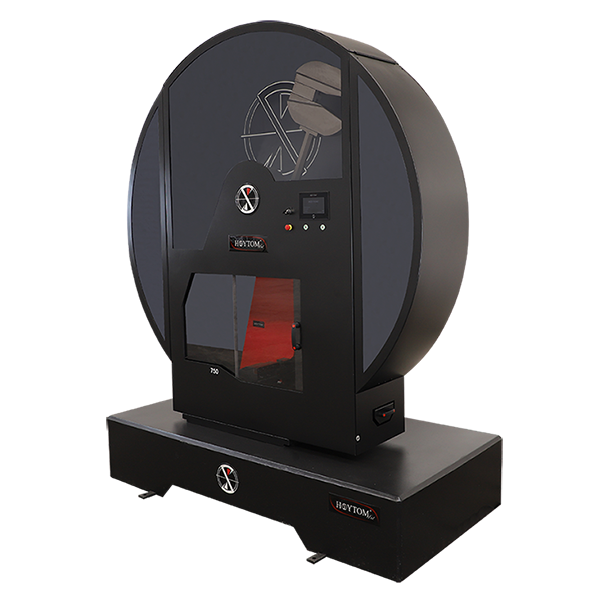
The Charpy impact test apparatus consists of a robust pendulum-based machine designed to deliver a precise, high-velocity strike to a notched specimen while minimizing energy losses. The primary components include the pendulum hammer, supporting frame, anvils and vise, measurement instruments, and safety features, all constructed to meet stringent standards for accuracy and reliability.[28][29] The pendulum hammer, the core striking element, features a weighted arm typically capable of delivering initial energies ranging from 20 J to 300 J for standard metallic testing, though higher capacities up to 750 J are available for specialized applications. The hammer incorporates a striker tip, often made of durable tungsten carbide for resistance to wear, with a standard radius of 2 mm (or 8 mm for certain configurations) to ensure consistent contact with the specimen. The pendulum is mounted on low-friction bearings to allow free swinging from an elevated release angle, usually around 140–150 degrees, achieving an impact velocity of approximately 5 m/s.[30][31][32] The machine frame provides a rigid, stable base to support the pendulum's oscillation and align the specimen horizontally, with the axis of rotation maintained parallel to a reference plane within tolerances of 2/1,000 to prevent misalignment-induced errors. Fixed anvils, spaced 40 mm apart (with a maximum deviation of 0.20 mm per ISO 148-2), form the supports beneath the specimen, ensuring the notch is centered and symmetrical within 0.5 mm of the mid-plane. A vise or clamp, either manual or pneumatic, secures the specimen ends against the anvils without introducing additional stress, using adjustable jaws to accommodate standard dimensions while avoiding deformation.[33][34][30] Energy absorption is quantified using measurement tools such as a dial gauge, optical encoder, or digital display that records the difference in pendulum height before and after impact, calibrated to joules with a resolution of 0.5–1 J depending on capacity. Safety enclosures, typically transparent shields or interlocked guards, surround the test area to contain flying fragments and protect operators from high-speed debris.[29][30] Calibration verifies the machine's integrity per ISO 148-2, including direct checks for dimensional accuracy (e.g., striker alignment via carbon paper imprint and anvil spacing) and dynamic tests for friction losses, which must not exceed 0.5–1% of nominal energy to ensure absorbed energy readings are within ±2 J or 1% accuracy. Pendulum friction, air resistance, and bearing play (limited to ≤0.25 mm) are quantified using reference pendulums or instrumented strikers, with periodic indirect verification via certified reference specimens.[33][3][28]Step-by-Step Testing Process
The Charpy impact test procedure begins with preparation of the test specimen, which must be conditioned to the specified test temperature to simulate real-world service conditions. For standard room-temperature testing, the specimen is used as prepared, but for low-temperature evaluations, it is immersed in a controlled environment such as a liquid bath or cooling chamber; for cryogenic testing at -196°C, liquid nitrogen is used to cool the specimen for a minimum of 5 to 10 minutes to achieve uniform temperature throughout, ensuring the temperature is maintained within ±1°C during transfer to the test apparatus. The conditioned specimen is then quickly transferred to the testing position using insulated tongs to minimize thermal recovery, typically within 5 seconds. In the setup phase, the notched specimen is securely positioned horizontally between the anvils of the test machine's vise, with the notch facing the approaching pendulum striker and centered precisely so the impact point aligns with the notch's midpoint, ensuring the longitudinal axis of the specimen is perpendicular to the pendulum's swing path. The pendulum is then raised and latched at a release angle of approximately 150° from the vertical position to achieve the required striking potential energy. The machine's safety interlocks are engaged to prevent premature release. Execution of the test involves releasing the pendulum latch, allowing it to swing freely under gravity and strike the opposite side of the notch at a velocity of about 5 m/s, fracturing the specimen in a three-point bending configuration. The pendulum continues unimpeded through the fracture plane to its maximum free swing height on the opposite side, with the entire motion captured to determine energy absorption. Following the impact, the absorbed energy is recorded directly from the machine's scale or digital readout, which measures the difference between the initial potential energy and the residual energy after fracture, expressed in joules. The broken specimen halves are removed and visually inspected for fracture surface features, such as cleavage or fibrous appearance, to note any qualitative aspects of failure mode. For reliable results, the test is repeated on at least three identical specimens under identical conditions to account for variability and compute meaningful averages. Safety protocols are integral throughout the process to protect operators from hazards associated with high-energy swings and extreme temperatures. Personnel must wear protective equipment, including impact-resistant shields, safety glasses, gloves, and insulated handling tools for cryogenic specimens, while ensuring the pendulum is fully latched and the machine is locked during loading and unloading to prevent accidental strikes. Ventilation is maintained in areas involving liquid nitrogen to avoid asphyxiation risks from nitrogen displacement.Specimen Requirements
Standard Dimensions and Preparation
The standard Charpy impact test specimen, as specified in ISO 148-1, is a rectangular bar measuring 55 mm in length with a square cross-section of 10 mm by 10 mm. A V-shaped notch is machined into the center of the specimen's length, perpendicular to the longitudinal axis, with a depth of 2 mm, an included angle of 45°, and a root radius of 0.25 mm. These dimensions ensure consistent stress concentration at the notch root, facilitating reproducible measurement of impact energy absorption.[35] Specimens are prepared by machining from bulk material to achieve the required geometry, typically using milling or grinding to form the notch after rough cutting the bar.[36] For heat-treated materials, final machining occurs after the heat treatment process to replicate service conditions, unless pre-heat-treatment machining is demonstrated to yield equivalent results.[37] Surface finish must be free of defects such as decarburization, which can alter material properties; for steels, etching or metallographic examination may be used to verify surface integrity. For wrought materials like rolled plates or forgings, specimen orientation is critical and follows ISO 3785, distinguishing longitudinal (L) testing—where the notch is perpendicular to the rolling direction—and transverse (T) testing—where the notch is parallel to the rolling direction—to account for anisotropic behavior. Specimens are marked on the face opposite the notch for identification, including orientation indicators (e.g., "L" or "T") and test details, ensuring traceability during handling.[37] Quality control includes dimensional verification with tolerances as outlined in ISO 148-1 to maintain test validity. The table below summarizes key dimensions and tolerances for the standard V-notch specimen:| Dimension | Nominal Value | Tolerance |
|---|---|---|
| Length | 55 mm | ±0.5 mm |
| Width | 10 mm | ±0.1 mm |
| Thickness | 10 mm | ±0.1 mm |
| Notch depth | 2 mm | ±0.05 mm |
| Notch angle | 45° | ±1° |
| Notch root radius | 0.25 mm | ±0.02 mm |
| Distance from notch to end | 27.5 mm | ±0.25 mm |