
Community hub
Recent from talks
Contribute something
Nothing was collected or created yet.
Reduction drive
View on Wikipedia
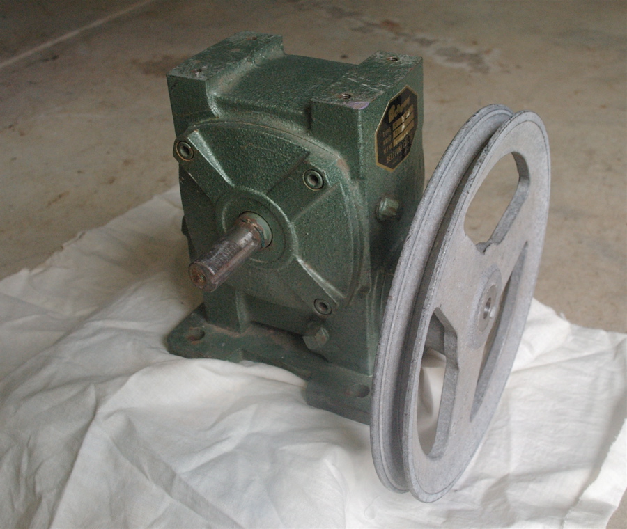
A reduction drive is a mechanical device to shift rotational speed. A planetary reduction drive is a small scale version using ball bearings in an epicyclic arrangement instead of toothed gears.
Reduction drives are used in engines of all kinds to increase the amount of torque per revolution of a shaft: the gearbox of any car is a ubiquitous example of a reduction drive. Common household uses are washing machines, food blenders and window-winders. Reduction drives are also used to decrease the rotational speed of an input shaft to an appropriate output speed. Reduction drives can be a gear train design or belt driven.
Planetary reduction drives are typically attached between the shaft of the variable capacitor and the tuning knob of any radio, to allow fine adjustments of the tuning capacitor with smooth movements of the knob. Planetary drives are used in this situation to avoid "backlash", which makes tuning easier. If the capacitor drive has backlash, when one attempts to tune in a station, the tuning knob will feel sloppy and it will be hard to perform small adjustments. Gear-drives can be made to have no backlash by using split gears and spring tension but the shaft bearings have to be very precise.
Application
[edit]Reduction gear in light aircraft
[edit]
Piston-engined light aircraft may have direct-drive to the propeller or may use a reduction drive. The advantages of direct-drive are simplicity, lightness and reliability, but a direct-drive engine may never achieve full output, as the propeller might exceed its maximum permissible rpm. For instance, a direct-drive aero engine (such as the Jabiru 2200) has a nominal maximum output of 64 kW (85 bhp) at 3,300 RPM,[1] but if the propeller cannot exceed 2,600 rpm, the maximum output would be only about 70 bhp. By contrast, a Rotax 912 has an engine capacity of only 56% of the Jabiru 2200, but its reduction gear (of 1 : 2.273 or 1 : 2.43) allows the full output of 80 bhp to be exploited. The Midwest twin-rotor wankel engine has an eccentric shaft that spins up to 7,800 rpm, so a 2.96:1 reduction gear is used.
Aero-engine reduction gears are typically of the gear type, but smaller two-stroke engines such as the Rotax 582 use belt drive with toothed belts, which is a cheap and lightweight option with built-in damping of power surges.
Reduction Drives on Marine Vessels
[edit]Most of the world's ships are powered by diesel engines which can be split into three categories, low speed (<400 rpm), medium speed (400-1200 rpm), and high speed (1200+ rpm). Low speed diesels operate at speeds within the optimum range for propeller usage. Thus it is acceptable to directly transmit power from the engine to the propeller. For medium and high speed diesels, the rotational speed of the crankshaft within the engine must be reduced in order to reach the optimum speed for use by a propeller.
Reduction drives operate by making the engine turn a high speed pinion against a gear, turning the high rotational speed from the engine to lower rotational speed for the propeller. The amount of reduction is based on the number of teeth on each gear. For example, a pinion with 25 teeth, turning a gear with 100 teeth, must turn 4 times in order for the larger gear to turn once. This reduces the speed by a factor of 4 while raising the torque 4 fold. This reduction factor changes depending on the needs and operating speeds of the machinery. The reduction gear aboard the Training Ship Golden Bear has a ratio of 3.6714:1. So when the two Enterprise R5 V-16 diesel engines operate at their standard 514 rpm, the propeller turns at 140 rpm.
A large variety of reduction gear arrangements are used in the industry. The three arrangements most commonly used are: double reduction utilizing two pinion nested, double reduction utilizing two-pinion articulated, and double reduction utilizing two-pinion locked train.[2]
The gears used in a ship's reduction gearbox are usually double helical gears.[2] This design helps lower the amount of required maintenance and increase the lifetime of the gears. Helical gears are used because the load upon it is more distributed than in other types. The double helical gear set can also be called a herringbone gear and consists of two oppositely angled sets of teeth. A single set of helical teeth will produce a thrust parallel to the axle of the gear (known as axial thrust) due to the angular nature of the teeth. By adding a second set opposed to the first set, the axial thrust created by both sets cancels each other out.[3]
When installing reduction gears on ships the alignment of the gear is critical. Correct alignment helps ensure a uniform distribution of load upon each pinion and gear. When manufactured, the gears are assembled in such a way as to obtain uniform load distribution and tooth contact. After completion of construction and delivery to shipyard it is required that these gears achieve proper alignment when first operated under load. Some shipbuilders will have the gears transported and installed as a complete assembly. Others will have the gears dismantled, shipped, reassembled in their shops and lowered as a complete assembly into the ship. While finally others will have the gears dismantled, shipped and reassembled in the ship. These three methods are the most common used by shipbuilders to achieve proper alignment and each of them work based upon the assumption that proper alignment was correctly achieved at the manufacturer.[2]
Because of the involvement in the process of aligning reduction drives, there are two main sources of responsibility to achieve proper alignment. That of the shipbuilder and that of the gear manufacturer. The shipbuilder must provide a foundation that is sufficiently strong and rigid so that the gear mounting surface does not deflect greatly under operating conditions, a shaft alignment drawing that details the positions of line bearing and the method for aligning the forward piece of line shafting to the reduction gear coupling and the location of stern tube being such that the normal wear down of the stern tube will not induce significant movement of the reduction gear coupling from its proper alignment.
The gear manufacturer is then responsible for ensuring basic gear alignment, such that the final assembly measurements are taken carefully and recorded for the reduction drive to be installed correctly, proper tooth contact in the factory, where the manufacturer accurately and precisely assembles the gears and pinions, and denoting all steps performed, making measurements of parts at the different steps and final assembly then forwarding this data to the shipbuilder so that they may assure the degree of accuracy required by the gear designer in the resulting shipboard assembly.[2]
Thrust bearings do not commonly appear on reduction drives on ships because axial loading is handled by a thrust bearing separate from the reduction drive assembly. But on smaller reduction drives attached to auxiliary machinery or if the design of the ship demands it, one can find thrust bearings as a part of the assembly.[4]
In order to ensure a reduction drive's smooth working and long lifetime, it is vital to have lubricating oil. A reduction drive that is run with oil free of impurities like water, dirt, grit and flakes of metal, requires little care in comparison to other type of engine room machinery. In order to ensure that the lube oil in the reduction gears stay this way a lube oil purifier will be installed with the drive.[4]
Types
[edit]Types of reduction drives include cycloidal, strain wave gear, and worm gear drives.
References
[edit]- ^ "4 cylinder". www.jabiru.net.au. Archived from the original on 2012-01-15.
- ^ a b c d Guide to propulsion reduction gear alignment and installation (Technical and research bulletin (Society of Naval Architects and Marine Engineers (U.S.)); 3-10). New York: Society of Naval Architects and Marine Engineers. 1961.
- ^ Marine propulsion equipment: Section I: Table of contents, principal characteristics and special data. Sunnyvale, CA: Joshua Hendy Iron Works. 1944.
- ^ a b Machinist's Mate 3 & 2 (Surface). Naval Education and Training Professional Development and Technology Center. 2004.
Reduction drive
View on GrokipediaDefinition and Purpose
Definition
A reduction drive is a mechanical power transmission device that decreases the rotational speed of an input shaft, typically driven by a motor or engine, while simultaneously increasing the output torque, achieved through gear trains or other mechanisms employing a gear ratio greater than 1:1.[2] This configuration ensures that the output rotational speed is lower than the input, enabling efficient adaptation of high-speed power sources to applications requiring greater force at reduced velocities.[4] The concept of reduction drives dates back to ancient times, with early gear mechanisms documented as far back as the 12th century by Ismail al-Jazari, though they saw significant development and widespread application during the Industrial Revolution in the 19th century, evolving from simple gear pairs to complex multi-stage systems.[5] The primary components of a reduction drive include an input shaft connected to the power source, a reduction mechanism such as interlocking gears to achieve the speed-torque trade-off, an output shaft delivering the modified rotation, and an enclosing housing that supports and aligns these elements while containing lubricants.[2] Unlike speed increaser drives, which amplify rotational speed at the expense of torque using gear ratios less than 1:1, reduction drives specifically produce slower output speeds to prioritize torque multiplication.[6]Purpose and Benefits
The primary purpose of a reduction drive is to convert the high-speed, low-torque output of a motor or engine into a low-speed, high-torque output suitable for the requirements of driven loads, thereby enabling efficient power transmission in mechanical systems.[7][8] This matching is achieved through gear ratios that reduce rotational speed while multiplying torque, allowing machinery to operate optimally without overloading the prime mover.[7] Key benefits include significantly increased torque for handling heavy loads, which supports applications requiring substantial force without necessitating larger motors.[8] Reduced operating speeds also minimize wear on components, extending equipment lifespan and lowering maintenance needs through designs that incorporate anti-backlash mechanisms to maintain precise contact.[7] Additionally, reduction drives enable compact designs that fit space-constrained environments and promote energy efficiency by optimizing speed matching, which reduces power losses and overall consumption.[8] Economically and operationally, these drives lower costs by prolonging equipment durability and decreasing energy use, as torque multiplication occurs without additional power input from the source.[7] In contrast to direct drive systems, which provide no torque amplification and can lead to inefficiencies or overloads in high-load scenarios due to mismatched speeds, reduction drives enhance reliability and performance across diverse machinery.[7][9]Principles of Operation
Gear Ratio Fundamentals
A gear ratio in a reduction drive is defined as the ratio of the number of teeth on the driven gear to the number of teeth on the driving gear, expressed as , which results in the output shaft rotating slower than the input shaft.[10] This ratio determines the extent of speed reduction, as the driven gear completes fewer revolutions for each full rotation of the driving gear (pinion). For instance, if the driving gear has 20 teeth and the driven gear has 60 teeth, the gear ratio is 3:1, meaning the output speed is one-third of the input speed.[11] The fundamental principle relies on the meshing of gear teeth, where the linear velocity at the pitch circle is equal for both gears, ensuring smooth power transmission without slippage.[12] The gear ratio can also be calculated kinematically as , where denotes angular velocity, directly linking the teeth ratio to rotational speeds since .[11] In practice, when gears mesh externally, the driving and driven gears rotate in opposite directions due to the interlocking teeth pushing against each other.[13] For multi-stage reductions, the overall gear ratio is the product of individual stage ratios; for example, two stages with ratios of 2:1 and 3:1 yield a compound ratio of 6:1, allowing greater reductions without excessively large gears in a single stage.[10][12] Implementation of gear ratios often involves single-stage setups for moderate reductions, where one pair of meshing gears achieves the desired ratio, or multi-stage configurations for higher reductions by cascading multiple pairs.[14] Idler gears, placed between the driving and driven gears, transmit motion without altering the overall ratio, as the effective ratio depends only on the first and last gears' teeth counts; however, each idler reverses the rotational direction.[10] In a gear train, an odd number of meshing stages (external meshes) results in the output rotating opposite to the input, while an even number maintains the same direction, a consequence of successive direction reversals at each mesh.[15][13]Torque-Speed Relationship
In reduction drives, the torque and speed at the output are directly related to the input through the gear ratio (GR), which is defined as the ratio of the number of teeth on the driven gear to the driving gear. The output torque is multiplied by the GR, while the output speed is divided by the GR, establishing an inverse relationship between torque and speed. Specifically, the output torque is given by , where is the input torque and is the efficiency of the gear system (with ). The output speed is , where is the input angular speed.[16][17] This relationship stems from the conservation of mechanical power in ideal conditions, where input power approximates output power: , with power defined as . In practice, losses due to friction, churning, and other factors reduce efficiency, so , meaning the actual output torque is less than the ideal multiplication by GR.[16][17] The implications of this torque-speed relationship are central to reduction drive design: a higher GR provides greater torque multiplication at the expense of reduced output speed, allowing high-speed, low-torque inputs (such as from electric motors) to drive high-torque, low-speed loads. Selection of GR depends on specific load requirements, balancing the need for torque amplification against acceptable speed reduction to maintain operational efficiency.[10][14] Consider a two-stage reduction system achieving an overall GR of 4:1, with each stage having a 2:1 ratio (assuming ideal conditions for derivation, per stage). Start with input torque and speed . After the first stage, torque doubles to (multiplied by 2) and speed halves to (divided by 2). Entering the second stage, the intermediate torque is then doubled again to , while the intermediate speed is halved to . Thus, the overall effect compounds the multiplication: torque is doubled twice for a net factor of 4, and speed is halved twice for a net division by 4, yielding the 4:1 GR. In real systems, efficiency per stage would adjust the final torque to .[14][10]Types
Gear-Based Reduction Drives
Gear-based reduction drives utilize toothed wheels to achieve speed reduction and torque multiplication between shafts, primarily through configurations that maintain precise meshing for efficient power transmission. These systems are fundamental in mechanical engineering for applications requiring high torque at lower speeds, such as in industrial machinery and vehicle transmissions. The primary configurations include spur, helical, bevel/hypoid, worm, planetary, and harmonic (strain wave) gears, each suited to specific shaft orientations and operational demands.[18][19] Spur gears feature straight teeth parallel to the axis of rotation and are designed for parallel shafts, enabling simple and cost-effective power transfer. Their involute tooth profile ensures conjugate action for smooth meshing, with efficiencies reaching 97-99.5% in well-lubricated systems. However, at high speeds, the abrupt tooth engagement generates significant noise and vibration, limiting their use in precision or quiet environments. Spur gears are favored for heavy-load applications due to their robustness and minimal backlash when precisely manufactured.[18][9] Helical gears incorporate teeth cut at an angle to the shaft axis, also for parallel shafts, which allows multiple teeth to contact simultaneously for smoother operation and higher load capacity compared to spur gears. This helical arrangement supports pitch-line velocities up to 50 m/s and maintains high efficiency (97-99.5%), making them suitable for high-speed reduction drives. A key trade-off is the generation of axial thrust proportional to the helix angle, necessitating thrust bearings to manage the separating forces on the shafts. Double-helical (herringbone) designs mitigate this thrust by opposing helix directions.[18][20] Bevel and hypoid gears accommodate perpendicular shaft arrangements, essential for orthogonal power transmission in systems like vehicle differentials. Bevel gears have conical pitch surfaces with straight or spiral teeth, typically at 90-degree angles, supporting velocities up to 50 m/s for spiral variants and efficiencies of 97-99.5%; they provide strong torque handling but require paired manufacturing for accuracy. Hypoid gears extend this capability with offset, non-intersecting axes on hyperboloid surfaces, enabling compact designs with reduction ratios up to 200:1 in multi-stage configurations and smoother meshing, though at slightly lower efficiencies (80-95%) due to sliding contact, which demands specialized lubrication. These are prevalent in automotive rear axles for their ability to lower drive shafts while distributing torque effectively.[18][21][22] Worm gears consist of a screw-like worm meshing with a worm wheel for perpendicular, non-intersecting shafts, offering high reduction ratios from 5:1 to 100:1 or more in a single stage with self-locking capability to prevent backdriving. They achieve efficiencies of 50-90%, lower due to sliding friction, requiring lubrication, and are compact for high-torque, low-speed applications like elevators and tuning mechanisms, though limited at high speeds due to heat generation.[23][24] Planetary gear systems feature a central sun gear, orbiting planet gears, and an outer ring gear in coaxial arrangement, providing high reduction ratios up to 10:1 per stage (or higher in multi-stage) with excellent torque density and efficiencies of 95-98%. Their compact design distributes load across multiple planets for smooth operation and high power handling, ideal for automotive transmissions and robotics, though complex manufacturing increases cost.[25] Harmonic drives, based on strain wave gearing, achieve high reduction ratios in a compact form using a wave generator that deforms a flexible spline against a rigid circular spline. The elliptical wave generator creates a traveling strain wave in the flexspline, engaging teeth progressively to produce ratios from 50:1 to 160:1 in a single stage without backlash, as the continuous deformation eliminates play. This design enables precise positioning in space-constrained setups, with torsional stiffness high enough for robotic joints. Advantages include zero backlash and high reduction density, but disadvantages encompass lower efficiency around 70-80% due to flexing losses, increased moment of inertia from the wave generator, and higher manufacturing costs from specialized materials like high-elasticity alloys.[26][27][28] Key features of gear-based reduction drives include techniques to minimize backlash—the clearance between meshing teeth that can cause positioning errors—and strategies for even load distribution in multi-gear trains. Backlash is reduced by precision grinding, slightly thinning gear teeth during cutting, or using preload mechanisms like spring-loaded split gears to maintain constant mesh contact. In multi-gear trains, load distribution is optimized through factors such as face width, helix angles, and alignment to prevent uneven stress, with analytical models accounting for these to enhance durability and efficiency. Historically, spur gears dominated reduction drives since the 1800s, powering early industrial machinery with their straightforward design amid the rise of steam engines and factories. Helical gears gained prominence in the early 20th century, particularly in automotive and aviation applications, to achieve quieter operation and reduced vibration over spur gears at elevated speeds.[18][30]Non-Gear Reduction Drives
Non-gear reduction drives achieve speed reduction and torque multiplication through mechanisms that avoid direct meshed gear contact, relying instead on flexible, hydrodynamic, or strain-based transmission methods. These systems are particularly useful in applications requiring misalignment tolerance, smooth operation, or compact high-ratio designs, though they often trade some efficiency or precision for these benefits.[31] Belt drives utilize pulleys connected by V-belts, flat belts, or timing belts to transmit power, with speed reduction determined by the ratio of pulley diameters. V-belts and timing belts offer advantages such as tolerance for shaft misalignment up to several degrees and quieter operation compared to rigid systems, making them suitable for moderate-load environments. Timing belts, in particular, provide near-constant velocity ratios with efficiencies up to 98% and eliminate slippage under normal conditions, though they require precise initial tensioning. However, belts risk slipping under high torque loads exceeding 10-20% of their rated capacity, and they exhibit lower transmission accuracy for precision tasks due to potential elongation over time.[32][33][34] Chain drives employ roller chains engaging sprockets to transfer power, achieving reduction ratios similar to belts but with greater load-handling capacity for heavy-duty applications. Roller chains can transmit torques several times higher than equivalent belts without slippage, maintaining efficiencies around 95-98%, and they perform well across a range of speeds, including low-speed starts and stops. Their robust design allows center distances up to 3 meters or more in some configurations. Drawbacks include the need for regular lubrication to prevent wear, potential vibration and noise at high speeds above 1000 rpm, and sensitivity to misalignment, which can accelerate chain fatigue.[35][36][37] Fluid couplings and torque converters operate on hydrodynamic principles, using viscous fluids within sealed housings to couple input and output shafts without mechanical contact. In a basic fluid coupling, impeller-driven fluid flow transfers torque to a turbine, providing smooth acceleration and overload protection by slipping at peak loads. Torque converters extend this by incorporating a stator to redirect fluid flow, multiplying input torque by factors up to 2.5 during startup for enhanced low-speed performance. These devices excel in variable-speed scenarios, absorbing shocks and vibrations to reduce drivetrain wear, with no backlash due to the fluid medium. Efficiencies typically range from 90-95% at full speed but drop to 80% or lower during slip, and they consume more energy than direct mechanical links due to inherent fluid drag.[38][39][40] In comparison, belt drives suit low-precision needs with their simplicity and quietness, chain drives handle medium loads reliably where lubrication is feasible, and fluid systems provide variable-speed smoothness for dynamic loads, each selected based on trade-offs in efficiency, maintenance, and environmental fit.[31][36][38]Applications
Aviation and Automotive
In aviation, particularly for light aircraft, propeller speed reduction units (PSRUs) are employed to adapt high engine rotational speeds to the lower optimal speeds required for efficient propeller operation. For instance, in experimental light aircraft using converted automotive engines that operate at 5000–6000 RPM, PSRUs typically provide reduction ratios between 2:1 and 3:1 to drive the propeller at 2400–2700 RPM, enhancing aerodynamic efficiency by preventing excessive tip speeds that could lead to transonic drag.[41][42] These units often utilize helical or planetary gear configurations to achieve smooth torque multiplication, allowing the engine to run at its peak power band while the propeller maintains effective thrust generation.[43] The adoption of reduction gearing in aircraft began in earnest during the 1920s with the development of larger radial engines, such as the Bristol Jupiter VIIIF, which incorporated gearing to decouple engine crankshaft speeds from propeller rotation for improved performance in heavier airframes.[44][45] Although the Wright brothers identified the need for such gearing as early as 1903, practical implementation in production engines like those from Wright Aeronautical emerged later in the decade to handle increasing power outputs without oversized propellers.[44] In modern contexts, PSRUs remain critical for propeller-driven light aircraft, where they enable the use of compact, high-RPM engines while optimizing propulsion torque for climb and cruise.[41] A primary challenge in aviation PSRU design is minimizing weight to preserve aircraft performance and payload capacity, as added mass from gears and housings can increase fuel consumption and reduce range.[46] Engineers address this through lightweight materials and compact layouts, though reliability under vibrational loads remains a concern in certified applications.[47] In automotive applications, reduction drives are integral to transmissions and differentials, where they convert the engine's moderate RPM and torque into the high torque needed at the wheels for acceleration and load handling. Multi-speed manual or automatic transmissions employ gear sets with ratios often ranging from 3:1 in lower gears to 0.7:1 in overdrive, allowing the engine to operate efficiently across varying speeds.[1] Differentials provide a final reduction stage, typically 3:1 to 5:1, while permitting differential wheel speeds during turns, essential for vehicle stability on roads.[19] Continuously variable transmissions (CVTs) offer seamless ratio adjustments from about 0.4:1 to 3.5:1 using belts or chains, maintaining engine RPM near peak efficiency for better fuel economy in passenger cars.[48] In electric vehicles (EVs), single-speed reduction gearboxes are standard, reducing high motor speeds (up to 10,000–20,000 RPM) to wheel speeds via ratios around 8:1 to 10:1, optimizing torque delivery without multi-gear complexity.[49] This setup leverages the motor's broad torque curve, providing instant acceleration while simplifying the drivetrain. Heat dissipation poses a significant challenge in automotive reduction drives, particularly under high-load conditions like towing or rapid acceleration, where friction in gears and lubricants can exceed 100°C, risking component wear and efficiency loss.[50] Advanced cooling systems, such as oil jets or integrated radiators, are employed to manage these thermal stresses in both internal combustion and EV applications.[51]Marine and Industrial
In marine applications, reduction drives play a critical role in adapting the output speeds of diesel engines or steam and gas turbines to the optimal rotational speeds for propeller shafts, enabling efficient propulsion in large vessels. These gearboxes typically employ multi-stage configurations, such as double or triple reductions, to achieve overall ratios ranging from 5:1 to 20:1 or higher, depending on the power source—for instance, reducing turbine speeds of several thousand RPM to propeller speeds around 80-120 RPM for enhanced thrust and hydrodynamic efficiency.[52] Reversible reduction drives, incorporating clutches or epicyclic gears, allow seamless direction changes without reversing the engine, which is essential for precise maneuvering during docking, undocking, or navigation in confined waters.[53][54] The International Maritime Organization's (IMO) Energy Efficiency Design Index (EEDI), introduced under MARPOL Annex VI, mandates minimum energy efficiency standards for new ships based on CO2 emissions per transport work, directly influencing the design of reduction gears to optimize propulsion systems and reduce fuel consumption by promoting lighter, more efficient materials and precise torque matching.[55] Following World War II, the adoption of advanced double helical reduction gears in commercial shipping fleets accelerated, building on wartime innovations to standardize smoother, higher-capacity systems that improved overall propulsion efficiency and supported the post-war economic boom in global trade.[52][56] In industrial environments, reduction drives are integral to heavy-duty operations, providing multi-stage torque multiplication for applications like conveyor belts in mining and manufacturing, overhead cranes in construction and ports, and rolling mills in steel production, where low-speed, high-torque output is required to handle substantial loads without excessive energy loss.[57] These systems often utilize helical or planetary gear arrangements in up to quadruple stages to achieve ratios exceeding 100:1, ensuring reliable power transmission in stationary setups.[58] Vibration isolation mounts, such as elastomeric pads or spring isolators, are routinely integrated to dampen operational harmonics and external disturbances, thereby reducing stress on gear teeth and bearings to prevent fatigue failures and extend service life in demanding conditions.[59][60]Household and Other Uses
In household appliances, reduction drives are essential for converting the high-speed output of electric motors into the lower speeds and higher torques required for effective operation. For instance, in top-loading washing machines, belt-driven systems connect the motor to the agitator and transmission pulley, where differing pulley diameters provide a mechanical advantage for speed reduction, enabling the agitator to generate sufficient torque for cleaning action while minimizing motor strain.[61] Similarly, planetary gear reductions are commonly integrated into food mixers and blenders to deliver high torque at reduced speeds, allowing for efficient blending or mixing of viscous materials without excessive motor power consumption.[62] Electric window openers in homes often employ worm gear reduction mechanisms paired with DC motors, which provide high torque multiplication and self-locking capabilities to hold windows securely in position without additional braking, ensuring safe and reliable automation.[63] These designs prioritize compactness and low noise, making them suitable for residential environments, and they seamlessly integrate with small electric motors to enhance user convenience in everyday tasks.[64] Beyond household items, reduction drives play a critical role in robotics for precise motion control, where harmonic or cycloidal gear systems reduce motor speeds to achieve fine positional accuracy and high torque in joint actuators, enabling tasks like manipulation in industrial and service robots.[65] In the 2020s, the proliferation of smart home devices has driven the adoption of micro-reduction drives, such as miniature planetary or worm gear units in robotic vacuum cleaners and automated blinds, which offer quiet, energy-efficient operation and responsive control via integrated sensors.[66] This trend emphasizes affordable, low-maintenance designs that support automation while matching motor speeds to application needs for optimal performance.[67]Design Considerations
Efficiency and Materials
The efficiency of a reduction drive quantifies the ratio of output power to input power, typically expressed as a percentage using the formula , where losses primarily arise from friction in gear meshes and lubrication churning.[68] These friction losses in gear systems contribute significantly to power dissipation, depending on the number of stages and operating conditions, while also generating heat that can further degrade performance if not managed.[69] Proper lubrication mitigates these issues; common types include mineral oils for standard applications, greases for sealed low-speed setups, and synthetic oils (such as polyalphaolefins or esters) that reduce viscous drag and friction coefficients, enabling overall efficiencies of 90-98% in well-designed systems.[70][71] For instance, helical gears in reduction drives often achieve around 95% efficiency per stage due to smoother tooth engagement compared to spur gears.[20] Material selection in reduction drives balances strength, weight, durability, and environmental resistance to optimize efficiency and longevity. Alloy steels, such as carburized AISI 8620 or nitrided 18-4, form the backbone for high-load gears due to their superior hardness and fatigue resistance after heat treatment.[72] For lightweight applications, engineering composites like carbon-fiber-reinforced polymers are increasingly used to minimize inertia and energy losses in rotational systems.[73] Wear-resistant coatings, including nitriding processes that diffuse nitrogen into steel surfaces, enhance gear life by reducing frictional wear and improving load-bearing capacity without adding significant mass.[72] Criteria for material choice emphasize operational demands; high-strength alloys like nickel-aluminum bronzes are preferred for marine environments to withstand corrosion from saltwater exposure while maintaining structural integrity.[74] In contrast, plastics such as polyacetal (POM) or nylon suit low-load household applications, offering self-lubrication, noise reduction, and cost-effectiveness without compromising efficiency in non-demanding torque scenarios.[75] Design often adheres to standards such as AGMA 2000-A88 for gear accuracy and performance evaluation.[76]Maintenance and Limitations
Proper maintenance of reduction drives is crucial to ensure longevity, efficiency, and safety, particularly in gear-based systems where friction and wear are primary concerns. Regular lubrication forms the cornerstone of maintenance routines, with oil levels checked monthly and full changes recommended every three months or as specified by the manufacturer, using lubricants suited to the operating environment to minimize wear on gears and bearings.[77] Initial break-in periods often require oil replacement after 24 hours for worm gear configurations or 100 hours for shaft-mounted reducers to remove contaminants from new components.[78] Visual inspections should be conducted quarterly to detect signs of leakage, misalignment, or surface damage, while temperature monitoring via sensors helps identify overheating that could indicate lubrication failure or overload.[79] Advanced practices include condition-based monitoring, such as vibration analysis with sampling rates of 2 kHz or higher and oil debris sensors, which enable early detection of faults like bearing wear or gear pitting, reducing unplanned downtime by up to 70% in industrial applications.[80] Seals and bearings require periodic checks for integrity, with replacements every 1-2 years depending on load, and alignment verification using laser tools to prevent uneven wear. For non-gear reduction drives, such as belt systems, maintenance emphasizes tension adjustments every three to six months and inspections for cracking or slippage, alongside environmental cleaning to avoid debris accumulation.[81] Overall, adherence to manufacturer guidelines and run-in procedures—such as operating at varying torque levels (25-100%) with filtered oil—can extend service life by stabilizing wear particles and maintaining oil cleanliness to ISO 18/16/13 standards.[80] Despite their utility, reduction drives have inherent limitations that impact performance and applicability. Gear-based systems suffer from efficiency losses due to friction and sliding contact, with worm gears generally lower in efficiency than spur gears at 98%, leading to heat generation and reduced output torque in prolonged high-load operations.[82][83] Noise and vibration are significant drawbacks, especially in spur gear configurations where abrupt tooth engagement produces high decibel levels unsuitable for quiet environments, while helical gears mitigate this but introduce axial thrust requiring additional bearings.[82] Manufacturing precision demands increase costs, as complex geometries in bevel or planetary types necessitate specialized tooling and skilled labor.[84] Backlash—unavoidable play between meshing teeth—limits precision in applications requiring exact positioning, such as robotics, and accumulates over time due to wear, necessitating frequent adjustments. High reduction ratios often result in larger, heavier units, constraining use in compact or weight-sensitive designs like aviation, and all gear systems demand ongoing lubrication to avoid seizure, unlike some non-gear options. Torque spikes from mismatched controls can accelerate failure, with field data showing peaks up to 665 kNm causing edge loading on bearings.[80] Non-gear drives, such as belts, avoid backlash but introduce slippage under high torque and require more frequent tensioning, limiting them to lower-power scenarios.[80] These constraints underscore the need for application-specific selection to balance torque multiplication against efficiency and maintenance demands.References
- https://ntrs.[nasa](/page/NASA).gov/api/citations/19860005142/downloads/19860005142.pdf