

Community hub
Recent from talks
Contribute something
Nothing was collected or created yet.

A gear[1][2] or gearwheel,[3][4][5] also called a toothed wheel, is a rotating machine part typically used to transmit rotational motion or torque by means of a series of "teeth" that engage with compatible teeth of another gear or other part. The teeth can be integral saliences or cavities machined on the part, or separate pegs inserted into it. In the latter case, the gear is usually called a cogwheel. A cog may be one of those pegs[6][7][8] or the whole gear.[9][6][8] Two or more meshing gears are called a gear train.
The smaller member of a pair of meshing gears is often called pinion. Most commonly, gears and gear trains can be used to trade torque for rotational speed between two axles or other rotating parts or to change the axis of rotation or to invert the sense of rotation. A gear may also be used to transmit linear force or linear motion to a rack, a straight bar with a row of compatible teeth.

Gears are among the most common mechanical parts. They come in a great variety of shapes and materials, and are used for many different functions and applications. Diameters may range from a few μm in micromachines,[10] to a few mm in watches and toys to over 10 metres in some mining equipment.[11] Other types of parts that are somewhat similar in shape and function to gears include the sprocket, which is meant to engage with a link chain instead of another gear, and the timing pulley, meant to engage a timing belt. Most gears are round and have equal teeth, designed to operate as smoothly as possible; but there are several applications for non-circular gears, and the Geneva drive has an extremely uneven operation, by design.
Gears can be seen as instances of the basic lever "machine".[12] When a small gear drives a larger one, the mechanical advantage of this ideal lever causes the torque T to increase but the rotational speed ω to decrease. The opposite effect is obtained when a large gear drives a small one. The changes are proportional to the gear ratio r, the ratio of the tooth counts: namely, T2/T1 = r = N2/N1, and ω2/ω1 = 1/r = N1/N2. Depending on the geometry of the pair, the sense of rotation may also be inverted (from clockwise to anti-clockwise, or vice versa).
Most vehicles have a transmission or "gearbox" containing a set of gears that can be meshed in multiple configurations. The gearbox lets the operator vary the torque that is applied to the wheels without changing the engine's speed. Gearboxes are used also in many other machines, such as lathes and conveyor belts. In all those cases, terms like "first gear", "high gear", and "reverse gear" refer to the overall torque ratios of different meshing configurations, rather than to specific physical gears. These terms may be applied even when the vehicle does not actually contain gears, as in a continuously variable transmission.[13]
History
[edit]The oldest functioning gears by far are not man made, but are seen in the hind legs of the nymphs of the planthopper insect Issus coleoptratus.
.jpg)
The earliest man-made gears that have not been lost or destroyed date to 4th century BC China[14] (Zhan Guo times – Late East Zhou dynasty), which have been preserved at the Luoyang Museum of Henan Province, China.
.webp)
In Europe, Aristotle mentions gears around 330 BC, as wheel drives in windlasses. He observed that the direction of rotation is reversed when one gear wheel drives another gear wheel. Philon of Byzantium was one of the first who used gears in water raising devices.[15] Gears appear in works connected to Hero of Alexandria, in Roman Egypt circa AD 50,[16] but can be traced back to the mechanics of the Library of Alexandria in 3rd-century BC Ptolemaic Egypt, and were greatly developed by the Greek polymath Archimedes (287–212 BC).[17] The earliest surviving gears in Europe were found in the Antikythera mechanism an example of a very early and intricate geared device, designed to calculate astronomical positions of the sun, moon, and planets, and predict eclipses. Its time of construction is now estimated between 150 and 100 BC.[18][19][20]
.jpg)
The Chinese engineer Ma Jun (c. 200–265) described a south-pointing chariot. A set of differential gears connected to the wheels and to a pointer on top of the chariot kept the direction of latter unchanged as the chariot turned.[21]
Another early surviving example of geared mechanism is a complex calendrical device showing the phase of the Moon, the day of the month and the places of the Sun and the Moon in the Zodiac was invented in the Byzantine empire in the early 6th century.[22][23]
Geared mechanical water clocks were built in China by 725.[citation needed]
Around 1221, a geared astrolabe was built in Isfahan showing the position of the moon in the zodiac and its phase, and the number of days since new moon.[24]
The worm gear was invented in the Indian subcontinent, for use in roller cotton gins, some time during the 13th–14th centuries.[25]
A complex astronomical clock, called the Astrarium, was built between 1348 and 1364 by Giovanni Dondi dell'Orologio. It had seven faces and 107 moving parts; it showed the positions of the sun, the moon and the five planets then known, as well as religious feast days.[26] The Salisbury Cathedral clock, built in 1386, it is the world's oldest still working geared mechanical clock.
Differential gears were used by the British clock maker Joseph Williamson in 1720.[citation needed]
Etymology
[edit]The word gear is probably from Old Norse gørvi (plural gørvar) 'apparel, gear,' related to gøra, gørva 'to make, construct, build; set in order, prepare,' a common verb in Old Norse, "used in a wide range of situations from writing a book to dressing meat". In this context, the meaning of 'toothed wheel in machinery' first attested 1520s; specific mechanical sense of 'parts by which a motor communicates motion' is from 1814; specifically of a vehicle (bicycle, automobile, etc.) by 1888.[27]
A cog is a tooth on a wheel. From Middle English cogge, from Old Norse (compare Norwegian kugg ('cog'), Swedish kugg, kugge ('cog, tooth')), from Proto-Germanic *kuggō (compare Dutch kogge ('cog boat'), German Kock), from Proto-Indo-European *gugā ('hump, ball') (compare Lithuanian gugà ('pommel, hump, hill'), from PIE *gēw- ('to bend, arch').[28] First used c. 1300 in the sense of 'a wheel having teeth or cogs; late 14c., 'tooth on a wheel'; cog-wheel, early 15c.[29]
Materials
[edit]
The gears of the Antikythera mechanism are made of bronze, and the earliest surviving Chinese gears are made of iron. These metals, as well as tin, have been generally used for clocks and similar mechanisms to this day.
Historically, large gears, such as those used in flour mills, were commonly made of wood rather than metal. They were cogwheels, made by inserting a series of wooden pegs or cogs around the rim of a wheel. The cogs were often made of maple wood.
Wooden gears have been gradually replaced by ones made or metal, such as cast iron at first, then steel and aluminum. Steel is most commonly used because of its high strength-to-weight ratio and low cost. Aluminum is not as strong as steel for the same geometry, but is lighter and easier to machine. Powder metallurgy may be used with alloys that cannot be easily cast or machined.

Still, because of cost or other considerations, some early metal gears had wooden cogs, each tooth forming a type of specialised 'through' mortise and tenon joint[30]
More recently engineering plastics and composite materials have been replacing metals in many applications, especially those with moderate speed and torque. They are not as strong as steel, but are cheaper, can be mass-manufactured by injection molding,[31] and do not need lubrication. Plastic gears can even be intentionally designed to be the weakest part in a mechanism, so that in case of jamming they will fail first and thus avoid damage to more expensive parts. Such "sacrificial" gears may be a simpler alternative to other overload-protection devices such as clutches and torque-limited or current-limited motors.

In spite of the advantages of metal and plastic, wood continued to be used for large gears until a couple of centuries ago, because of cost, weight, tradition, or other considerations. In 1967 the Thompson Manufacturing Company of Lancaster, New Hampshire still had a very active business in supplying tens of thousands of maple gear teeth per year, mostly for use in paper mills and grist mills, some dating back over 100 years.[32]
Manufacture
[edit]The most common techniques for gear manufacturing are dies, sand, and investment casting; injection molding; powder metallurgy; blanking; and gear cutting.
As of 2014, an estimated 80% of all gearing produced worldwide is produced by net shape molding. Molded gearing is usually powder metallurgy, plastic injection, or metal die casting.[33] Gears produced by powder metallurgy often require a sintering step after they are removed from the mold. Cast gears require gear cutting or other machining to shape the teeth to the necessary precision. The most common form of gear cutting is hobbing, but gear shaping, milling, and broaching may be used instead.
Metal gears intended for heavy duty operation, such as in the transmissions of cars and trucks, the teeth are heat treated to make them hard and more wear resistant while leaving the core soft but tough. For large gears that are prone to warp, a quench press is used.
Gears can be made by 3D printing; however, this alternative is typically used only for prototypes or very limited production quantities, because of its high cost, low accuracy, and relatively low strength of the resulting part.
Comparison with other drive mechanisms
[edit]Besides gear trains, other alternative methods of transmitting torque between non-coaxial parts include link chains driven by sprockets, friction drives, belts and pulleys, hydraulic couplings, and timing belts.
One major advantage of gears is that their rigid body and the snug interlocking of the teeth ensure precise tracking of the rotation across the gear train, limited only by backlash and other mechanical defects. For this reason they are favored in precision applications such as watches. Gear trains also can have fewer separate parts (only two) and have minimal power loss, minimal wear, and long life. Gears are also often the most efficient and compact way of transmitting torque between two non-parallel axes.
On the other hand, gears are more expensive to manufacture, may require periodic lubrication, and may have greater mass and rotational inertia than the equivalent pulleys. More importantly, the distance between the axes of matched gears is limited and cannot be changed once they are manufactured. There are also applications where slippage under overload or transients (as occurs with belts, hydraulics, and friction wheels) is not only acceptable but desirable.
Ideal gear model
[edit]For basic analysis purposes, each gear can be idealized as a perfectly rigid body that, in normal operation, turns around a rotation axis that is fixed in space, without sliding along it. Thus, each point of the gear can move only along a circle that is perpendicular to its axis and centered on it. At any moment t, all points of the gear will be rotating around that axis with the same angular speed ω(t), in the same sense. The speed need not be constant over time.
The action surface of the gear consists of all points of its surface that, in normal operation, may contact the matching gear with positive pressure. All other parts of the surface are irrelevant (except that they cannot be crossed by any part of the matching gear). In a gear with N teeth, the working surface has N-fold rotational symmetry about the axis, meaning that it is congruent with itself when the gear rotates by 1/N of a turn.
If the gear is meant to transmit or receive torque with a definite sense only (clockwise or counterclockwise with respect to some reference viewpoint), the action surface consists of N separate patches, the tooth faces; which have the same shape and are positioned in the same way relative to the axis, spaced 1/N turn apart.
If the torque on each gear may have both senses, the action surface will have two sets of N tooth faces; each set will be effective only while the torque has one specific sense, and the two sets can be analyzed independently of the other. However, in this case the gear usually has also "flip over" symmetry, so that the two sets of tooth faces are congruent after the gear is flipped. This arrangement ensures that the two gears are firmly locked together, at all times, with no backlash.
During operation, each point p of each tooth face will at some moment contact a tooth face of the matching gear at some point q of one of its tooth faces. At that moment and at those points, the two faces must have the same perpendicular direction but opposite orientation. But since the two gears are rotating around different axes, the points p and q are moving along different circles; therefore, the contact cannot last more than one instant, and p will then either slide across the other face, or stop contacting it altogether.
On the other hand, at any given moment there is at least one such pair of contact points; usually more than one, even a whole line or surface of contact.
Actual gears deviate from this model in many ways: they are not perfectly rigid, their mounting does not ensure that the rotation axis will be perfectly fixed in space, the teeth may have slightly different shapes and spacing, the tooth faces are not perfectly smooth, and so on. Yet, these deviations from the ideal model can be ignored for a basic analysis of the operation of a gear set.
Relative axis position
[edit]One criterion for classifying gears is the relative position and direction of the axes or rotation of the gears that are to be meshed together.
Parallel
[edit]In the most common configuration, the axes of rotation of the two gears are parallel, and usually their sizes are such that they contact near a point between the two axes. In this configuration, the two gears turn in opposite senses.
Occasionally the axes are parallel but one gear is nested inside the other. In this configuration, both gears turn in the same sense.
If the two gears are cut by an imaginary plane perpendicular to the axes, each section of one gear will interact only with the corresponding section of the other gear. Thus the three-dimensional gear train can be understood as a stack of gears that are flat and infinitesimally thin — that is, essentially two-dimensional.
Crossed
[edit]
In a crossed arrangement, the axes of rotation of the two gears are not parallel but cross at an arbitrary angle except zero or 180 degrees.
For best operation, each wheel then must be a bevel gear, whose overall shape is like a slice (frustum) of a cone whose apex is the meeting point of the two axes.
Bevel gears with equal numbers of teeth and shaft axes at 90 degrees are called miter (US) or mitre (UK) gears.
Independently of the angle between the axes, the larger of two unequal matching bevel gears may be internal or external, depending the desired relative sense of rotation.[34]
If the two gears are sliced by an imaginary sphere whose center is the point where the two axes cross, each section will remain on the surface of that sphere as the gear rotates, and the section of one gear will interact only with the corresponding section of the other gear. In this way, a pair of meshed 3D gears can be understood as a stack of nested infinitely thin cup-like gears.
Skew
[edit]
The gears in a matching pair are said to be skew if their axes of rotation are skew lines -- neither parallel nor intersecting.
In this case, the best shape for each pitch surface is neither cylindrical nor conical but a portion of a hyperboloid of revolution.[35][36] Such gears are called hypoid for short. Hypoid gears are most commonly found with shafts at 90 degrees.
Contact between hypoid gear teeth may be even smoother and more gradual than with spiral bevel gear teeth, but also have a sliding action along the meshing teeth as it rotates and therefore usually require some of the most viscous types of gear oil to avoid it being extruded from the mating tooth faces, the oil is normally designated HP (for hypoid) followed by a number denoting the viscosity. Also, the pinion can be designed with fewer teeth than a spiral bevel pinion, with the result that gear ratios of 60:1 and higher are feasible using a single set of hypoid gears.[37] This style of gear is most common in motor vehicle drive trains, in concert with a differential. Whereas a regular (non hypoid) ring-and-pinion gear set is suitable for many applications, it is not ideal for vehicle drive trains because it generates more noise and vibration than a hypoid does. Bringing hypoid gears to market for mass-production applications was an engineering improvement of the 1920s.
Tooth orientation
[edit]Internal and external
[edit]

A gear is said to be external if its teeth are directed generally away from the rotation axis, and internal otherwise.[34] In a pair of matching wheels, only one of them (the larger one) may be internal.
Crown
[edit]A crown gear or contrate gear is one whose teeth project at right angles to the plane. A crown gear is also sometimes meshed with an escapement such as found in mechanical clocks.
Tooth cut direction
[edit]Gear teeth typically extend across the whole thickness of the gear. Another criterion for classifying gears is the general direction of the teeth across that dimension. This attribute is affected by the relative position and direction of the axes or rotation of the gears that are to be meshed together.
Straight
[edit]
In a cylindrical spur gear or straight-cut gear, the tooth faces are straight along the direction parallel to the axis of rotation. Any imaginary cylinder with the same axis will cut the teeth along parallel straight lines.
The teeth can be either internal or external. Two spur gears mesh together correctly only if fitted to parallel shafts.[38] No axial thrust is created by the tooth loads. Spur gears are excellent at moderate speeds but tend to be noisy at high speeds.[39]
For arrangements with crossed non-parallel axes, the faces in a straight-cut gear are parts of a general conical surface whose generating lines (generatrices) go through the meeting point of the two axes, resulting in a bevel gear. Such gears are generally used only at speeds below 5 m/s (980 ft/min), or, for small gears, 1000 rpm.[40]
Helical
[edit]
Top: parallel configuration
Bottom: crossed configuration
In a helical or dry fixed gear the tooth walls are not parallel to the axis of rotation, but are set at an angle. An imaginary pitch surface (cylinder, cone, or hyperboloid, depending on the relative axis positions) intersects each tooth face along an arc of a helix. Helical gears can be meshed in either parallel or crossed orientations. The former refers to when the shafts are parallel to each other; this is the most common orientation. In the latter, the shafts are non-parallel, and in this configuration the gears are sometimes known as "skew gears".

The angled teeth engage more gradually than do spur gear teeth, causing them to run more smoothly and quietly.[41] With parallel helical gears, each pair of teeth first make contact at a single point at one side of the gear wheel; a moving curve of contact then grows gradually across the tooth face to a maximum, then recedes until the teeth break contact at a single point on the opposite side. In spur gears, teeth suddenly meet at a line contact across their entire width, causing stress and noise. Spur gears make a characteristic whine at high speeds. For this reason spur gears are used in low-speed applications and in situations where noise control is not a problem, and helical gears are used in high-speed applications, large power transmission, or where noise abatement is important.[42] The speed is considered high when the pitch line velocity exceeds 25 m/s.[43]
A disadvantage of helical gears is a resultant thrust along the axis of the gear, which must be accommodated by appropriate thrust bearings. However, this issue can be circumvented by using a herringbone gear or double helical gear, which has no axial thrust - and also provides self-aligning of the gears. This results in less axial thrust than a comparable spur gear.
A second disadvantage of helical gears is a greater degree of sliding friction between the meshing teeth, often addressed with additives in the lubricant.
For a "crossed" or "skew" configuration, the gears must have the same pressure angle and normal pitch; however, the helix angle and handedness can be different. The relationship between the two shafts is actually defined by the helix angle(s) of the two shafts and the handedness, as defined:[44]
- for gears of the same handedness,
- for gears of opposite handedness,


where is the helix angle for the gear. The crossed configuration is less mechanically sound because there is only a point contact between the gears, whereas in the parallel configuration there is a line contact.[44]

Quite commonly, helical gears are used with the helix angle of one having the negative of the helix angle of the other; such a pair might also be referred to as having a right-handed helix and a left-handed helix of equal angles. The two equal but opposite angles add to zero: the angle between shafts is zero—that is, the shafts are parallel. Where the sum or the difference (as described in the equations above) is not zero, the shafts are crossed. For shafts crossed at right angles, the helix angles are of the same hand because they must add to 90 degrees. (This is the case with the gears in the illustration above: they mesh correctly in the crossed configuration: for the parallel configuration, one of the helix angles should be reversed. The gears illustrated cannot mesh with the shafts parallel.)
Double helical
[edit].jpg)
Double helical gears overcome the problem of axial thrust presented by single helical gears by using a double set of teeth, slanted in opposite directions. A double helical gear can be thought of as two mirrored helical gears mounted closely together on a common axle. This arrangement cancels out the net axial thrust, since each half of the gear thrusts in the opposite direction, resulting in a net axial force of zero. This arrangement can also remove the need for thrust bearings. However, double helical gears are more difficult to manufacture due to their more complicated shape.
Herringbone gears are a special type of helical gears. They do not have a groove in the middle like some other double helical gears do; the two mirrored helical gears are joined so that their teeth form a V shape. This can also be applied to bevel gears, as in the final drive of the Citroën Type A. Another type of double helical gear is a Wüst gear.
For both possible rotational directions, there exist two possible arrangements for the oppositely oriented helical gears or gear faces. One arrangement is called stable, and the other unstable. In a stable arrangement, the helical gear faces are oriented so that each axial force is directed toward the center of the gear. In an unstable arrangement, both axial forces are directed away from the center of the gear. In either arrangement, the total (or net) axial force on each gear is zero when the gears are aligned correctly. If the gears become misaligned in the axial direction, the unstable arrangement generates a net force that may lead to disassembly of the gear train, while the stable arrangement generates a net corrective force. If the direction of rotation is reversed, the direction of the axial thrusts is also reversed, so a stable configuration becomes unstable, and vice versa.
Stable double helical gears can be directly interchanged with spur gears without any need for different bearings.
Worm
[edit]

Worms resemble screws. A worm is meshed with a worm wheel, which looks similar to a spur gear.
Worm-and-gear sets are a simple and compact way to achieve a high torque, low speed gear ratio. For example, helical gears are normally limited to gear ratios of less than 10:1 while worm-and-gear sets vary from 10:1 to 500:1.[45] A disadvantage is the potential for considerable sliding action, leading to low efficiency.[46]
A worm gear is a species of helical gear, but its helix angle is usually somewhat large (close to 90 degrees) and its body is usually fairly long in the axial direction. These attributes give it screw like qualities. The distinction between a worm and a helical gear is that at least one tooth persists for a full rotation around the helix. If this occurs, it is a 'worm'; if not, it is a 'helical gear'. A worm may have as few as one tooth. If that tooth persists for several turns around the helix, the worm appears, superficially, to have more than one tooth, but what one in fact sees is the same tooth reappearing at intervals along the length of the worm. The usual screw nomenclature applies: a one-toothed worm is called single thread or single start; a worm with more than one tooth is called multiple thread or multiple start. The helix angle of a worm is not usually specified. Instead, the lead angle, which is equal to 90 degrees minus the helix angle, is given.
In a worm-and-gear set, the worm can always drive the gear. However, if the gear attempts to drive the worm, it may or may not succeed. Particularly if the lead angle is small, the gear's teeth may simply lock against the worm's teeth, because the force component circumferential to the worm is not sufficient to overcome friction. In traditional music boxes, however, the gear drives the worm, which has a large helix angle. This mesh drives the speed-limiter vanes which are mounted on the worm shaft.
Worm-and-gear sets that do lock are called self locking, which can be used to advantage, as when it is desired to set the position of a mechanism by turning the worm and then have the mechanism hold that position. An example is the machine head found on some types of stringed instruments.
If the gear in a worm-and-gear set is an ordinary helical gear only a single point of contact is achieved.[37][47] If medium to high power transmission is desired, the tooth shape of the gear is modified to achieve more intimate contact by making both gears partially envelop each other. This is done by making both concave and joining them at a saddle point; this is called a cone-drive[48] or "Double enveloping".
Worm gears can be right or left-handed, following the long-established practice for screw threads.[34]
Tooth profile
[edit]
Another criterion to classify gears is the tooth profile, the shape of the cross-section of a tooth face by an imaginary cut perpendicular to the pitch surface, such as the transverse, normal, or axial plane.
The tooth profile is crucial for the smoothness and uniformity of the movement of matching gears, as well as for the friction and wear.
Artisanal
[edit]
The teeth of antique or artisanal gears that were cut by hand from sheet material, like those in the Antikythera mechanism, generally had simple profiles, such as triangles. [49] The teeth of larger gears — such as used in windmills — were usually pegs with simple shapes like cylinders, parallelepipeds, or triangular prisms inserted into a smooth wooden or metal wheel; or were holes with equally simple shapes cut into such a wheel.
Because of their sub-optimal profile, the effective gear ratio of such artisanal matching gears was not constant, but fluctuated over each tooth cycle, resulting in vibrations, noise, and accelerated wear.
Cage
[edit]
A cage gear, also called a lantern gear or lantern pinion, is one of those artisanal gears having cylindrical rods for teeth, parallel to the axle and arranged in a circle around it, much as the bars on a round bird cage or lantern. The assembly is held together by disks at each end, into which the tooth rods and axle are set. Cage gears are more efficient than solid pinions,[citation needed] and dirt can fall through the rods rather than becoming trapped and increasing wear. They can be constructed with very simple tools as the teeth are not formed by cutting or milling, but rather by drilling holes and inserting rods.
Sometimes used in clocks, a cage gear should always be driven by a gearwheel, not used as the driver. The cage gear was not initially favoured by conservative clock makers. It became popular in turret clocks where dirty working conditions were most commonplace. Domestic American clock movements often used them. [citation needed]
Mathematical
[edit]In most modern gears, the tooth profile is usually not straight or circular, but of special form designed to achieve a constant angular velocity ratio.
There is an infinite variety of tooth profiles that will achieve this goal. In fact, given a fairly arbitrary[clarification needed] tooth shape, it is possible to develop a tooth profile for the mating gear that will do it.
Parallel and crossed axes
[edit]However, two constant velocity tooth profiles are the most commonly used in modern times for gears with parallel or crossed axes, based on the cycloid and involute curves.
Cycloidal gears were more common until the late 1800s. Since then, the involute has largely superseded it, particularly in drive train applications. The cycloid is in some ways the more interesting and flexible shape; however the involute has two advantages: it is easier to manufacture, and it permits the center-to-center spacing of the gears to vary over some range without ruining the constancy of the velocity ratio. Cycloidal gears only work properly if the center spacing is exactly right. Cycloidal gears are still commonly used in mechanical clocks.
Skew axes
[edit]
For non-parallel axes with non-straight tooth cuts, the best tooth profile is one of several spiral bevel gear shapes. These include Gleason types (circular arc with non-constant tooth depth), Oerlikon and Curvex types (circular arc with constant tooth depth), Klingelnberg Cyclo-Palloid (Epicycloid with constant tooth depth) or Klingelnberg Palloid.[40]
The tooth faces in these gear types are not involute cylinders or cones but patches of octoidal surfaces.[50] Manufacturing such tooth faces may require a 5-axis milling machine.
Spiral bevel gears have the same advantages and disadvantages relative to their straight-cut cousins as helical gears do to spur gears, such as lower noise and vibration.[40] Simplified calculated bevel gears on the basis of an equivalent cylindrical gear in normal section with an involute tooth form show a deviant tooth form with reduced tooth strength by 10-28% without offset and 45% with offset.[51]
Special gear trains
[edit]Rack and pinion
[edit]
A rack is a toothed bar or rod that can be thought of as a sector gear with an infinitely large radius of curvature. Torque can be converted to linear force by meshing a rack with a round gear called a pinion: the pinion turns, while the rack moves in a straight line. Such a mechanism is used in the steering of automobiles to convert the rotation of the steering wheel into the left-to-right motion of the tie rod(s) that are attached to the front wheels.
Racks also feature in the theory of gear geometry, where, for instance, the tooth shape of an interchangeable set of gears may be specified for the rack (infinite radius), and the tooth shapes for gears of particular actual radii are then derived from that. The rack and pinion gear type is also used in a rack railway.
Epicyclic gear train
[edit]
In epicyclic gearing, one or more of the gear axes moves. Examples are sun and planet gearing (see below), cycloidal drive, automatic transmissions, and mechanical differentials.
Sun and planet
[edit]
Sun and planet gearing is a method of converting reciprocating motion into rotary motion that was used in steam engines. James Watt used it on his early steam engines to get around the patent on the crank, but it also provided the advantage of increasing the flywheel speed so Watt could use a lighter flywheel.
In the illustration, the sun is yellow, the planet red, the reciprocating arm is blue, the flywheel is green and the driveshaft is gray.
Non-circular gears
[edit]
Non-circular gears are designed for special purposes. While a regular gear is optimized to transmit torque to another engaged member with minimum noise and wear and maximum efficiency, a non-circular gear's main objective might be ratio variations, axle displacement oscillations and more. Common applications include textile machines, potentiometers and continuously variable transmissions.
Non-rigid gears
[edit]Most gears are ideally rigid bodies which transmit torque and movement through the lever principle and contact forces between the teeth. Namely, the torque applied to one gear causes it to rotate as rigid body, so that its teeth push against those of the matched gear, which in turn rotates as a rigid body transmitting the torque to its axle. Some specialized gear escape this pattern, however.
Harmonic gear
[edit]
A harmonic gear or strain wave gear is a specialized gearing mechanism often used in industrial motion control, robotics and aerospace for its advantages over traditional gearing systems, including lack of backlash, compactness and high gear ratios.
Though the diagram does not demonstrate the correct configuration, it is a "timing gear," conventionally with far more teeth than a traditional gear to ensure a higher degree of precision.
Magnetic gear
[edit]In a magnetic gear pair there is no contact between the two members; the torque is instead transmitted through magnetic fields. The cogs of each gear are constant magnets with periodic alternation of opposite magnetic poles on mating surfaces. Gear components are mounted with a backlash capability similar to other mechanical gearings. Although they cannot exert as much force as a traditional gear due to limits on magnetic field strength, such gears work without touching and so are immune to wear, have very low noise, minimal power losses from friction and can slip without damage making them very reliable.[52] They can be used in configurations that are not possible for gears that must be physically touching and can operate with a non-metallic barrier completely separating the driving force from the load. The magnetic coupling can transmit force into a hermetically sealed enclosure without using a radial shaft seal, which may leak. Magnetic gears are also used in brushless motors along with electromagnets to make the motor spin.
Nomenclature
[edit]General
[edit]
- Rotational frequency, n
- Measured in rotation over time, such as revolutions per minute (RPM or rpm).
- Angular frequency, ω
- Measured in radians per second. 1 RPM = 2π rad/minute = π/30 rad/second.
- Number of teeth, N
- How many teeth a gear has, an integer. In the case of worms, it is the number of thread starts that the worm has.
- Gear, wheel
- The larger of two interacting gears or a gear on its own.
- Pinion
- The smaller of two interacting gears.
- Path of contact
- Path followed by the point of contact between two meshing gear teeth.
- Line of action, pressure line
- Line along which the force between two meshing gear teeth is directed. It has the same direction as the force vector. In general, the line of action changes from moment to moment during the period of engagement of a pair of teeth. For involute gears, however, the tooth-to-tooth force is always directed along the same line—that is, the line of action is constant. This implies that for involute gears the path of contact is also a straight line, coincident with the line of action—as is indeed the case.
- Axis
- Axis of revolution of the gear; center line of the shaft.
- Pitch point
- Point where the line of action crosses a line joining the two gear axes.
- Pitch circle, pitch line
- Circle centered on and perpendicular to the axis, and passing through the pitch point. A predefined diametral position on the gear where the circular tooth thickness, pressure angle and helix angles are defined.
- Pitch diameter, d
- A predefined diametral position on the gear where the circular tooth thickness, pressure angle and helix angles are defined. The standard pitch diameter is a design dimension and cannot be measured, but is a location where other measurements are made. Its value is based on the number of teeth (N), the normal module (mn; or normal diametral pitch, Pd), and the helix angle ():
- in metric units or in imperial units.[53]


- Module or modulus, m
- Since it is impractical to calculate circular pitch with irrational numbers, mechanical engineers usually use a scaling factor that replaces it with a regular value instead. This is known as the module or modulus of the wheel and is simply defined as:
- where m is the module and p the circular pitch. The units of module are customarily millimeters; an English Module is sometimes used with the units of inches. When the diametral pitch, DP, is in English units,
- in conventional metric units.
- The distance between the two axis becomes:
- where a is the axis distance, z1 and z2 are the number of cogs (teeth) for each of the two wheels (gears). These numbers (or at least one of them) is often chosen among primes to create an even contact between every cog of both wheels, and thereby avoid unnecessary wear and damage. An even uniform gear wear is achieved by ensuring the tooth counts of the two gears meshing together are relatively prime to each other; this occurs when the greatest common divisor (GCD) of each gear tooth count equals 1, e.g. GCD(16,25)=1; if a 1:1 gear ratio is desired a relatively prime gear may be inserted in between the two gears; this maintains the 1:1 ratio but reverses the gear direction; a second relatively prime gear could also be inserted to restore the original rotational direction while maintaining uniform wear with all 4 gears in this case. Mechanical engineers, at least in continental Europe, usually use the module instead of circular pitch. The module, just like the circular pitch, can be used for all types of cogs, not just evolvent based straight cogs.[54]
- Operating pitch diameters
- Diameters determined from the number of teeth and the center distance at which gears operate.[34] Example for pinion:


- Pitch surface
- In cylindrical gears, cylinder formed by projecting a pitch circle in the axial direction. More generally, the surface formed by the sum of all the pitch circles as one moves along the axis. For bevel gears it is a cone.
- Angle of action
- Angle with vertex at the gear center, one leg on the point where mating teeth first make contact, the other leg on the point where they disengage.
- Arc of action
- Segment of a pitch circle subtended by the angle of action.
- Pressure angle, θ
- The complement of the angle between the direction that the teeth exert force on each other, and the line joining the centers of the two gears. For involute gears, the teeth always exert force along the line of action, which, for involute gears, is a straight line; and thus, for involute gears, the pressure angle is constant.
- Outside diameter, Do
- Diameter of the gear, measured from the tops of the teeth.
- Root diameter
- Diameter of the gear, measured at the base of the tooth.
- Addendum, a
- Radial distance from the pitch surface to the outermost point of the tooth.
- Dedendum, b
- Radial distance from the depth of the tooth trough to the pitch surface.
- Whole depth, ht
- The distance from the top of the tooth to the root; it is equal to addendum plus dedendum or to working depth plus clearance.
- Clearance
- Distance between the root circle of a gear and the addendum circle of its mate.
- Working depth
- Depth of engagement of two gears, that is, the sum of their operating addendums.
- Circular pitch, p
- Distance from one face of a tooth to the corresponding face of an adjacent tooth on the same gear, measured along the pitch circle.
- Diametral pitch, DP
-
- Ratio of the number of teeth to the pitch diameter. Could be measured in teeth per inch or teeth per centimeter, but conventionally has units of per inch of diameter. Where the module, m, is in metric units
- in imperial units


- Base circle
- In involute gears, the tooth profile is generated by the involute of the base circle. The radius of the base circle is somewhat smaller than that of the pitch circle
- Base pitch, normal pitch, pb
- In involute gears, distance from one face of a tooth to the corresponding face of an adjacent tooth on the same gear, measured along the base circle
- Interference
- Contact between teeth other than at the intended parts of their surfaces
- Interchangeable set
- A set of gears, any of which mates properly with any other
Helical gear
[edit]- Helix angle, ψ
- the Angle between a tangent to the helix and the gear axis. It is zero in the limiting case of a spur gear, albeit it can be considered as the hypotenuse angle as well.
- Normal circular pitch, pn
- Circular pitch in the plane normal to the teeth.
- Transverse circular pitch, p
- Circular pitch in the plane of rotation of the gear. Sometimes just called "circular pitch".

Several other helix parameters can be viewed either in the normal or transverse planes. The subscript n usually indicates the normal.
Worm gear
[edit]- Lead
- Distance from any point on a thread to the corresponding point on the next turn of the same thread, measured parallel to the axis.
- Linear pitch, p
- Distance from any point on a thread to the corresponding point on the adjacent thread, measured parallel to the axis. For a single-thread worm, lead and linear pitch are the same.
- Lead angle, λ
- Angle between a tangent to the helix and a plane perpendicular to the axis. Note that the complement of the helix angle is usually given for helical gears.
- Pitch diameter, dw
- Same as described earlier in this list. Note that for a worm it is still measured in a plane perpendicular to the gear axis, not a tilted plane.
Subscript w denotes the worm, subscript g denotes the gear.
Tooth contact
[edit]-
 Line of contact
 -
 Path of action
 -
 Line of action
 -
 Plane of action
 -
 Lines of contact (helical gear)
 -
 Arc of action
 -
 Length of action
 -
 Limit diameter
 -
 Face advance
 -
 Zone of action


- Point of contact
- Any point at which two tooth profiles touch each other.
- Line of contact
- A line or curve along which two tooth surfaces are tangent to each other.
- Path of action
- The locus of successive contact points between a pair of gear teeth, during the phase of engagement. For conjugate gear teeth, the path of action passes through the pitch point. It is the trace of the surface of action in the plane of rotation.
- Line of action
- The path of action for involute gears. It is the straight line passing through the pitch point and tangent to both base circles.
- Surface of action
- The imaginary surface in which contact occurs between two engaging tooth surfaces. It is the summation of the paths of action in all sections of the engaging teeth.
- Plane of action
- The surface of action for involute, parallel axis gears with either spur or helical teeth. It is tangent to the base cylinders.
- Zone of action (contact zone)
- For involute, parallel-axis gears with either spur or helical teeth, is the rectangular area in the plane of action bounded by the length of action and the effective face width.
- Path of contact
- The curve on either tooth surface along which theoretical single point contact occurs during the engagement of gears with crowned tooth surfaces or gears that normally engage with only single point contact.
- Length of action
- The distance on the line of action through which the point of contact moves during the action of the tooth profile.
- Arc of action, Qt
- The arc of the pitch circle through which a tooth profile moves from the beginning to the end of contact with a mating profile.
- Arc of approach, Qa
- The arc of the pitch circle through which a tooth profile moves from its beginning of contact until the point of contact arrives at the pitch point.
- Arc of recess, Qr
- The arc of the pitch circle through which a tooth profile moves from contact at the pitch point until contact ends.
- Contact ratio, mc or ε
- The number of angular pitches through which a tooth surface rotates from the beginning to the end of contact. In a simple way, it can be defined as a measure of the average number of teeth in contact during the period during which a tooth comes and goes out of contact with the mating gear.
- Transverse contact ratio, mp or εα
- The contact ratio in a transverse plane. It is the ratio of the angle of action to the angular pitch. For involute gears it is most directly obtained as the ratio of the length of action to the base pitch.
- Face contact ratio, mF or εβ
- The contact ratio in an axial plane, or the ratio of the face width to the axial pitch. For bevel and hypoid gears it is the ratio of face advance to circular pitch.
- Total contact ratio, mt or εγ
- The sum of the transverse contact ratio and the face contact ratio.


- Modified contact ratio, mo
- For bevel gears, the square root of the sum of the squares of the transverse and face contact ratios.

- Limit diameter
- Diameter on a gear at which the line of action intersects the maximum (or minimum for internal pinion) addendum circle of the mating gear. This is also referred to as the start of active profile, the start of contact, the end of contact, or the end of active profile.
- Start of active profile (SAP)
- Intersection of the limit diameter and the involute profile.
- Face advance
- Distance on a pitch circle through which a helical or spiral tooth moves from the position at which contact begins at one end of the tooth trace on the pitch surface to the position where contact ceases at the other end.
Tooth thickness
[edit]-
 Tooth thickness
 -
 Thickness relationships
 -
 Chordal thickness
 -
 Tooth thickness measurement over pins
 -
 Span measurement
 -
 Long and short addendum teeth


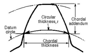
- Circular thickness
- Length of arc between the two sides of a gear tooth, on the specified datum circle.
- Transverse circular thickness
- Circular thickness in the transverse plane.
- Normal circular thickness
- Circular thickness in the normal plane. In a helical gear it may be considered as the length of arc along a normal helix.
- Axial thickness
- In helical gears and worms, tooth thickness in an axial cross section at the standard pitch diameter.
- Base circular thickness
- In involute teeth, length of arc on the base circle between the two involute curves forming the profile of a tooth.
- Normal chordal thickness
- Length of the chord that subtends a circular thickness arc in the plane normal to the pitch helix. Any convenient measuring diameter may be selected, not necessarily the standard pitch diameter.
- Chordal addendum (chordal height)
- Height from the top of the tooth to the chord subtending the circular thickness arc. Any convenient measuring diameter may be selected, not necessarily the standard pitch diameter.
- Profile shift
- Displacement of the basic rack datum line from the reference cylinder, made non-dimensional by dividing by the normal module. It is used to specify the tooth thickness, often for zero backlash.
- Rack shift
- Displacement of the tool datum line from the reference cylinder, made non-dimensional by dividing by the normal module. It is used to specify the tooth thickness.
- Measurement over pins
- Measurement of the distance taken over a pin positioned in a tooth space and a reference surface. The reference surface may be the reference axis of the gear, a datum surface or either one or two pins positioned in the tooth space or spaces opposite the first. This measurement is used to determine tooth thickness.
- Span measurement
- Measurement of the distance across several teeth in a normal plane. As long as the measuring device has parallel measuring surfaces that contact on an unmodified portion of the involute, the measurement wis along a line tangent to the base cylinder. It is used to determine tooth thickness.
- Modified addendum teeth
- Teeth of engaging gears, one or both of which have non-standard addendum.
- Full-depth teeth
- Teeth in which the working depth equals 2.000 divided by the normal diametral pitch.
- Stub teeth
- Teeth in which the working depth is less than 2.000 divided by the normal diametral pitch.
- Equal addendum teeth
- Teeth in which two engaging gears have equal addendums.
- Long and short-addendum teeth
- Teeth in which the addendums of two engaging gears are unequal.

- Undercut
- An undercut is a condition in generated gear teeth when any part of the fillet curve lies inside of a line drawn tangent to the working profile at its point of juncture with the fillet. Undercut may be deliberately introduced to facilitate finishing operations. With undercut the fillet curve intersects the working profile. Without undercut the fillet curve and the working profile have a common tangent.
- Root fillet
- or fillet curve, the concave portion of the tooth profile where it joins the bottom of the tooth space.2
Pitch
[edit]Pitch is the distance between a point on one tooth and the corresponding point on an adjacent tooth.[34] It is a dimension measured along a line or curve in the transverse, normal, or axial directions. The use of the single word pitch without qualification may be ambiguous, and for this reason it is preferable to use specific designations such as transverse circular pitch, normal base pitch, axial pitch.
-
 Pitch
Pitch -
 Tooth pitch
 -
 Base pitch relationships
 -
 Principal pitches


- Circular pitch, p
- Arc distance along a specified pitch circle or pitch line between corresponding profiles of adjacent teeth.
- Transverse circular pitch, pt
- Circular pitch in the transverse plane.
- Normal circular pitch, pn, pe
- Circular pitch in the normal plane, and also the length of the arc along the normal pitch helix between helical teeth or threads.
- Axial pitch, px
- Linear pitch in an axial plane and in a pitch surface. In helical gears and worms, axial pitch has the same value at all diameters. In gearing of other types, axial pitch may be confined to the pitch surface and may be a circular measurement. The term axial pitch is preferred to the term linear pitch. The axial pitch of a helical worm and the circular pitch of its worm gear are the same.
- Normal base pitch, pN, pbn
- An involute helical gear is the base pitch in the normal plane. It is the normal distance between parallel helical involute surfaces on the plane of action in the normal plane, or is the length of arc on the normal base helix. It is a constant distance in any helical involute gear.
- Transverse base pitch, pb, pbt
- In an involute gear, the pitch is on the base circle or along the line of action. Corresponding sides of involute gear teeth are parallel curves, and the base pitch is the constant and fundamental distance between them along a common normal in a transverse plane.
- Diametral pitch (transverse), Pd
- Ratio of the number of teeth to the standard pitch diameter in inches.

- Normal diametral pitch, Pnd
- Value of diametral pitch in a normal plane of a helical gear or worm.

- Angular pitch, θN, τ
- Angle subtended by the circular pitch, usually expressed in radians.
- degrees or radians


Backlash
[edit]Backlash is the error in motion that occurs when gears change direction. It exists because there is always some gap between the trailing face of the driving tooth and the leading face of the tooth behind it on the driven gear, and that gap must be closed before force can be transferred in the new direction. The term "backlash" can also be used to refer to the size of the gap, not just the phenomenon it causes; thus, one could speak of a pair of gears as having, for example, "0.1 mm of backlash." A pair of gears could be designed to have zero backlash, but this would presuppose perfection in manufacturing, uniform thermal expansion characteristics throughout the system, and no lubricant. Therefore, gear pairs are designed to have some backlash. It is usually provided by reducing the tooth thickness of each gear by half the desired gap distance. In the case of a large gear and a small pinion, however, the backlash is usually taken entirely off the gear and the pinion is given full sized teeth. Backlash can also be provided by moving the gears further apart. The backlash of a gear train equals the sum of the backlash of each pair of gears, so in long trains backlash can become a problem.
For situations that require precision, such as instrumentation and control, backlash can be minimized through one of several techniques. For instance, the gear can be split along a plane perpendicular to the axis, one half fixed to the shaft in the usual manner, the other half placed alongside it, free to rotate about the shaft, but with springs between the two-halves providing relative torque between them, so that one achieves, in effect, a single gear with expanding teeth. Another method involves tapering the teeth in the axial direction and letting the gear slide in the axial direction to take up slack.
Standard pitches and the module system
[edit]Although gears can be made with any pitch, for convenience and interchangeability standard pitches are frequently used. Pitch is a property associated with linear dimensions and so differs whether the standard values are in the imperial (inch) or metric systems. Using inch measurements, standard diametral pitch values with units of "per inch" are chosen; the diametral pitch is the number of teeth on a gear of one inch pitch diameter. Common standard values for spur gears are 3, 4, 5, 6, 8, 10, 12, 16, 20, 24, 32, 48, 64, 72, 80, 96, 100, 120, and 200.[55] Certain standard pitches such as 1⁄10 and 1⁄20 in inch measurements, which mesh with linear rack, are actually (linear) circular pitch values with units of "inches"[55]
When gear dimensions are in the metric system the pitch specification is generally in terms of module or modulus, which is effectively a length measurement across the pitch diameter. The term module is understood to mean the pitch diameter in millimetres divided by the number of teeth. When the module is based upon inch measurements, it is known as the English module to avoid confusion with the metric module. Module is a direct dimension ("millimeters per tooth"), unlike diametral pitch, which is an inverse dimension ("teeth per inch"). Thus, if the pitch diameter of a gear is 40 mm and the number of teeth 20, the module is 2, which means that there are 2 mm of pitch diameter for each tooth.[56] The preferred standard module values are 0.1, 0.2, 0.3, 0.4, 0.5, 0.6, 0.8, 1.0, 1.25, 1.5, 2.0, 2.5, 3, 4, 5, 6, 8, 10, 12, 16, 20, 25, 32, 40 and 50.[57]
Gear failure mechanism
[edit]
Gears present several failure mechanism that can happen at the same time according to the rotational speed and the load applied. These mechanism are: wear, scuffing, pitting, micro-pitting, tooth flank fracture and tooth root fatigue fracture.
These mechanisms are due to several phenomena: friction, contact (Hertzian pressure, sliding/rolling), bending fatigue and lack of lubrication. All this phenomena can happen simultaneously and they lead to the failure of the gearbox.
The standard ISO 6336[58] and AGMA 2001[59] provide informations regarding this failure mechanism and define calculation method to verify if a gear is safe from such phenomena. Even if the standards provide these informations they strongly suggest to perform experimental test because the standards can not cover all the possible combinations of geometry, material, heat treatment, ecc.
There are different test to study the behaviour of the gear. Due to the fact that the failure mechanism can happen simultaneously the tested gears are designed in order to isolate only one failure mechanism.[60][61]
Gear model in modern physics
[edit]Modern physics adopted the gear model in different ways. In the nineteenth century, James Clerk Maxwell developed a model of electromagnetism in which magnetic field lines were rotating tubes of incompressible fluid. Maxwell used a gear wheel and called it an "idle wheel" to explain the electric current as a rotation of particles in opposite directions to that of the rotating field lines.[62]
More recently, quantum physics uses "quantum gears" in their model. A group of gears can serve as a model for several different systems, such as an artificially constructed nanomechanical device or a group of ring molecules.[63]
The three wave hypothesis compares the wave–particle duality to a bevel gear.[64]
Gear mechanism in natural world
[edit]
The gear mechanism was previously considered exclusively artificial, but as early as 1957, gears had been recognized in the hind legs of various species of planthoppers[65] and scientists from the University of Cambridge characterized their functional significance in 2013 by doing high-speed photography of the nymphs of Issus coleoptratus at Cambridge University.[66][67] These gears are found only in the nymph forms of all planthoppers, and are lost during the final molt to the adult stage.[68] In I. coleoptratus, each leg has a 400-micrometer strip of teeth, pitch radius 200 micrometers, with 10 to 12 fully interlocking spur-type gear teeth, including filleted curves at the base of each tooth to reduce the risk of shearing.[69] The joint rotates like mechanical gears, and synchronizes Issus's hind legs when it jumps to within 30 microseconds, preventing yaw rotation.[70][71][66] The gears are not connected all the time. One is located on each of the juvenile insect's hind legs, and when it prepares to jump, the two sets of teeth lock together. As a result, the legs move in almost perfect unison, giving the insect more power as the gears rotate to their stopping point and then unlock.[70]
See also
[edit]References
[edit]- ^ Definition of "gear" in the Merriam-Webster Dictionary online, sense (6a). Accessed on 2018-09-20.
- ^ Definition of "gear" in the Oxford Learner's Dictionary online. Accessed on 2024-07-27.
- ^ Definition of "gearwheel" in the Collins English Dictionary online. Accessed on 2024-07-27.
- ^ Definition of "gearwheel" in the Merriam-Webster dictionary online. Accessed on 2018-09-20.
- ^ Definition of "gearwheel" in the Oxford Learner's Dictionary online. Accessed on 2024-07-27.
- ^ a b Definition of "cog" in the Oxford Learner's Dictionary online. Accessed on 2024-07-29.
- ^ Definition of "cog" in the Merriam-Webster Dictionary online. Accessed on 2024-07-29.
- ^ a b Definition of "cog" in the Cambridge Dictionary Plus online. Accessed on 2024-07-29.
- ^ Definition of "cog" in the Collins English Dictionary online. Accessed on 2024-07-29.
- ^ Shuailong Zhang, Mohamed Elsayed, Ran Peng, Yujie Chen (2021): "Reconfigurable multi-component micromachines driven by optoelectronic tweezers". Nature Communications, volume 12, issue 1. doi:10.1038/s41467-021-25582-8
- ^ Matthew Jaster (2013): "MY GEAR is Bigger than YOUR GEAR: Industry Battles it Out for World's Largest Gear Title" Archived 31 December 2024 at the Wayback Machine. Online article from Gear Technology magazine. Archived on 2024-07-30 Archived 31 December 2024 at the Wayback Machine.
- ^ "Levers - Moments, levers and gears - AQA - GCSE Physics (Single Science) Revision - AQA - BBC Bitesize". Bbc.co.uk. 1 January 1970. Retrieved 16 March 2022.
- ^ "Transmission Basics". HowStuffWorks. 27 April 2005.
- ^ Derek J. de Solla Price, On the Origin of Clockwork, Perpetual Motion Devices, and the Compass, p.84
- ^ "Gears from Archimedes, Heron and Dionysius". www.hellenicaworld.com. Retrieved 21 November 2023.
- ^ Norton 2004, p. 462
- ^ Lewis, M. J. T. (1993). "Gearing in the Ancient World". Endeavour. 17 (3): 110–115. doi:10.1016/0160-9327(93)90099-O.
- ^ "The Antikythera Mechanism Research Project: Why is it so important?". Archived from the original on 4 May 2012. Retrieved 10 January 2011.
The Mechanism is thought to date from between 150 and 100 BC
- ^ Owen Jarus (14 April 2022). "World's first computer, the Antikythera Mechanism, 'started up' in 178 B.C., scientists claim". livescience.com. Retrieved 5 June 2022.
- ^ Freeth, Tony. "An Ancient Greek Astronomical Calculation Machine Reveals New Secrets". Scientific American. Retrieved 5 June 2022.
- ^ Joseph Needham (1986). Science and Civilization in China: Volume 4, Part 2, page 298. Taipei: Caves Books, Ltd.
- ^ "vertical dial | British Museum". The British Museum. Retrieved 5 June 2022.
- ^ "The Portable Byzantine Sundial Calendar: The Second Oldest Geared Mechanism in Existence". www.thearchaeologist.org. Retrieved 5 June 2022.
- ^ "Astrolabe By Muhammad Ibn Abi Bakr Al Isfahani".
- ^ Irfan Habib, Economic History of Medieval India, 1200-1500, page 53, Pearson Education
- ^ "Giovanni Dondi's Astrarium, 1364 | cabinet". www.cabinet.ox.ac.uk. Retrieved 5 June 2022.
- ^ "gear (n.)". Etymonline. Retrieved 13 February 2020.
- ^ "Etymology 1: Cog (noun)". Wiktionary. Retrieved 29 July 2019.
- ^ "cog (n.)". Etymonline. Retrieved 13 February 2020.
- ^ Grant, George B. (1893). A Treatise on Gear Wheels (6th, illus. ed.). Lexington, MA; Philadelphia, PA: George B. Grant. p. 21.
- ^ Smith, Zan (2000), "Plastic gears are more reliable when engineers account for material properties and manufacturing processes during design.", Motion System Design, archived from the original on 14 July 2011, retrieved 7 January 2011.
- ^ Radzevich, Stephen P. (2012). Dudley's Handbook of Practical Gear Design and Manufacture (PDF) (2nd ed.). Boca Raton, FL.: CRC Press, an imprint of Taylor & Francis Group. pp. 691, 702.[permanent dead link]
- ^ Fred Eberle (August 2014). "Materials Matter". Gear Solutions: 22.
- ^ a b c d e American Gear Manufacturers Association; American National Standards Institute, Gear Nomenclature, Definitions of Terms with Symbols (ANSI/AGMA 1012-G05 ed.), American Gear Manufacturers Association
- ^ Canfield, Stephen (1997), "Gear Types", Dynamics of Machinery, Tennessee Tech University, Department of Mechanical Engineering, ME 362 lecture notes, archived from the original on 29 August 2008.
- ^ Hilbert, David; Cohn-Vossen, Stephan (1952), Geometry and the Imagination (2nd ed.), New York: Chelsea, p. 287, ISBN 978-0-8284-1087-8.
{{citation}}: ISBN / Date incompatibility (help) - ^ a b McGraw-Hill 2007, p. 743.
- ^ "How Gears Work". howstuffworks.com. 16 November 2000. Retrieved 20 September 2018.
- ^ Machinery's Handbook. New York: Industrial Press. 2012. pp. 2125. ISBN 978-0-8311-2900-2.
- ^ a b c McGraw-Hill 2007, p. 742.
- ^ Khurmi, R. S., Theory of Machines, S.CHAND
- ^ Schunck, Richard, "Minimizing gearbox noise inside and outside the box", Motion System Design.[permanent dead link]
- ^ Vallance & Doughtie 1964, p. 281
- ^ a b Helical gears, archived from the original on 26 June 2009, retrieved 15 June 2009.
- ^ Vallance & Doughtie 1964, p. 287.
- ^ Vallance & Doughtie 1964, pp. 280, 296
- ^ Vallance & Doughtie 1964, p. 290.
- ^ McGraw-Hill 2007, p. 744
- ^ Freeth, Tony; Jones, Alexander (February 2012). "The Cosmos in the Antikythera Mechanism". ISAW Papers (4). Institute for the Study of the Ancient World – via New York University.
- ^ Figliolini, Giorgio; Angeles, Jorge (1 July 2005). "Algorithms for Involute and Octoidal Bevel-Gear Generation". Journal of Mechanical Design. 127 (4): 664–672. doi:10.1115/1.1900147. ISSN 1050-0472.
- ^ Diss. Hünecke, TU Dresden
- ^ Kravchenko A.I., Bovda A.M. Gear with magnetic couple. Pat. of Ukraine N. 56700 – Bul. N. 2, 2011 – F16H 49/00.
- ^ ISO/DIS 21771:2007 : "Gears – Cylindrical Involute Gears and Gear Pairs – Concepts and Geometry", International Organization for Standardization, (2007)
- ^ Gunnar Dahlvig (1982), "Construction elements and machine construction", Konstruktionselement och maskinbyggnad (in Swedish), 7, ISBN 978-9140115546
- ^ a b "W. M. Berg Gear Reference Guide" (PDF). Archived from the original (PDF) on 21 April 2015.
- ^ Oberg, E.; Jones, F. D.; Horton, H. L.; Ryffell, H. H. (2000), Machinery's Handbook (26th ed.), Industrial Press, p. 2649, ISBN 978-0-8311-2666-7.
- ^ "Elements of metric gear technology" (PDF).
- ^ "ISO 6336-1:2019 Calculation of load capacity of spur and helical gears Part 1: Basic principles, introduction and general influence factors". ISO.
- ^ "ANSI/AGMA 2001 - Fundamental Rating Factors and Calculation Methods for Involute Spur and Helical Gear Teeth".
- ^ Mechanical Testing and Evaluation. ASM International. 1 January 2000. doi:10.31399/asm.hb.v08.9781627081764. ISBN 978-1-62708-176-4.
- ^ Halgren, John A.; Wulpi, D. J. (1957). "Laboratory Fatigue Testing of Gears". SAE Transactions. 65: 452–470. ISSN 0096-736X.
- ^ Siegel, Daniel M. (1991). Innovation in Maxwell's Electromagnetic Theory: Molecular Vortices, Displacement Current, and Light. University of Chicago Press. ISBN 978-0521353656.
- ^ MacKinnon, Angus (2002). "Quantum Gears: A Simple Mechanical System in the Quantum Regime". Nanotechnology. 13 (5): 678–681. arXiv:cond-mat/0205647. Bibcode:2002Nanot..13..678M. doi:10.1088/0957-4484/13/5/328. S2CID 14994774.
- ^ Sanduk, M. I. (2007). "Does the Three Wave Hypothesis Imply Hidden Structure?" (PDF). Apeiron. 14 (2): 113–125. Bibcode:2007Apei...14..113S.
- ^ Sander, K. (1957), "Bau und Funktion des Sprungapparates von Pyrilla perpusilla WALKER (Homoptera - Fulgoridae)", Zool. Jb. Jena (Anat.) (in German), 75: 383–388
- ^ a b Burrows, Malcolm; Sutton, Gregory (13 September 2013). "Interacting Gears Synchronize Propulsive Leg Movements in a Jumping Insect". Science. 341 (6151): 1254–1256. Bibcode:2013Sci...341.1254B. doi:10.1126/science.1240284. hdl:1983/69cf1502-217a-4dca-a0d3-f8b247794e92. PMID 24031019. S2CID 24640726.
- ^ Herkewitz, William (12 September 2013), "The First Gear Discovered in Nature", Popular Mechanics
- ^ Lee, Jane J. (12 September 2013), "Insects Use Gears in Hind Legs to Jump", National Geographic, archived from the original on 13 September 2013
- ^ Stromberg, Joseph (12 September 2013), "This Insect Has The Only Mechanical Gears Ever Found in Nature", Smithsonian Magazine, retrieved 18 November 2020
- ^ a b Robertson, Adi (12 September 2013). "The first-ever naturally occurring gears are found on an insect's legs". The Verge. Retrieved 14 September 2013.
- ^ Functioning 'mechanical gears' seen in nature for the first time, PHYS.ORG, Cambridge University
Bibliography
- McGraw-Hill (2007), McGraw-Hill Encyclopedia of Science and Technology (10th ed.), McGraw-Hill Professional, ISBN 978-0-07-144143-8.
- Norton, Robert L. (2004), Design of Machinery (3rd ed.), McGraw-Hill Professional, ISBN 978-0-07-121496-4.
- Vallance, Alex; Doughtie, Venton Levy (1964), Design of machine members (4th ed.), McGraw-Hill.
- Industrial Press (2012), Machinery's Handbook (29th ed.), ISBN 978-0-8311-2900-2
- Engineers Edge, Gear Design and Engineering Data.
Further reading
[edit]- American Gear Manufacturers Association; American National Standards Institute (2005), Gear Nomenclature: Definitions of Terms with Symbols (ANSI/AGMA 1012-F90 ed.), American Gear Manufacturers Association, ISBN 978-1-55589-846-5.
- Buckingham, Earle (1949), Analytical Mechanics of Gears, McGraw-Hill Book Co..
- Coy, John J.; Townsend, Dennis P.; Zaretsky, Erwin V. (1985), Gearing (PDF), NASA Scientific and Technical Information Branch, NASA-RP-1152; AVSCOM Technical Report 84-C-15.
- Kravchenko A.I., Bovda A.M. Gear with magnetic couple. Pat. of Ukraine N. 56700 – Bul. N. 2, 2011 – F16H 49/00.
- Sclater, Neil. (2011). "Gears: devices, drives and mechanisms." Mechanisms and Mechanical Devices Sourcebook. 5th ed. New York: McGraw Hill. pp. 131–174. ISBN 9780071704427. Drawings and designs of various gearings.
- "Wheels That Can't Slip." Popular Science, February 1945, pp. 120–125.
External links
[edit]- Geararium. Museum of gears and toothed wheels - antique and vintage gears, sprockets, ratchets and other gear-related objects.
- Kinematic Models for Design Digital Library (KMODDL) - movies and photos of hundreds of working models at Cornell University
- Short historical account on the application of analytical geometry to the form of gear teeth
- Mathematical Tutorial for Gearing (Relating to Robotics)
- American Gear Manufacturers Association
- Gear Technology, the Journal of Gear Manufacturing
| International | |
|---|---|
| National | |
| Other | |
History and Etymology
Historical Development
The earliest known gear-like mechanisms date to around 3000 BCE in China, used in two-wheeled chariots with wooden gear trains for propulsion.[5] Wooden cogs also appeared in early water wheels for power transmission in irrigation and grinding. These rudimentary forms evolved into more sophisticated bronze toothed gears by the third century BCE in Alexandria, Greece, where mechanics like those influenced by Archimedes developed them for lifting devices and automata.[12] A landmark example is the Antikythera mechanism, dated to approximately 150–100 BCE, an analog computer recovered from a Greek shipwreck that employed over 30 precision gears to model astronomical positions, predict eclipses, and track calendars, representing the first known complex gear train in history.[13] During the medieval period, Cistercian monks advanced mechanical technology by constructing water mills with geared systems for automated milling.[14] In Europe, clockwork innovations including escapements and foliot regulators were developed for reliable timekeeping devices. A pivotal contribution came from Richard of Wallingford, abbot of St. Albans, who in the 1320s designed an astronomical clock featuring an oval gear wheel to simulate the Sun's irregular motion, along with epicyclic gears for planetary tracking, marking an early application of non-circular gearing in Europe.[15] The Industrial Revolution catalyzed widespread gear adoption in power machinery, with James Watt's 1781 sun-and-planet gear enabling rotary motion from his steam engine's linear reciprocation, doubling shaft revolutions per cycle and powering factories, mills, and early locomotives.[16] This epicyclic design, patented to circumvent crank patents, facilitated the mechanization of production lines. In the 20th century, hypoid gears, invented by Ernest Wildhaber in the early 1920s, introduced offset axes for smoother, more efficient power transfer, revolutionizing automotive differentials by allowing lower propeller shafts in vehicles like the 1926 Packard.[17] By the 1980s, computer-aided design (CAD) transformed gear engineering, with interactive software enabling precise modeling of bevel and helical gears, reducing design iterations and improving tooth profiles for noise reduction and load capacity.[18] Recent developments through 2025 have focused on additive manufacturing for custom gears, enabling complex topologies like internal cooling channels and lightweight lattices unattainable by traditional machining. A 2025 study on 316L stainless steel gears manufactured via laser powder bed fusion (LPBF) investigated their wear mechanisms compared to conventionally made gears under lubricated conditions, showing that LPBF gears can achieve acceptable wear performance with appropriate post-processing.[19] In electric vehicles (EVs), single-speed reduction gears with high-efficiency helical designs have optimized torque delivery from motors, contributing to extended range and reduced noise in models like those from 2020 onward, amid a market shift toward electrification.[20] Similarly, in robotics, precision cycloidal and harmonic gears have advanced joint modules for collaborative robots, supporting higher payloads and dexterity in automation tasks, with the robot gears market growing from $141 million in 2024 to a projected $232 million by 2032 due to AI-integrated systems.[21]Etymology and Terminology Origins
The term "gear" traces its roots to Old English gearwe, denoting clothing, apparel, or equipment, which evolved in Middle English around 1200 CE to encompass general tools and apparatus before acquiring its mechanical connotation of a toothed wheel by the 1520s.[22] This shift reflected the device's role as essential "equipment" in machinery for transmitting motion, with the first documented mechanical usage appearing in English texts from that period. The word "pinion," referring to a small gear meshing with a larger one, entered English in the 1650s from French pignon, a 16th-century term for a pointed gable or summit, ultimately derived from Vulgar Latin pinnionem, an augmentative of Latin pinna meaning "feather" or "battlement," evoking the idea of small, projecting teeth.[23] Similarly, "spur gear" arose in the early 19th century (first recorded 1815–25), with "spur" drawing from the Old English spora for the spiked projection on a horseman's boot, analogizing the straight, radial teeth that project parallel to the gear's axis.[24] "Helical," describing gears with angled, spiral teeth, stems from the Greek helix (ἕλιξ), meaning "spiral" or "twist," via Latin helix, entering English scientific terminology in the 16th century to denote coiled or winding forms.[25] The term "worm" for a screw-like gear dates to the 18th century, deriving from Old English wyrm, originally signifying a serpent or crawling creature, due to the device's elongated, twisting shape resembling an earthworm. Multilingual influences are evident in technical lexicon, such as German Zahnrad ("tooth wheel"), combining Old High German zan ("tooth") and Proto-Germanic radą ("wheel"), a descriptive compound that parallels Latin rota dentata ("toothed wheel") from classical engineering texts.Materials and Manufacturing
Gear Materials
The selection of materials for gear construction is driven by key performance factors including mechanical strength, surface hardness, fatigue endurance under cyclic loading, and resistance to environmental degradation such as corrosion, all of which directly influence gear durability, efficiency, and load-bearing capacity.[26] Hardness, a primary indicator of wear resistance, is typically quantified using the Rockwell C scale (HRC) for hardened surfaces or the Brinell scale (HB) for softer materials, with gear teeth often targeted at 50-65 HRC to balance abrasion resistance and toughness.[27] Fatigue resistance ensures longevity in applications involving repeated stress, while corrosion resistance prevents degradation in harsh conditions, such as marine environments where stainless steels like AISI 316 are preferred for their molybdenum-enhanced protection against pitting from saltwater exposure.[28] Among common metallic materials, low-carbon steels such as AISI 1020 provide ductility and cost-effectiveness, making them suitable for lightly loaded gears where formability during shaping is prioritized over extreme hardness.[29] Alloy steels, exemplified by AISI 8620, are favored for case-hardening applications like carburizing, where a low-carbon core (around 0.20% C) allows for a tough interior while the surface achieves high hardness (up to 60 HRC) for improved wear performance in automotive and industrial transmissions.[30] Cast irons, particularly gray cast iron, excel in damping vibrations due to their graphite microstructure, which absorbs energy and reduces noise in low-speed, high-torque setups like machinery bases, though they exhibit lower tensile strength (typically 200-400 MPa) compared to steels.[28] Non-metallic materials expand gear options for specialized needs; plastics like nylon (polyamide) offer inherent lubricity and quiet operation by minimizing metal-to-metal contact noise, ideal for low-load, high-speed consumer products such as printers, with tensile strengths around 80 MPa but limited to temperatures below 100°C to avoid softening.[31] Composites, such as carbon fiber-reinforced polymers, deliver exceptional strength-to-weight ratios (Young's modulus up to 350 GPa) for aerospace gears, reducing overall system mass by approximately 20% compared to steel equivalents while maintaining stiffness under dynamic loads, though they require careful design to mitigate delamination risks.[32][33] By 2025, advanced materials like titanium alloys (e.g., Ti-6Al-4V) have gained traction for high-performance gears in aerospace and biomedical fields, providing a superior strength-to-weight ratio (tensile strength ~900 MPa at half steel's density) and corrosion resistance without frequent lubrication, often enhanced via ion nitriding for surface hardness up to 1,000 HV.[34] Ceramics, including zirconia-toughened alumina, demonstrate outstanding wear resistance in high-heat environments (up to 1,200°C), with hardness exceeding 1,500 HV that minimizes abrasion in precision instruments, though their brittleness necessitates hybrid designs with metallic cores for impact tolerance.[35] Heat treatments significantly modify these material properties; annealing relieves internal stresses and enhances ductility for easier machining, while quenching rapidly cools austenitized steel to form martensite, boosting hardness and fatigue strength but requiring tempering to avoid brittleness.[36] Overall, material choices must align with manufacturing compatibility, such as castability for irons or machinability for alloys, to achieve precise tooth profiles without excessive distortion.[26]Manufacturing Processes
Gear manufacturing encompasses a range of processes tailored to achieve specific geometries, tolerances, and production volumes, primarily divided into machining, forming, finishing, and emerging additive techniques. These methods ensure gears meet standards such as those set by the American Gear Manufacturers Association (AGMA) for quality and performance.[37]Machining Processes
Machining involves subtractive techniques to cut gear teeth from a blank, suitable for high-precision applications. Hobbing is a primary method for producing spur and helical gears, utilizing a rotating hob cutter that generates teeth through continuous indexing motion between the tool and workpiece. This process excels in high-volume production due to its efficiency and ability to handle various module sizes.[38][39] Milling employs an end mill or form cutter to machine gear teeth in a series of passes, offering versatility for prototyping low-volume runs or custom profiles where hobbing is impractical. It is particularly useful for gears with non-standard tooth forms but requires more setup time compared to hobbing.[40][39] Shaping uses a reciprocating cutter to generate teeth on internal or external gears, ideal for large-diameter gears where hobbing machines may be limited by size constraints. The process involves linear motion of the cutter across the blank, producing accurate profiles for heavy-duty applications.[39][41]Forming Processes
Forming methods create gears by shaping material without extensive cutting, often for cost-effective production of simpler or smaller components. Sand casting pours molten metal into a sand mold to form gear blanks, commonly used for prototypes or low-volume large gears due to its low tooling costs and ability to handle complex shapes. Die casting, a variant, injects metal under pressure into reusable dies for higher precision prototypes, suitable for aluminum or zinc alloys in preliminary testing.[42][43] Powder metallurgy compacts metal powders into gear shapes under high pressure, followed by sintering to bond the particles, enabling the production of small, precise gears with integrated features like hubs. This net-shape process minimizes waste and is favored for automotive transmission components requiring uniform density.[44][45]Finishing Processes
Finishing refines gear surfaces post-rough machining or forming to achieve required accuracy and surface quality. Grinding uses abrasive wheels to remove material from hardened gears, attaining AGMA quality classes Q6 to Q12 by correcting profile errors and improving tooth finish. Lapping pairs mating gears with an abrasive slurry to polish contact surfaces, enhancing noise reduction and load distribution while achieving sub-micron tolerances. These steps are essential for high-performance gears, where surface roughness directly impacts efficiency and lifespan.[46][47][37]Modern Methods
Additive manufacturing, including 3D printing and laser sintering, builds gears layer-by-layer from metal powders, enabling complex geometries like non-circular or lightweight internal structures unattainable via traditional subtraction. As of 2025, techniques such as selective laser melting produce functional metal gears for aerospace and prototyping, with AGMA guidelines addressing material qualification and process validation. Laser sintering specifically fuses powders with a laser for high-density parts, reducing support structures in intricate designs.[48][49] Process selection depends on production volume, precision needs, and cost; for instance, hobbing is preferred for high-volume spur gears due to its speed and repeatability, while additive methods suit low-volume custom parts despite higher per-unit costs. Material compatibility influences choices, as processes like powder metallurgy require sinterable alloys for optimal density.[50]Basic Principles and Comparisons
Ideal Gear Model
Gears are mechanical elements consisting of toothed wheels that engage to transmit rotary motion between shafts while maintaining a constant angular velocity ratio, as dictated by the fundamental law of gearing.[51] This law ensures that the common normal at the point of contact between meshing teeth passes through a fixed pitch point, enabling uniform motion transfer without slippage or variation in speed ratio.[52] In the ideal model, gears are treated as rigid bodies with teeth that remain in continuous contact, assuming no backlash (clearance between teeth), and incompressible tooth material to prevent deformation under load.[53] The basic kinematics of an ideal gear pair relate the angular velocities and of the driving and driven gears to the number of teeth and , respectively, via the ratio , where the negative sign indicates inversion of rotational direction for external meshing.[51] The pitch circles, imaginary circles tangent to the teeth at the pitch point where pure rolling occurs, have diameters proportional to the number of teeth, reinforcing that the velocity ratio equals the inverse ratio of these diameters.[51] Correspondingly, the torque relation follows from power conservation, yielding (in magnitude), as the ideal model assumes 100% efficiency with no losses, preserving mechanical power .[54] Geometric prerequisites for the ideal model include the pitch circle and the pressure angle, defined as the angle between the tooth profile and the radial line at the pitch point. Standard pressure angles are 20° (most common in modern designs) or 14.5° (used in older systems), influencing tooth strength and contact smoothness.[55] These elements ensure conjugate action, where tooth profiles generate the required constant velocity ratio under perfect conditions.[51]Comparison with Other Drive Mechanisms
Gears provide higher precision and load capacity compared to belt and chain drives, making them ideal for applications requiring exact timing and heavy torque transmission, though they necessitate precise alignment and regular lubrication to prevent wear.[56] In contrast, belt drives excel in quieter operation and lower initial costs, particularly for spanning longer distances between shafts without the need for tight alignment, but they suffer from potential slippage under high loads, reducing accuracy.[57] Chain drives offer a balance with positive engagement similar to gears, avoiding slippage while handling moderate distances more economically than gears, yet they generate more noise and vibration, requiring periodic lubrication and tension adjustments.[56] Unlike friction drives, which rely on surface contact and can experience variability in torque transmission due to slip, wear, or contamination, gears ensure positive drive through meshing teeth, delivering consistent motion without loss of synchronization even under varying loads.[58] This reliability makes gears preferable for high-precision tasks, whereas friction drives are simpler and cheaper for low-torque, variable-speed scenarios but less efficient overall due to energy losses from slipping.[59] Gears are suited for continuous rotary motion between parallel or intersecting shafts, enabling efficient power transfer in compact setups, while linkages and cams are better for intermittent, linear, or oscillating motions, such as in reciprocating engines or automated machinery where non-continuous action is required.[60] For instance, cams convert rotary input to precise follower displacement for valve timing, but they introduce higher friction and complexity compared to gears' smooth, ongoing rotation. In applications, gears dominate compact, high-torque environments like automotive transmissions, where they achieve ratios up to 10:1 per stage for efficient speed reduction.[61] Belts, conversely, support variable speeds in systems like HVAC fans, allowing easy adjustment without backlash.[62] Efficiency trade-offs highlight gears' superiority, typically reaching 95-99% per stage due to minimal sliding friction in well-lubricated meshing, compared to belts at 95-98% and chains at 95-98%, where losses arise from bending and articulation.[56]| Drive Mechanism | Efficiency Range | Key Strengths | Key Weaknesses |
|---|---|---|---|
| Gears | 95-99% | High precision, high load capacity, positive drive | Requires lubrication and precise alignment |
| Belts | 95-98% | Quiet, low cost, suitable for long distances | Slippage under load, lower precision |
| Chains | 95-98% | Positive drive, moderate distance capability | Noisy, needs maintenance |
| Friction Drives | Variable (typically lower due to slip) | Simple, inexpensive | Slip under load, affected by wear |
| Linkages/Cams | Variable (context-dependent) | Suited for intermittent/linear motion | Higher friction, not for continuous rotary |
Gear Geometry by Axis Configuration
Parallel Axis Gears
Parallel axis gears refer to gear systems in which the rotational axes of the mating gears are parallel to each other, enabling the transmission of motion and torque between coplanar shafts without angular misalignment. The most straightforward and widely used configuration in this category is the spur gear, characterized by straight teeth that run parallel to the gear axis, providing a simple and robust design for low- to moderate-speed applications. Parallel axis gears also include helical gears, which feature teeth angled relative to the axis for smoother meshing while maintaining parallel shafts. These gears operate on the principle of involute tooth profiles, ensuring constant velocity ratio during meshing, where the ideal velocity ratio equals the inverse of the ratio of the number of teeth on the driven gear to the driving gear.[63][51][64] In terms of geometry, the center distance between the axes of two external meshing spur gears is calculated as , where and are the pitch diameters of the pinion and gear, respectively; the pitch diameter itself is defined as the diameter of the pitch circle, which passes through the point where the pitch circles of mating gears are tangent. This arrangement ensures proper meshing without interference, with the pitch diameters determined by the number of teeth and the chosen diametral pitch. Tooth contact in spur gears occurs along a straight line parallel to the axis, extending across the full face width of the teeth, which distributes the load uniformly but can lead to concentrated stresses at the tooth roots. The pressure angle , typically standardized at 20° for most applications, defines the angle between the line of action (the direction of force transmission) and the tangent to the pitch circle, influencing the radial and tangential components of the transmitted force.[65][66][67][68] Spur gears find extensive use in automotive transmissions for speed reduction and torque multiplication, as well as in precision mechanisms like clocks and watches, where their operation within enclosed housings mitigates inherent noise levels. In clock applications, the simplicity of spur gears allows for compact assemblies with reliable timekeeping over extended periods. These gears excel in environments requiring high efficiency, often achieving 98-99% power transmission rates due to minimal sliding friction during meshing.[69][70] The primary advantages of parallel axis spur gears include ease of manufacturing through processes like hobbing or shaping, which require straightforward tooling, and the absence of axial thrust loads that would necessitate additional bearings, simplifying overall system design. However, a key limitation is the noise and vibration generated from the abrupt engagement and disengagement of straight teeth, particularly at higher speeds above 1000 rpm, which can reduce operational smoothness in open environments.[71][67][72]Crossed Axis Gears
Crossed axis gears, also known as intersecting axis gears, are designed for shafts that intersect at a point, typically at a 90-degree angle, enabling efficient power transmission between non-parallel axes.[64] The primary type is the bevel gear, where the pitch surfaces form truncated cones that are tangent to each other at a common apex point, allowing the gears to mesh smoothly while changing the direction of rotation.[73] In straight bevel gears, the teeth are cut straight and radial to the cone axis, providing a simple geometry suitable for moderate speeds and loads. Spiral bevel gears, however, feature curved teeth that gradually engage, similar to helical gears, resulting in smoother operation, reduced noise, and higher load capacity due to increased contact area during meshing.[51] The kinematics of crossed axis gears rely on the geometry of the pitch cones to determine motion transmission. The velocity ratio is given by the inverse ratio of the number of teeth on the gears or equivalently the ratio of their pitch cone distances from the apex, ensuring constant angular velocity regardless of the shaft angle.[73] The shaft angle, usually set at 90 degrees for right-angle applications, is the sum of the pitch cone angles of the two gears, which must be precisely machined to maintain proper backlash and alignment. This configuration allows for precise control of speed and torque redirection without slippage, adhering to the fundamental law of gearing that the common normal at the point of contact must pass through the pitch point.[74] Applications of crossed axis gears are prevalent in scenarios requiring compact right-angle power transmission, such as automotive differentials where bevel gears enable wheel speed differentiation during turns, and in industrial machinery like right-angle drives for conveyors and mixers.[51] In vehicle differentials, a pair of bevel gears, often with a pinion and ring gear, distributes torque to the axles while accommodating varying rotational speeds. These gears are also used in hand tools, robotics, and aerospace transmissions for their ability to fit into tight spaces.[75] One key advantage of crossed axis gears is their compact design, which facilitates efficient right-angle turns in mechanisms where space is limited, outperforming belt drives or chains in precision and load-handling capability.[64] However, they generate significant axial thrust loads due to the angled teeth, necessitating robust thrust bearings to prevent misalignment and wear, which adds complexity and cost to the assembly. Additionally, manufacturing bevel gears requires specialized equipment like Gleason generators for accurate cone shaping, making them more expensive than parallel axis counterparts.[51] Despite these limitations, advancements in spiral bevel designs have mitigated noise and vibration issues, enhancing their suitability for high-speed applications.[75]Skew Axis Gears
Skew axis gears, also known as non-parallel and non-intersecting axis gears, are mechanical components designed to transmit motion and power between shafts whose axes neither intersect nor run parallel to each other.[76] This configuration introduces a skew angle between the axes, enabling compact arrangements in applications requiring right-angle or oblique power transmission without axial intersection. Primary variants include hypoid gears and worm gears, with the former featuring curved, non-conical teeth that accommodate an axial offset for enhanced performance.[77] In these gears, motion transfer occurs through sliding contact along the tooth flanks, distinguishing them from rolling-dominated parallel or crossed axis systems. Hypoid gears represent a key subtype of skew axis gears, characterized by axes that are skewed with a deliberate offset distance, often denoted as , which shifts the pinion axis relative to the gear axis—typically above or below the centerline—to optimize mesh geometry. This offset enables smoother engagement and reduced noise compared to traditional bevel gears, as the teeth follow hyperbolic paths that allow for gradual contact progression. Kinematically, hypoid gears achieve complex velocity ratios determined by the number of teeth and the skew geometry, with the offset directly influencing sliding velocities and contact patterns during meshing; for instance, larger offsets can increase the sliding component, affecting efficiency and load distribution.[78] The design ensures constant angular velocity transmission under ideal conditions, though real-world misalignments introduce minor fluctuations.[79] In applications, skew axis gears like hypoids are prevalent in automotive rear differentials, where the offset facilitates lower vehicle floor heights by positioning the driveshaft below the axle line, as seen in ring-and-pinion setups for rear-wheel-drive vehicles.[80] They also appear in power tools and industrial machinery requiring high torque in compact, right-angle configurations. Advantages include quiet operation due to progressive tooth engagement, superior torque capacity from larger pinion sizes, and reduction ratios typically ranging from 5:1 to 60:1 for hypoids, with worm gears capable of even higher ratios up to 300:1 or more, making them suitable for heavy-duty loads.[81][82] However, the inherent sliding contact leads to higher wear rates on tooth surfaces compared to pure rolling gears, necessitating robust lubrication and precise manufacturing to mitigate fatigue and efficiency losses.[77] Worm gears, another skew axis variant, provide setups for high-ratio reductions but share similar sliding challenges.[76]Tooth Design and Orientation
Internal and External Teeth
Gears are classified based on the positioning of their teeth relative to the gear body, with external and internal configurations representing the primary orientations for cylindrical and conical designs. External gears feature teeth that project radially outward from the surface of a cylindrical or conical body, enabling them to mesh directly with the teeth of another external gear to transmit motion and torque between parallel or intersecting shafts.[83] This outward tooth arrangement is the standard for most conventional gear pairs, allowing for straightforward manufacturing and assembly in open drive systems such as those found in industrial machinery and automotive transmissions.[84] In contrast, internal gears, also known as ring or annular gears, have teeth cut on the inner surface of a cylindrical ring, pointing inward toward the center. These teeth typically mesh with an external pinion gear positioned inside the ring, creating a compact assembly suitable for applications requiring high torque in limited space, such as planetary gear systems.[85] Geometrically, the pitch circle of an internal gear is larger than that of the meshing external pinion, and the addendum and dedendum are reversed relative to the external configuration: the addendum lies inward from the pitch circle, while the dedendum extends outward.[86] This reversal accommodates the internal meshing, where the external pinion's addendum engages the internal gear's dedendum.[87] External gears are widely applied in open drive mechanisms, such as conveyor systems and simple speed reducers, due to their ease of access for lubrication and inspection. Internal gears excel in epicyclic or planetary configurations, where the ring gear's design allows multiple planet gears to orbit within it, achieving significant size reduction while maintaining high load capacity.[85] A key advantage of internal gears is their ability to minimize the overall external diameter of the assembly, enabling more compact machinery without sacrificing torque transmission.[83] However, internal gear designs carry a higher risk of undercutting, particularly on the meshing pinion's teeth during generation, which can reduce strength, contact ratio, and operational smoothness if the pinion has fewer than a certain number of teeth.[88] This limitation often necessitates profile modifications or specialized manufacturing techniques to mitigate interference between the external gear's addendum and the internal gear's dedendum.[87]Crown Gear Configuration
A crown gear, also known as a contrate gear, is a specialized form of bevel gear characterized by a pitch cone angle of 90 degrees, resulting in a planar pitch surface rather than a conical one.[74] The gear body is typically disc-shaped, with teeth projecting axially from the periphery of one flat face, oriented perpendicular to the plane of the disc.[89] This geometry enables the crown gear to mesh effectively with a mating bevel pinion at a right angle or with a straight rack, analogous to how a rack meshes with a spur gear but adapted for perpendicular axis configurations.[89] In terms of kinematics, the crown gear transmits motion at a 90-degree angle between axes, converting rotary input to either linear output when paired with a rack or to orthogonal rotary output when engaged with a bevel pinion.[74] The velocity ratio is determined by the number of teeth on the crown gear relative to the pinion or rack pitch, ensuring constant angular velocity under ideal conditions without sliding if involute profiles are used.[89] This setup provides efficient power transfer in crossed-axis arrangements, though the flat face limits the contact area compared to conical bevel pairs. They are also utilized in certain mechanical clocks, particularly in escapement assemblies such as the verge and foliot, to regulate intermittent motion and timekeeping.[90] The primary advantage of the crown gear configuration lies in its simplicity for achieving perpendicular motion conversion in space-constrained designs, allowing easy integration with standard bevel pinions or racks.[89] However, the axial tooth orientation on a flat face results in limited load capacity, as the teeth experience higher concentrated stresses and are prone to wear under heavy loads or high speeds, restricting use to low-to-moderate power transmissions.[74]Straight Tooth Design
Straight tooth design in gears refers to teeth that run parallel to the axis of rotation, creating a cylindrical gear profile suitable for transmitting motion between parallel shafts. These teeth commonly employ an involute curve for their profile, which generates a line of action that ensures conjugate motion and constant angular velocity during engagement. Tooth depth can vary between full-depth and stub forms; full-depth teeth adhere to standard proportions where the addendum equals one module and the dedendum is 1.25 modules, while stub teeth reduce these dimensions (typically to 0.8 module addendum and dedendum) to enhance strength and minimize undercutting risks in smaller pinions.[91][92][93] In meshing, straight teeth initiate contact at a point on the leading flank that progresses along a straight line of action to form full line contact across the tooth height, enabling efficient load distribution but with sudden engagement that produces impact forces. This abrupt meshing generates higher noise and vibration levels, as the teeth collide radially rather than gradually sliding into position.[94][9][95] Straight tooth gears find primary applications in low-speed machinery, such as ball mills, kilns, and conveyor systems, where their structural simplicity supports high-torque needs without requiring advanced noise mitigation. In these contexts, the design's straightforwardness prioritizes reliability and ease of maintenance over acoustic performance.[96][97][98] Key advantages include simplified manufacturing via processes like hobbing or gear shaping, which reduces production costs and time compared to more complex profiles, along with zero axial thrust, eliminating the need for thrust bearings. Limitations encompass elevated vibration that can accelerate wear in prolonged operations and increased noise unsuitable for precision or high-speed environments.[99][84][95]Helical Tooth Design
Helical gears are characterized by teeth that are inclined at an angle to the axis of rotation, forming a helical pattern around the gear circumference. This geometry is defined by the helix angle ψ, which typically ranges from 8° to 45°, allowing for customization based on speed, load, and noise requirements. The normal pressure angle, measured in the plane perpendicular to the tooth surface, is commonly 20°, while the transverse pressure angle is derived from it using the relation involving the helix angle. Helical gears are produced in left-hand or right-hand configurations, with the hand determined by the direction of the helix slope when viewed along the axis; for parallel-axis applications, mating gears must have opposite hands to ensure proper meshing.[100][101] During operation, helical teeth engage along a line of contact that progresses from one end of the tooth to the other, resulting in smoother meshing than straight-tooth designs. This progressive contact involves multiple teeth simultaneously, distributing forces more evenly and achieving a higher contact ratio, which minimizes impact loads and significantly reduces noise and vibration levels. The line contact also enhances the gear's ability to handle dynamic loads at higher speeds.[101] Helical gears find extensive use in high-speed applications, such as turbines operating up to 10,000 rpm and automotive transmissions for parallel shafts, where their quiet performance and efficiency are critical. These gears support pitch line velocities exceeding 9,000 feet per minute, making them suitable for power transmission in demanding environments. One key advantage is their increased load capacity, as the angled teeth allow more surface area for force distribution across several teeth in contact, enabling higher torque transmission compared to equivalent spur gears.[102][101] A primary limitation of helical gears is the generation of axial thrust due to the helical inclination, which acts parallel to the shaft and necessitates robust thrust bearings to maintain alignment and prevent excessive wear. The magnitude of this axial thrust force is given by where is the transmitted torque, is the helix angle, and is the pitch diameter; higher helix angles amplify this force, requiring careful design trade-offs. Double helical configurations address this thrust by incorporating opposing helix pairs but are treated as a distinct extension.[73]Double Helical Tooth Design
Double helical gears, also known as herringbone gears, consist of two sets of helical teeth with opposite helix directions machined into a single gear blank, forming a V-shaped pattern that meets at a central groove.[74] This design operates on parallel axes and builds on helical gear principles by incorporating mirror-image helices to achieve balanced operation.[103] The geometry features two mirror-image helical sections, one right-handed and one left-handed, converging at a central groove that separates the tooth sets and reduces the effective face width.[74] This configuration produces zero net axial thrust, as the forces from each helical section cancel each other out.[103] In meshing, the opposing helices ensure continuous tooth contact across the face width, providing smooth operation and high load-carrying capacity suitable for heavy-duty applications.[74] The design's strength allows it to handle high torques at elevated speeds, with pitch-line velocities up to 200 m/s.[74] These gears find primary applications in large turbines, rolling mills, cement mills, and crushers, where parallel-axis transmission of substantial power is required.[103] They are particularly valued in heavy industrial settings for their ability to manage high loads without axial complications.[74] Key advantages include the elimination of thrust loads on shafts, obviating the need for end bearings to manage axial forces.[103] This results in simpler shaft designs and improved efficiency, typically ranging from 97% to 99.5%.[74] Limitations arise from the intricate manufacturing process, which involves precise machining of the dual helices and can lead to apex runout issues, increasing production costs.[104] Alignment between mating gears is critical to prevent uneven loading and potential noise increases of up to 4 dB compared to single helical designs due to axial shuttling.[103]Worm Gear Tooth Design
Worm gears feature a distinctive tooth design where the worm resembles a screw with helical threads, typically configured as single-start or double-start, and the mating worm wheel has concave, enveloping teeth that wrap around the worm to facilitate meshing. The worm's thread is cut with a specific lead, defined as the axial advance per revolution, which directly influences the lead angle λ—the angle formed between the thread helix on the pitch cylinder and a plane perpendicular to the worm's axis. This geometry enables the worm to drive the wheel in a skew axis arrangement, with the wheel's teeth shaped to conjugate with the worm's helical profile for efficient power transmission.[105][106][107] The meshing action in worm gears primarily involves sliding contact rather than rolling, as the worm's threads slide along the enveloping faces of the wheel's teeth, generating high friction but allowing for substantial speed reduction. This sliding meshing supports exceptionally high gear ratios, commonly ranging from 5:1 to 300:1, achieved by varying the number of starts on the worm relative to the wheel's tooth count, making worm gears ideal for compact, high-torque applications.[108][109][110] In practice, worm gears find prominent use in elevators, where their skew axis configuration and high reduction ratios enable precise vertical motion control, and in tuning mechanisms for devices requiring fine adjustments under load. Key advantages include inherent self-locking capability—preventing backdriving when the lead angle λ is sufficiently low relative to the friction coefficient—and a compact form factor suitable for space-constrained environments. However, the reliance on sliding contact leads to lower efficiency, typically 50% to 90%, primarily due to frictional losses that generate heat and necessitate robust lubrication.[111][112][108]Tooth Profile Types
Artisanal and Cage Profiles
Artisanal gear profiles refer to hand-crafted tooth forms, often produced by filing or shaping materials like wood or soft metals in pre-industrial settings, where precision tools were unavailable. These profiles, common in early 19th-century American clocks from makers like Eli Terry in Connecticut, utilized wooden wheels and pinions to reduce costs compared to brass alternatives.[113][114] Hand-filers shaped irregular curves approximating cycloidal paths to ensure basic meshing, allowing custom fits for antique timepieces without standardized machinery.[115] This low-accuracy approach prioritized affordability and ease of local repair in rural workshops, though it resulted in higher friction and uneven wear over time.[116] Cage profiles, also known as lantern or trammel gears, feature skeletal structures with cylindrical pins or rods serving as teeth instead of solid cuts, forming a lightweight cage-like assembly parallel to the axle. Originating in historical mechanisms such as early European clocks and mills, these designs simplified construction by inserting wooden or metal pins into end discs, meshing with opposing gears via point contact.[117][90] Geometrically, they represent an approximate cycloidal variant with discrete point teeth, enabling low-precision operation in light-duty applications like toy models and decorative historical devices.[118] In applications such as 18th- and 19th-century wooden clocks, both artisanal and cage profiles offered advantages including low material costs and straightforward handmade production, making them accessible for mass-produced mantel clocks before industrialized metalworking.[113] However, their limitations include rapid wear from point loading and inefficiency due to higher sliding friction, contrasting sharply with the smooth conjugate action of mathematically precise profiles.[119] These profiles thus suited intermittent, non-critical uses in historical toys and models, where durability was secondary to economic viability.[115]Mathematical Profiles for Parallel and Crossed Axes
The involute profile represents the standard mathematical tooth form for gears operating on parallel or crossed axes, enabling efficient power transmission with minimal wear. The involute curve was developed in the 18th century and ensures conjugate action between meshing teeth, maintaining a constant angular velocity ratio regardless of minor variations in operating conditions.[120] This profile is generated geometrically by unwrapping an inextensible string from a base circle of radius , with the path traced by the string's end point defining the tooth flank.[51] The parametric equations for the involute curve in Cartesian coordinates, relative to the base circle center, are derived from this unwrapping process: where is the roll angle in radians, measured from the point where the string is tangent to the base circle. These equations describe a curve that is straight-line generated, approximating the ideal form for smooth meshing in spur and helical gears with parallel axes. The base circle radius relates to the pitch radius and pressure angle by , ensuring the profile intersects the line of action properly.[121] Conjugate action in involute gears arises from the property that the common normal to the tooth surfaces at the point of contact always passes through the pitch point, the intersection of the line of centers with the pitch circles. This maintains a constant pressure angle (typically 20° for modern designs) throughout the meshing cycle, resulting in uniform transmission of force and constant velocity ratio between the driving and driven gears. The pressure angle defines the orientation of the line of action, along which the normal force acts, and its constancy prevents fluctuations in torque that could cause vibration or noise.[122][51][123] For crossed axes, where the gear shafts intersect at an angle (e.g., in crossed helical gears) or are offset (non-intersecting), the basic involute profile requires modifications to achieve proper meshing. In hypoid gears, which accommodate offset axes for applications like automotive differentials, the involute is adapted through geometric transformations during generation, such as using face-milling or face-hobbing to create non-developable surfaces that approximate involute action while compensating for the shaft offset. These modifications preserve conjugate meshing by adjusting the tooth curvature and sliding ratios, though they introduce slight deviations from the pure parallel-axis involute.[124] Standard tooth dimensions for full-depth involute profiles follow module-based conventions, where the addendum (height above the pitch circle) is and the dedendum (depth below the pitch circle) is , with as the module (pitch diameter divided by number of teeth). This sizing provides clearance between meshing teeth to avoid interference and ensures robust load distribution, as specified in AGMA standards for cylindrical gears. Whole depth is thus , balancing strength and space requirements.[125] A key advantage of the involute profile is its insensitivity to center distance variations; small errors in mounting (up to 0.1% of the nominal distance) do not alter the velocity ratio, as the effective pitch circles adjust along the line of action. This tolerance simplifies manufacturing and assembly compared to other profiles like cycloidal, reducing costs in high-volume production while maintaining efficiency above 98% for parallel-axis pairs.[51][91]Mathematical Profiles for Skew Axes
Mathematical profiles for skew axes in gears are designed to accommodate non-intersecting and non-parallel shaft configurations, such as those in hypoid and certain worm gear systems, where traditional involute profiles for parallel or crossed axes are insufficient. These profiles, including cycloidal and logarithmic variants, ensure constant velocity transmission while managing the complex geometry of skew arrangements. For hypoid gears, the standard profile is a modified involute adapted for the axial offset.[77] Cycloidal profiles, generated via epicycloid and hypocycloid curves, are particularly applied in worm gears to achieve smooth engagement and minimal variation in velocity ratio. Logarithmic profiles, based on exponential spirals, have been proposed in theoretical designs for spiral bevel and hypoid gears to optimize sliding motion and contact patterns along skewed paths.[126] In worm gears with skew axes, the cycloidal profile for the worm thread is derived from the parametric equations of an epicycloid for the convex flank and a hypocycloid for the concave flank, ensuring constant velocity by maintaining the relative motion of generating circles. The epicycloid is formed by a point on a circle of radius rolling externally around a fixed circle of radius , with parametric equations: The hypocycloid uses internal rolling, replacing the plus sign with minus for the argument. This generation method positions the contact points to progress uniformly, avoiding abrupt changes in speed that could occur in straight-sided worms. Seminal work on spatial cycloidal gearing extends these curves to three dimensions for skew axes, confirming their suitability for constant velocity in non-parallel setups.[127] Logarithmic profiles in hypoid gears minimize sliding velocity by using an exponential spiral for the tooth trace curve, where the spiral angle remains constant. The polar equation for the logarithmic spiral is , with (where is the constant spiral angle), ensuring the rate of change in radius aligns with the skew offset for reduced friction during meshing. This profile is integrated into the tooth surface by combining it with a modified involute in the normal plane, promoting even sliding along the contact path. Early theoretical foundations for such profiles in spiral bevel and hypoid gears highlight their role in achieving quasi-constant velocity ratios under skew conditions.[126][78] Conjugacy in these profiles is maintained through precise point contact progression, where the common normal at the contact point intersects the line of centers fixed in space, preventing undercutting or interference. For skew axes, the contact curve is a space curve rather than a straight line, and differential geometry ensures the relative velocity at contact is perpendicular to the common normal, with the progression governed by the gears' angular velocities. This setup avoids interference by limiting the contact zone to instantaneous points that glide smoothly without overlap, as derived from the conditions for envelope surfaces in skew meshing.[78][128] Key parameters include lead adjustment to account for helix mismatch between the skew shafts, where the lead angle variation compensates for axial offset and angular misalignment. This adjustment is critical for helical skew gears, where uncompensated mismatch leads to uneven contact.[129] These profiles offer advantages such as improved load distribution across the tooth surface in skew configurations, reducing peak stresses compared to unmodified involutes through broader contact zones and smoother force transfer. However, their limitations include increased manufacturing complexity, requiring specialized CNC machines for precise curve generation, which raises costs and demands tighter tolerances to avoid deviations in the exponential or cycloidal paths.[126]Gear Trains and Configurations
Rack and Pinion Systems
A rack and pinion system consists of a circular pinion gear meshing with a linear rack, enabling the conversion between rotational and linear motion. The rack functions as a gear with an infinite pitch radius, allowing the pinion's rotation to produce straight-line movement along the rack's length. This configuration is fundamental for applications requiring precise linear actuation from rotary input.[63] In terms of geometry, the rack's teeth are straight and parallel, matching the pinion's profile, typically involute for smooth engagement. The linear pitch of the rack, which is the distance between corresponding points on adjacent teeth along the pitch line, equals π times the module m, where m is the standard gear module defining tooth size. This ensures compatibility with the pinion's circular pitch, maintaining constant meshing without slippage during operation.[130] Kinematically, the system's linear velocity v of the rack is given by v = ω r, where ω is the angular velocity of the pinion and r is the pinion's pitch radius. This relationship holds for both directions of rotation, allowing bidirectional linear motion; reversing the pinion's direction simply inverts the rack's travel. The setup supports infinite linear travel limited only by the rack's length, with the pinion's rotation directly proportional to displacement.[131] Rack and pinion systems are widely applied in automotive steering mechanisms, where the pinion connects to the steering column and the rack to the wheels for responsive directional control. They also drive axes in computer numerical control (CNC) machines, providing reliable linear positioning for cutting and milling operations. These uses leverage the system's ability to deliver exact linear control over extended distances.[132][133] Key advantages include high precision in linear motion control and simplicity in design, which contribute to excellent responsiveness and rigidity under load. However, limitations arise from backlash, which becomes evident during direction reversal and can introduce positioning errors, and from wear on the rack's teeth due to prolonged linear sliding contact under load.[130][134]Epicyclic Gear Trains
Epicyclic gear trains, commonly referred to as planetary gear systems, feature a central sun gear surrounded by multiple planet gears that are mounted on a rotating carrier and mesh with an outer ring gear. The ring gear typically incorporates internal teeth to engage with the planet gears, enabling the planets to orbit the sun while rotating on their own axes. This coaxial arrangement allows for multiple power paths and compact power transmission.[135] A standard configuration positions the sun gear as the input, fixes the ring gear, and uses the carrier as the output, yielding a gear ratio of , where denotes the number of teeth on the ring gear and on the sun gear. In this setup, the planet gears distribute torque evenly, providing smooth operation and high load capacity. Alternative configurations, such as input to the sun with output from the ring and fixed carrier, alter the ratio but maintain the core orbital motion.[136] The relative speeds in epicyclic gear trains are governed by the Willis equation, expressed as , where , , and represent the angular velocities of the carrier, sun gear, and ring gear, respectively. This equation accounts for the combined rotation and revolution of the planets, facilitating the calculation of output speeds based on input conditions and fixed elements. For instance, with the ring fixed (), the carrier velocity simplifies to , underscoring the reduction effect.[135][138] These gear trains find extensive use in automatic transmissions within automotive applications, where they enable seamless shifting through multiple ratios for efficient power delivery. In wind turbines, they provide variable speed conversion from the low-rotational rotor to high-speed generators, accommodating fluctuating wind conditions while handling substantial torque loads.[139][140] Epicyclic gear trains offer advantages such as high torque density and a compact footprint, allowing significant power transmission in space-constrained environments compared to parallel-axis systems. However, their limitations include complex assembly, which demands precise tolerances for planet gear positioning and alignment to prevent binding or uneven wear.[139][141]Sun and Planet Mechanisms
The sun and planet mechanism represents a specialized epicyclic gear configuration featuring a central sun gear and a single planet gear that orbits around it, lacking an encircling ring gear. Invented by Scottish engineer William Murdoch and patented by James Watt under British Patent No. 1306 in October 1781, this design converted the reciprocating linear motion of a steam engine's piston into continuous rotary motion for driving machinery, specifically to avoid infringing on James Pickard's 1780 patent for the crankshaft and flywheel assembly.[142] In its geometry, the sun gear is rigidly attached to the crankshaft, serving as the output element. The planet gear, of equal diameter to the sun for balanced meshing, is mounted on an axle connected to the distal end of a connecting rod, whose proximal end links to the engine's oscillating beam or piston assembly. As the connecting rod reciprocates under steam pressure, the planet gear's axle traces a circular path around the sun gear's center, causing the planet to roll without slipping on the sun's external teeth; this orbital motion rotates the sun gear and crankshaft at a fixed 2:1 ratio relative to the engine cycle.[143] The mechanism draws from foundational epicyclic principles but operates without a fixed carrier arm, relying on the connecting rod to constrain and drive the planet's revolution.[138] Kinematically, the sun and planet setup integrates with Watt's parallel motion linkage—a separate four-bar mechanism introduced in 1784—to simulate straight-line motion for the piston rod, ensuring near-linear reciprocation over a significant stroke while the planet's orbital path converts this into smooth rotation. The fixed gear ratio maintains consistent torque transmission, with the planet's revolution producing two full crankshaft rotations per piston cycle when gears are equally sized, though minor deviations arise from the beam's arcuate swing.[142] This combination addressed the limitations of earlier Newcomen engines by enabling efficient power output without direct sliding contacts at the rotary end. Historically, the mechanism powered Boulton and Watt rotative beam engines from the late 1780s, driving industrial applications such as flour mills and cotton factories during the early Industrial Revolution, and found limited use in certain reciprocating pumps for consistent torque delivery.[138] Its primary advantage lay in providing variable rotary motion from intermittent steam impulses without patent conflicts, facilitating the widespread adoption of steam power for non-pumping tasks. However, its mechanical complexity, involving multiple pivots and gears prone to wear, led to its obsolescence after Pickard's patent expired in 1794, when simpler crank-and-slider arrangements—supported by crosshead guides for precise linear motion—became standard.[142]Non-Circular Gears
Non-circular gears, also known as noncircular gears (NCGs), are specialized mechanical components designed with pitch curves that deviate from a circular shape, enabling variable transmission ratios and non-uniform angular velocities between driving and driven elements. Unlike standard circular gears, which maintain a constant speed ratio, non-circular gears allow the output motion to vary periodically, converting uniform input rotation into oscillating or irregular output suitable for specific kinematic requirements. This design is governed by the fundamental law of gearing, ensuring conjugate action for smooth meshing without slippage. Common types include elliptical gears, oval gears, and lobe gears. Elliptical gears feature pitch curves based on elliptic profiles, providing a sinusoidal variation in speed ratio, often used to generate oscillating motion. Oval gears, a variant with rounded rectangular-like shapes, similarly produce variable ratios but with more pronounced dwell periods at certain angular positions. Lobe gears, characterized by multiple protruding lobes rather than teeth, are employed in applications requiring pulsating flow, such as pumps, where the non-circular profile facilitates intermittent displacement.[144] The geometry of non-circular gears is defined using parametric curves for the pitch profiles, with conjugate tooth shapes derived to maintain constant contact. For an elliptical gear, the pitch curve can be parameterized as , , where and are the semi-major and semi-minor axes, respectively, and is the parametric angle; this results in a gear ratio that varies inversely with the instantaneous radius. Tooth profiles are generated by enveloping the conjugate curve, ensuring meshing compatibility across the varying center distance or fixed axes setup. These parametric methods allow customization for desired velocity functions but require precise numerical integration for complex shapes.[145] Applications of non-circular gears span industries needing variable motion control. In film projectors, elliptical gears convert constant motor speed into uniform linear film advancement, maintaining steady image projection despite intermittent pulling mechanisms. In the textile industry, they enable variable feed rates for materials, optimizing processes like weaving or dyeing by adjusting speed during different phases of operation. Lobe gears find use in rotary pumps, where their non-circular profiles create volumetric displacement for handling viscous fluids with minimal shear.[146][144] The primary advantage of non-circular gears lies in their ability to achieve non-uniform transmission ratios—ranging from 0.25 to 4.0 in typical designs—without additional linkages, offering compact solutions for variable speed applications. However, they suffer from limitations such as increased wear due to varying contact stresses and the need for custom manufacturing, which raises costs and complicates standardization compared to circular gears.[147]Non-Rigid and Advanced Gears
Harmonic Drive Gears
Harmonic drive gears, also referred to as strain wave gears, represent a non-rigid gear mechanism that achieves high reduction ratios through the controlled elastic deformation of a flexible component, enabling compact and precise motion transmission. Patented by Clarence Walton Musser in 1955, this technology relies on the interaction of three primary components to produce gearing without traditional rigid meshing.[148] The key components include the wave generator, flexspline, and circular spline. The wave generator is an elliptical-shaped cam assembly, often incorporating a bearing, that rotates to impose a wave-like deformation on the flexspline. The flexspline is a thin-walled, cup-shaped member made from a flexible material, such as high-strength steel or composite, featuring external teeth along its outer rim. The circular spline is a rigid, internally toothed ring that remains fixed during operation and meshes with the deformed flexspline. When assembled, the flexspline fits closely around the wave generator, and its open end deforms to engage the circular spline primarily along the major axis of the ellipse.[149][150] In terms of kinematics, the system operates on a non-rigid deformation principle where the flexspline typically has two fewer teeth than the circular spline. As the wave generator rotates, it progressively deforms the flexspline into an elliptical shape, causing the teeth to mesh and disengage sequentially around the circumference. This results in a reduction ratio given by R = \frac{N_{fs}}{N_{cs} - N_{fs}}, where N_{cs} is the number of teeth on the circular spline and N_{fs} is the number on the flexspline, often yielding ratios such as 50:1 when N_{cs} = N_{fs} + 2 (e.g., N_{fs} = 100). The relative motion ensures that for each full rotation of the wave generator, the flexspline advances by two teeth relative to the fixed circular spline, providing smooth, continuous output without backlash.[148][151] Harmonic drive gears find extensive applications in robotics and aerospace, where their precision and zero-backlash characteristics are critical for tasks requiring accurate positioning and minimal play, such as robotic arm joints and satellite mechanisms. In robotics, they enable high-fidelity control in compact actuators, while in aerospace, they support reliable performance in harsh environments, as demonstrated in space missions.[152][153] Among their advantages, harmonic drives deliver exceptionally high reduction ratios—ranging from 50:1 to 300:1—in a single stage, within a lightweight and compact footprint that reduces overall system inertia. This design excels in providing excellent positional accuracy and repeatability, with zero backlash due to the continuous deformation and meshing. However, limitations include relatively lower torque capacity stemming from the flexible components, which can lead to fatigue in the flexspline under prolonged high-load conditions, necessitating careful material selection and maintenance.[154][155]Magnetic Gears
Magnetic gears are contactless devices that transmit torque and motion between rotating components using interacting magnetic fields, eliminating the need for physical meshing.[156] Unlike traditional mechanical gears, they operate across air gaps, enabling sealed and maintenance-free operation in harsh environments.[157] The concept draws from electromagnetic principles, where permanent magnets generate fields that are modulated to achieve gear-like ratios without friction or wear. The primary design topology is the coaxial magnetic gear, first proposed by Atallah and Howe in 2001, featuring three concentric rotors separated by small air gaps of typically 0.5–2 mm. The inner rotor carries an array of permanent magnets, usually neodymium-iron-boron (NdFeB), arranged in alternating polarity. The outer rotor similarly hosts magnets, while an intermediate ferromagnetic pole piece ring—composed of soft magnetic composite or laminated steel—modulates the magnetic field harmonics to couple the rotors.[157] Halbach arrays, which concentrate the magnetic flux on one side of the array, are often employed on the rotors to maximize field strength in the air gap and minimize leakage, thereby enhancing torque transmission efficiency.[158] This non-contact air gap transmission allows for smooth, synchronous operation, with torque densities reaching up to 100 kNm/m³ in optimized prototypes using rare-earth magnets. Kinematically, magnetic gears achieve speed reduction or multiplication through the ratio of magnetic pole pairs on the rotors, analogous to the tooth count ratio in mechanical gears. The gear ratio is defined as , where is the number of pole pairs on the outer rotor and on the inner rotor, resulting in opposite rotation directions.[158] The modulating pole piece must have poles to ensure proper field interaction and synchronous motion; for example, an inner rotor with 4 pole pairs, outer with 20, yields a 5:1 reduction ratio with 12 pole pieces.[157] This configuration supports high ratios (up to 100:1 in multi-stage designs) while maintaining constant velocity transmission, though asynchronous slipping occurs beyond peak torque to prevent damage.[156] Magnetic gears find applications in sealed systems where contamination or maintenance must be minimized, such as submersible pumps and agitators in chemical processing.[156] In electric vehicles, they are being integrated into prototypes for drivetrains and auxiliary motors (as of 2025), offering efficient torque multiplication in hybrid and EV powertrains, as demonstrated in prototypes achieving over 90% efficiency at speeds up to 6000 rpm.[159] Other uses include wind turbine generators for direct-drive conversion and robotic actuators requiring precise, backlash-free motion.[156] Key advantages stem from their contactless nature: absence of mechanical wear extends operational life beyond 20,000 hours, inherent overload protection via magnetic slip avoids catastrophic failure, and operation is lubrication-free with minimal noise and vibration.[158] However, limitations include lower torque density—typically 20–50 kNm/m³ compared to mechanical gears—restricting use in high-power scenarios, and eddy current losses in conductive components that reduce efficiency at high speeds unless mitigated by lamination or high-resistivity materials.[157]Nomenclature and Standards
General Gear Nomenclature
In gear engineering, general nomenclature provides standardized terms for the fundamental geometric and functional elements of gears, ensuring consistent communication across design, manufacturing, and analysis. These terms focus on the core components of spur and basic gear profiles, independent of specific gear types like helical or worm configurations. Key definitions revolve around the imaginary pitch circle, tooth dimensions relative to it, sizing parameters, and directional attributes. The pitch circle is an imaginary circle on the gear that represents the path of pure rolling contact between meshing gears, with the pitch circle diameter (PCD) being its diameter, which determines the effective meshing geometry.[160] The addendum is the radial distance from the pitch circle to the outer tip of the tooth, typically denoted as for standard full-depth teeth, where is the module.[161] Conversely, the dedendum is the radial distance from the pitch circle to the bottom of the tooth space, standardly , providing clearance to avoid interference.[161] The root refers to the innermost surface of the tooth space at the dedendum circle, while the fillet is the concave curve connecting the root to the tooth flank, which influences stress concentrations and fatigue resistance.[162] Sizing parameters include the module , a metric measure of tooth size defined as , where is the number of teeth, ensuring proportional scaling in SI units.[163] In imperial systems, the diametral pitch is used, given by or equivalently (in inches), representing teeth per inch of pitch diameter.[164] The face width is the axial length over which the teeth are cut, affecting load distribution and typically dimensioned based on application torque.[165] The whole depth of a tooth is the total radial extent from the addendum circle to the dedendum circle, equaling for standard profiles.[166] Directional nomenclature includes the rotation sense, which specifies whether a gear rotates clockwise or counterclockwise relative to its mounting axis, with meshing gears inherently rotating in opposite senses due to interlocking teeth.[167] For helical gears, the hand denotes the helix orientation: a right-hand helix slants upward to the right when viewed along the axis, while a left-hand helix slants upward to the left, influencing axial thrust and meshing compatibility.[168] These terms align with standards such as AGMA for U.S. practices and ISO for international metric conventions.[165]Nomenclature for Helical and Worm Gears
Helical gears feature teeth that are cut at an angle to the gear axis, introducing specialized nomenclature to describe their geometry and performance. The helix angle, denoted as ψ, is the angle formed between the helical tooth line and the gear axis, typically ranging from 8° to 45° to balance load capacity and smoothness.[169] This angle influences key dimensions, such as the distinction between transverse and normal modules; the transverse module m represents the pitch in the plane perpendicular to the helix, while the normal module m_n, measured in the plane normal to the tooth surface, is given by the relation m_n = m / cos ψ.[169] Similarly, the axial pitch p_x, which is the distance along the gear axis between corresponding points on adjacent teeth, relates to the circular pitch p by p_x = p / tan ψ, ensuring compatibility in meshing pairs.[170] To characterize the smoothness of operation in helical gears, the overlap ratio and contact ratio are essential terms. The overlap ratio, often denoted ε_β, quantifies the axial overlap of teeth across the face width and is calculated as the face width divided by the axial pitch; higher values contribute to quieter and more stable meshing by distributing load over multiple teeth.[171] The total contact ratio ε combines the transverse contact ratio (from the profile) and the overlap ratio, typically exceeding 2 for helical gears, which enhances load-sharing and reduces vibration compared to spur gears.[88] Hand conventions for helical gears follow the right-hand rule: for a right-hand helix, when the thumb points in the direction of axial advance, the fingers curl in the direction of rotation; equivalently, viewing the gear face with the axis pointing toward the observer, the teeth slant upward to the right. A left-hand helix follows the analogous left-hand rule. Mating gears often use opposite hands for parallel shafts to balance axial thrust.[172] Worm gears, consisting of a screw-like worm and a wheel, employ nomenclature that accounts for their crossed-axis configuration and enveloping action. The lead L of the worm is the axial advance per revolution, calculated as L = number of starts × p_c, where p_c is the circular pitch of the worm wheel; for a single-start worm, L equals p_c, but multiple starts increase L for higher efficiency.[173] The throat diameter d_th for the worm wheel is the maximum diameter at the central plane where the teeth form a concave envelope around the worm, optimizing contact and strength in the mid-section of the tooth height.[87] Additionally, the axial module m_x defines the worm wheel's tooth size in the axial plane, derived from the lead and number of starts as m_x = L / (π × number of starts), facilitating standardization with the worm's geometry.[106]Tooth Contact and Thickness Definitions
In gear engineering, tooth thickness refers to the dimension of a gear tooth measured in specific planes, which is critical for ensuring proper meshing, backlash control, and load distribution. The circular tooth thickness, denoted as , is defined as the width of the tooth measured along the pitch circle in the transverse plane (the plane tangent to the pitch cylinder). For standard full-depth involute spur gears, this thickness is typically half the circular pitch, expressed as , where is the module.[174] This measurement ensures that the sum of the tooth thicknesses of mating gears equals the circular pitch to achieve zero backlash in ideal conditions. For helical gears, the normal circular tooth thickness, , is measured perpendicular to the tooth axis in the normal plane, accounting for the helix angle , and is given by . These definitions are standardized to facilitate interchangeability and precision manufacturing.[175] Tooth thickness is commonly verified using non-direct methods due to the difficulty of direct measurement on the pitch circle. Span measurement involves measuring the distance across multiple teeth using a micrometer, from which the thickness is calculated via formulas that correct for chordal effects. Over-pin or over-ball measurement uses pins or balls placed in tooth spaces to gauge the effective thickness indirectly, particularly useful for internal gears or fine-pitch applications. These techniques are detailed in AGMA 915-1-A02, which provides tolerances and procedures aligned with ISO 1328 for cylindrical gears. Chordal tooth thickness, a related metric, is the straight-line distance between opposite tooth flanks at the pitch circle, often used in quality control as it approximates the circular value for small helix angles.[176] Tooth contact describes the interaction between mating gear teeth during meshing, influencing noise, vibration, and power transmission efficiency. The point of contact is any location where two tooth profiles touch, while the line of contact is the instantaneous curve along which mating teeth are in contact, typically along the tooth face width for helical gears. The path of contact is the locus of contact points traced by a pinion tooth on a gear tooth during one complete mesh cycle, extending from the start of engagement to the end. Its length, , determines the smoothness of operation and is calculated as , where are addendum radii, are base radii, and is the pressure angle for spur gears.[175][161][177] The contact ratio, a dimensionless parameter quantifying the average number of tooth pairs in contact, is essential for design. The transverse contact ratio, , for spur and helical gears is the length of the path of contact in the transverse plane divided by the transverse base pitch , where is the normal base pitch: . A value greater than 1 ensures continuous transmission without gaps, with typical spur gears achieving 1.4–1.8 for quiet operation. For helical gears, the axial contact ratio, , is the face width divided by the normal base pitch: , often around 1–2 to overlap contact lines axially. The total contact ratio is , providing enhanced load sharing. These metrics are defined in AGMA 1012-G05 and ISO 1122-1 to guide gear performance evaluation.[175][178]Pitch and Module Standardization
The metric module system provides a standardized measure for gear tooth size, defined as the pitch diameter in millimeters divided by the number of teeth, denoted as , where is the pitch diameter and is the number of teeth.[179] This unit, adopted internationally, facilitates uniform design and manufacturing of cylindrical gears, with standard values ranging from 0.5 mm to 50 mm to accommodate applications from precision instruments to heavy machinery.[163] Preferred module series, outlined in JIS B 1701-1973 and aligned with ISO guidelines, include values such as 0.5, 0.8, 1, 1.25, 1.5, 2, 2.5, 3, 4, 5, 6, 8, 10, 12, 16, 20, 25, 32, 40, and 50 mm, ensuring compatibility and ease of sourcing across global suppliers.[180] These series promote interchangeability by normalizing tooth proportions, such as addendum height equal to and dedendum depth of 1.25, for involute profiles with a 20° pressure angle.[181] In contrast, the inch-based diametral pitch system, prevalent in North American engineering, defines gear size as the number of teeth per inch of pitch diameter, , with standard values spanning 1 to 120 teeth per inch.[182] Coarse pitches (typically from 1 to 19) feature larger teeth for enhanced bending and contact strength in high-torque, low-speed applications like industrial gearboxes, while fine pitches ( 20 to 120) enable smoother meshing and reduced noise in high-speed or precision uses such as instrumentation.[183] AGMA standards, including ANSI/AGMA 1003-H07 for fine-pitch spur and helical gears ( 20–120), and ANSI/AGMA 2001-D04 for load ratings, harmonize with ISO equivalents like ISO 1328 to support consistent tooth geometry and performance.[184] Selection between coarse and fine pitches balances mechanical demands: coarse pitches prioritize load-bearing capacity due to greater tooth thickness and root area, reducing stress concentrations under heavy loads, whereas fine pitches minimize vibration and acoustic emissions through more gradual force transmission across multiple teeth.[185] This trade-off is critical for applications like automotive transmissions, where fine pitches (e.g., 32–64) enhance quietness, versus mining equipment favoring coarse pitches (e.g., 4–8) for durability. Gear interchangeability relies on standardized tolerance classes to ensure mating components function reliably without custom adjustments. AGMA quality numbers range from Q3 (coarsest, for basic commercial gears) to Q15 (finest, for high-precision aerospace parts), specifying limits on errors like pitch variation and profile deviation per ANSI/AGMA 2015-1-A01.[186] Equivalent systems include DIN 3961/62 classes 3–12 and ISO 1328-1 grades 1–12, where lower numbers denote tighter tolerances; for instance, Q10–Q12 aligns with ISO 5–6 for automotive gears, enabling global sourcing while maintaining assembly precision.[187] These classifications, verified through measurements like total radial composite error, underpin modular design in industries from robotics to power generation.[188]Backlash Characteristics
Backlash in gears refers to the clearance or play between the meshing teeth of mating gears, defined as the amount by which the width of a tooth space exceeds the thickness of the engaging tooth measured at the pitch circles. This clearance is essential for accommodating manufacturing variations and operational factors while ensuring smooth rotation. In standard nomenclature, total backlash can be measured radially (change in center distance when tooth flanks contact without load) or tangentially (circumferential displacement of one gear tooth while the mating gear is fixed).[189][190] The primary causes of backlash include manufacturing tolerances, which introduce slight deviations in tooth profiles, pitch, and spacing during production; thermal expansion, where temperature changes cause components to expand or contract; and wear, which gradually alters tooth dimensions over time. These factors create the necessary gap to prevent binding but must be controlled to maintain performance.[191] While backlash allows for lubricant film formation and compensates for thermal expansion, excessive amounts lead to vibration and noise in gear systems due to lost motion during direction reversals. In precision applications, such as robotics or instrumentation, backlash is minimized to enhance positional accuracy and reduce these dynamic effects, often targeting near-zero play. Backlash also influences the contact ratio by affecting the overlap of tooth engagement, potentially altering load distribution.[191][192] To adjust or eliminate backlash, techniques such as split gears—where the gear is divided into two halves pressed together by springs to maintain constant mesh—or anti-backlash springs that preload the gear pair are commonly employed, particularly in low-torque, low-speed setups. Standards from organizations like AGMA specify limits for acceptable backlash, typically ranging from 0.04m to 0.25m for coarse-pitch spur and helical gears, where m is the module, to balance functionality and durability.[192][193]Analysis and Applications
Gear Failure Mechanisms
Gear failure mechanisms primarily involve progressive damage under operational stresses, leading to reduced performance or complete breakdown. Common modes include bending fatigue, pitting, and scoring, each arising from specific loading conditions and material responses. These failures are critical in applications like aerospace and industrial machinery, where gears transmit high torques.[194] Bending fatigue occurs when repeated tangential loads cause tooth root stresses to exceed the material's endurance limit, resulting in crack initiation and propagation until fracture. Tooth fracture due to bending fatigue is a prevalent issue in high-load spur gears.[194][195] Pitting, a form of surface fatigue, develops from Hertzian compressive stresses that initiate microcracks on the tooth flank, leading to material spalling under cyclic loading. This failure is particularly common in hardened gears operating near their pitch point, where contact stresses peak. Surface pitting fatigue limits gear life in applications with high contact ratios.[194][195] Scoring, or scuffing, results from excessive sliding friction and adhesive wear between meshing teeth, often under high speeds or loads, causing severe surface damage and potential seizure. This lubrication-related failure manifests as material transfer and galling, exacerbated by inadequate oil film thickness. Scoring is typically preventable through proper lubricant selection but can occur rapidly in contaminated environments.[194][195] Contributing factors to these failures include overload, which elevates peak stresses beyond design limits; misalignment, causing uneven load distribution and accelerated wear; and lubrication failure, leading to direct metal-to-metal contact and heat buildup. Overload may stem from driven equipment issues, while misalignment often arises from bearing wear. S-N curves, plotting stress amplitude against cycles to failure, define the endurance limit for gear materials, typically around 10^6 to 10^7 cycles for steels, guiding fatigue-resistant design.[196][194] Analysis of gear strength employs the Lewis formula for bending, where the beam strength , with as allowable bending stress, the Lewis form factor, the module, and the face width; this estimates static tooth capacity. For dynamic effects, Buckingham's equation accounts for incremental loads from transmission errors, calculating total dynamic load as , where is transmitted load, the impact factor, the error in action, and the deformation factor. These methods ensure gears withstand operational variabilities.[197][198] Prevention strategies emphasize selecting materials with high fatigue resistance, such as case-hardened alloys, and ensuring precise alignment during installation. Adequate lubrication maintains separating films to mitigate scoring and pitting. As of 2025, AI-driven predictive maintenance, using machine learning on vibration and acoustic data from gearboxes, can achieve failure prediction accuracies up to 90% in industrial settings.[199]Gear Models in Modern Physics
In modern physics, gear models extend beyond classical mechanics to incorporate quantum effects, particularly at the nanoscale where molecular machines utilize gear-like structures for controlled motion. These systems, such as synthetic molecular rotors, operate under quantum mechanical principles where friction arises from atomic-scale interactions, including phononic vibrations and electronic contributions. For instance, a nanographene disk functioning as a single-molecule gear on a copper surface demonstrates rotation influenced by these quantum frictions, with electronic friction dominating for larger disks while phononic effects prevail for smaller ones.[200] Similarly, DNA origami-based architectures enable nanoscale gears through gold nanocrystal-mediated sliding of filament tracks, mimicking rack-and-pinion mechanisms at the molecular level and highlighting quantum tunneling and coherence in their dynamics.[201] Chaos theory provides a framework for understanding nonlinear dynamics in gear trains, where backlash introduces discontinuities that lead to bifurcations and chaotic regimes. Backlash nonlinearity causes period-doubling cascades and strange attractors in multi-degree-of-freedom gear-bearing systems, with bifurcation diagrams revealing transitions from periodic to chaotic motion as speed or clearance varies. In planetary gear systems, time-varying stiffness combined with backlash amplifies these effects, resulting in chaotic vibrations that can be analyzed via Lyapunov exponents to predict stability boundaries.[202] Advanced simulations enhance gear modeling in modern physics, with finite element analysis (FEA) offering detailed stress predictions under complex loads. FEA computes contact and bending stresses in spur gears, revealing peak von Mises stresses near the fillet radius that guide design optimizations for fatigue resistance.[203] As of 2025, quantum computing has begun integrating into these simulations for molecular-scale gears, enabling variational quantum algorithms to model atomic interactions and friction in nanoscale machines more efficiently than classical methods.[204]Gears in the Natural World
In the insect world, functional gear mechanisms have been identified in the nymphs of the planthopper Issus coleoptratus, marking the first known example of such a structure in nature. These tiny cogs, located on the curved upper regions of the hind-leg joints (trochanter-femur), consist of 10 to 12 teeth per strip, each approximately 80 micrometers wide at the base and tapering to 30 micrometers, with a thickness of 9 micrometers. During ballistic jumps, the gears interlock to synchronize the propulsive movements of the hind legs, achieving precision to within 30 microseconds and preventing yaw rotation, with teeth meshing at rates up to 50,000 per second. This mechanism is absent in adults, which rely on frictional contact between the leg bases for similar synchronization. Among plants, helical structures in seed dispersal mechanisms provide analogs to rotational gearing by facilitating controlled autorotation during descent. For instance, maple samaras (Acer spp.) feature a single-winged, asymmetric design where the seed body acts as a counterweight, inducing stable autorotation through leading-edge vortices that generate lift and torque. This results in a slow, helical descent path at rates of about 1 meter per second, enhancing wind dispersal distances up to 100 meters from the parent tree. Similar coiled or twisted pod geometries in species like wisteria enable spiral trajectories, mimicking gear-driven rotation to optimize seed scatter without mechanical wear. Evolutionarily, true gear systems like those in Issus nymphs are absent in vertebrates, where motion transmission relies instead on linkage approximations such as four-bar mechanisms in skeletal structures. In fish, pectoral and caudal fins often employ multi-link systems—comprising bones, tendons, and muscles—that approximate gear functions by coupling angular inputs to outputs for propulsion and maneuvering, as seen in teleost feeding and swimming kinematics. These biological linkages, evolved over millions of years, prioritize flexibility and energy efficiency over rigid meshing, contrasting with the precise, wear-prone cogs in arthropods.[205] Natural gear analogs have inspired biomimetic designs in robotics through 2025, particularly for synchronization and soft actuation. The Issus mechanism has influenced micro-robotic jumpers and multi-limb coordinators, enabling sub-millisecond timing in small-scale devices for search-and-rescue applications. Additionally, octopus suckers, with their compliant, gear-like interlocking via acetabular rims and infundibular fringes, have guided soft robotic grippers that adaptively mesh with irregular surfaces, as in fluid-driven arms achieving variable adhesion forces up to 10 N/cm² in underwater environments.References
- https://ntrs.[nasa](/page/NASA).gov/api/citations/19840017959/downloads/19840017959.pdf