Hubbry Logo
RetroreflectorRetroreflectorMain
Open search
Retroreflector
Community hub
Retroreflector
logo
8 pages, 0 posts
0 subscribers
Be the first to start a discussion here.
Retroreflector
Retroreflector
from Wikipedia
Retroreflector
A gold corner-cube retroreflector (made with three orthogonally joined flat mirrors)
UsesDistance measurement by optical delay line
High-visibility markings in low-light conditions

A retroreflector (sometimes called a retroflector or cataphote) is a device or surface that reflects light or other radiation back to its source with minimum scattering. This works at a wide range of angle of incidence, unlike a planar mirror, which does this only if the mirror is exactly perpendicular to the wave front, having a zero angle of incidence. Being directed, the retroflector's reflection is brighter than that of a diffuse reflector. Corner reflectors and cat's eye reflectors are the most used kinds.

Types

[edit]

There are several ways to obtain retroreflection:[1]

Corner reflector

[edit]
Working principle of a corner reflector
Comparison of the effect of corner (1) and spherical (2) retroreflectors on three light rays. Reflective surfaces are drawn in dark blue.

A set of three mutually perpendicular reflective surfaces, placed to form the internal corner of a cube, work as a retroreflector. The three corresponding normal vectors of the corner's sides form a basis (x, y, z) in which to represent the direction of an arbitrary incoming ray, [a, b, c]. When the ray reflects from the first side, say x, the ray's x-component, a, is reversed to −a, while the y- and z-components are unchanged. Therefore, as the ray reflects first from side x then side y and finally from side z the ray direction goes from [a, b, c] to [−a, b, c] to [−a, −b, c] to [−a, −b, −c] and it leaves the corner with all three components of its direction exactly reversed.

Corner reflectors occur in two varieties. In the more common form, the corner is literally the truncated corner of a cube of transparent material such as conventional optical glass. In this structure, the reflection is achieved either by total internal reflection or silvering of the outer cube surfaces. The second form uses mutually perpendicular flat mirrors bracketing an air space. These two types have similar optical properties.

A large relatively thin retroreflector can be formed by combining many small corner reflectors, using the standard hexagonal tiling.

Cat's eye

[edit]
Eyeshine from retroreflectors of the transparent sphere type is clearly visible in this cat's eyes.

Another common type of retroreflector consists of refracting optical elements with a reflective surface, arranged so that the focal surface of the refractive element coincides with the reflective surface, typically a transparent sphere and (optionally) a spherical mirror. In the paraxial approximation, this effect can be achieved with lowest divergence with a single transparent sphere when the refractive index of the material is exactly one plus the refractive index ni of the medium from which the radiation is incident (ni is around 1 for air). In that case, the sphere surface behaves as a concave spherical mirror with the required curvature for retroreflection. In practice, the optimal index of refraction may be lower than ni + 1 ≅ 2 due to several factors. For one, it is sometimes preferable to have an imperfect, slightly divergent retroreflection, as in the case of road signs, where the illumination and observation angles are different. Due to spherical aberration, there also exists a radius from the centerline at which incident rays are focused at the center of the rear surface of the sphere. Finally, high index materials have higher Fresnel reflection coefficients, so the efficiency of coupling of the light from the ambient into the sphere decreases as the index becomes higher. Commercial retroreflective beads thus vary in index from around 1.5 (common forms of glass) up to around 1.9 (commonly barium titanate glass).

The spherical aberration problem with the spherical cat's eye can be solved in various ways, one being a spherically symmetrical index gradient within the sphere, such as in the Luneburg lens design. Practically, this can be approximated by a concentric sphere system.[2]

Because the back-side reflection for an uncoated sphere is imperfect, it is fairly common to add a metallic coating to the back half of retroreflective spheres to increase the reflectance, but this implies that the retroreflection only works when the sphere is oriented in a particular direction.

An alternative form of the cat's eye retroreflector uses a normal lens focused onto a curved mirror rather than a transparent sphere, though this type is much more limited in the range of incident angles that it retroreflects.

The term cat's eye derives from the resemblance of the cat's eye retroreflector to the optical system that produces the well-known phenomenon of "glowing eyes" or eyeshine in cats and other vertebrates (which are only reflecting light, rather than actually glowing). The combination of the eye's lens and the cornea form the refractive converging system, while the tapetum lucidum behind the retina forms the spherical concave mirror. Because the function of the eye is to form an image on the retina, an eye focused on a distant object has a focal surface that approximately follows the reflective tapetum lucidum structure,[citation needed] which is the condition required to form a good retroreflection.

This type of retroreflector can consist of many small versions of these structures incorporated in a thin sheet or in paint. In the case of paint containing glass beads, the paint adheres the beads to the surface where retroreflection is required and the beads protrude, their diameter being about twice the thickness of the paint.

Phase-conjugate mirror

[edit]

A third, much less common way of producing a retroreflector is to use the nonlinear optical phenomenon of phase conjugation. This technique is used in advanced optical systems such as high-power lasers and optical transmission lines. Phase-conjugate mirrors[3] reflect an incoming wave so that the reflected wave exactly follows the path it has previously taken, and require a comparatively expensive and complex apparatus, as well as large quantities of power (as nonlinear optical processes can be efficient only at high enough intensities). However, phase-conjugate mirrors have an inherently much greater accuracy in the direction of the retroreflection, which in passive elements is limited by the mechanical accuracy of the construction.

Operation

[edit]
Figure 1 – Observation angle
Figure 2 – Entrance angle
"Aura" around the shadow of a hot-air balloon, caused by retroreflection from dewdrops

Retroreflectors are devices that operate by returning light back to the light source along the same light direction. The coefficient of luminous intensity, RI, is the measure of a reflector performance, which is defined as the ratio of the strength of the reflected light (luminous intensity) to the amount of light that falls on the reflector (normal illuminance). A reflector appears brighter as its RI value increases.[1]

The RI value of the reflector is a function of the color, size, and condition of the reflector. Clear or white reflectors are the most efficient, and appear brighter than other colors. The surface area of the reflector is proportional to the RI value, which increases as the reflective surface increases.[1]

The RI value is also a function of the spatial geometry between the observer, light source, and reflector. Figures 1 and 2 show the observation angle and entrance angle between the automobile's headlights, bicycle, and driver. The observation angle is the angle formed by the light beam and the driver's line of sight. Observation angle is a function of the distance between the headlights and the driver's eye, and the distance to the reflector. Traffic engineers use an observation angle of 0.2 degrees to simulate a reflector target about 800 feet in front of a passenger automobile. As the observation angle increases, the reflector performance decreases. For example, a truck has a large separation between the headlight and the driver's eye compared to a passenger vehicle. A bicycle reflector appears brighter to the passenger car driver than to the truck driver at the same distance from the vehicle to the reflector.[1]

The light beam and the normal axis of the reflector as shown in Figure 2 form the entrance angle. The entrance angle is a function of the orientation of the reflector to the light source. For example, the entrance angle between an automobile approaching a bicycle at an intersection 90 degrees apart is larger than the entrance angle for a bicycle directly in front of an automobile on a straight road. The reflector appears brightest to the observer when it is directly in line with the light source.[1]

The brightness of a reflector is also a function of the distance between the light source and the reflector. At a given observation angle, as the distance between the light source and the reflector decreases, the light that falls on the reflector increases. This increases the amount of light returned to the observer and the reflector appears brighter.[1]

Applications

[edit]

On roads

[edit]
Retroreflector and cat-eye on a bicycle
Car with reflective stickers

Retroreflection (sometimes called retroflection) is used on road surfaces, road signs, vehicles, and clothing (large parts of the surface of special safety clothing, less on regular coats). When the headlights of a car illuminate a retroreflective surface, the reflected light is directed towards the car and its driver (rather than in all directions as with diffuse reflection). However, a pedestrian can see retroreflective surfaces in the dark only if there is a light source directly between them and the reflector (e.g., via a flashlight they carry) or directly behind them (e.g., via a car approaching from behind). "Cat's eyes" are a particular type of retroreflector embedded in the road surface and are used mostly in the UK and parts of the United States.

Corner reflectors are better at sending the light back to the source over long distances, while spheres are better at sending the light to a receiver somewhat off-axis from the source, as when the light from headlights is reflected into the driver's eyes.

Retroreflectors can be embedded in the road (level with the road surface), or they can be raised above the road surface. Raised reflectors are visible for very long distances (typically 0.5–1 kilometer or more), while sunken reflectors are visible only at very close ranges due to the higher angle required to properly reflect the light. Raised reflectors are generally not used in areas that regularly experience snow during winter, as passing snowplows can tear them off the roadways. Stress on roadways caused by cars running over embedded objects also contributes to accelerated wear and pothole formation.

Retroreflective road paint is thus very popular in Canada and parts of the United States, as it is not affected by the passage of snowplows and does not affect the interior of the roadway. Where weather permits, embedded or raised retroreflectors are preferred as they last much longer than road paint, which is weathered by the elements, can be obscured by sediment or rain, and is ground away by the passage of vehicles.

For signs

[edit]
Retroreflective sheeting on highway signs and pavement markings

For traffic signs and vehicle operators, the light source is a vehicle's headlights, where the light is sent to the traffic sign face and then returned to the vehicle operator. Retroreflective traffic sign faces are manufactured with glass beads or prismatic reflectors embedded in a base sheeting layer so that the face reflects light, therefore making the sign appear more bright and visible to the vehicle operator under darkened conditions. According to the United States National Highway Traffic Safety Administration (NHTSA), the Traffic Safety Facts 2000 publication states the fatal crash rate is 3-4 times more likely during nighttime crashes than daytime incidents.

A misconception many people have is that retroreflectivity is only important during night-time travel. However, in recent years, more states and agencies require that headlights be turned on in inclement weather such as rain and snow. According to the United States Federal Highway Administration (FHWA): Approximately 24% of all vehicle accidents occur during adverse weather (rain, sleet, snow and fog). Rain conditions account for 47% of weather-related accidents. These statistics are based on 14-year averages from 1995 to 2008.

The FHWA's Manual on Uniform Traffic Control Devices requires that signs be either illuminated or made with retroreflective sheeting materials, and though most signs in the U.S. are made with retroreflective sheeting materials, they degrade over time. Until now, there has been little information available to determine how long the retroreflectivity lasts. The MUTCD now requires that agencies maintain traffic signs to a set of minimum levels but provide a variety of maintenance methods that agencies can use for compliance. The minimum retroreflectivity requirements do not imply that an agency must measure every sign. Rather, the new MUTCD language describes methods that agencies can use to maintain traffic sign retroreflectivity at or above the minimum levels.

In Canada, aerodrome lighting can be replaced by appropriately colored retroreflectors, the most important of which are the white retroreflectors that delineate the runway edges, and must be seen by aircraft equipped with landing lights up to 2 nautical miles away.[4]

Ships, boats, emergency gear

[edit]

Retroflective tape is recognized and recommended by the International Convention for the Safety of Life at Sea (SOLAS) because of its high reflectivity of both light and radar signals. Application to life rafts, personal flotation devices, and other safety gear makes it easy to locate people and objects in the water at night. When applied to boat surfaces it creates a larger radar signature—particularly for fiberglass boats, which produce very little radar reflection on their own. It conforms to International Maritime Organization regulation, IMO Res. A.658 (16) and meets U.S. Coast Guard specification 46 CFR Part 164, Subpart 164.018/5/0. Examples of commercially available products are 3M part numbers 3150A and 6750I, and Orafol Oralite FD1403.
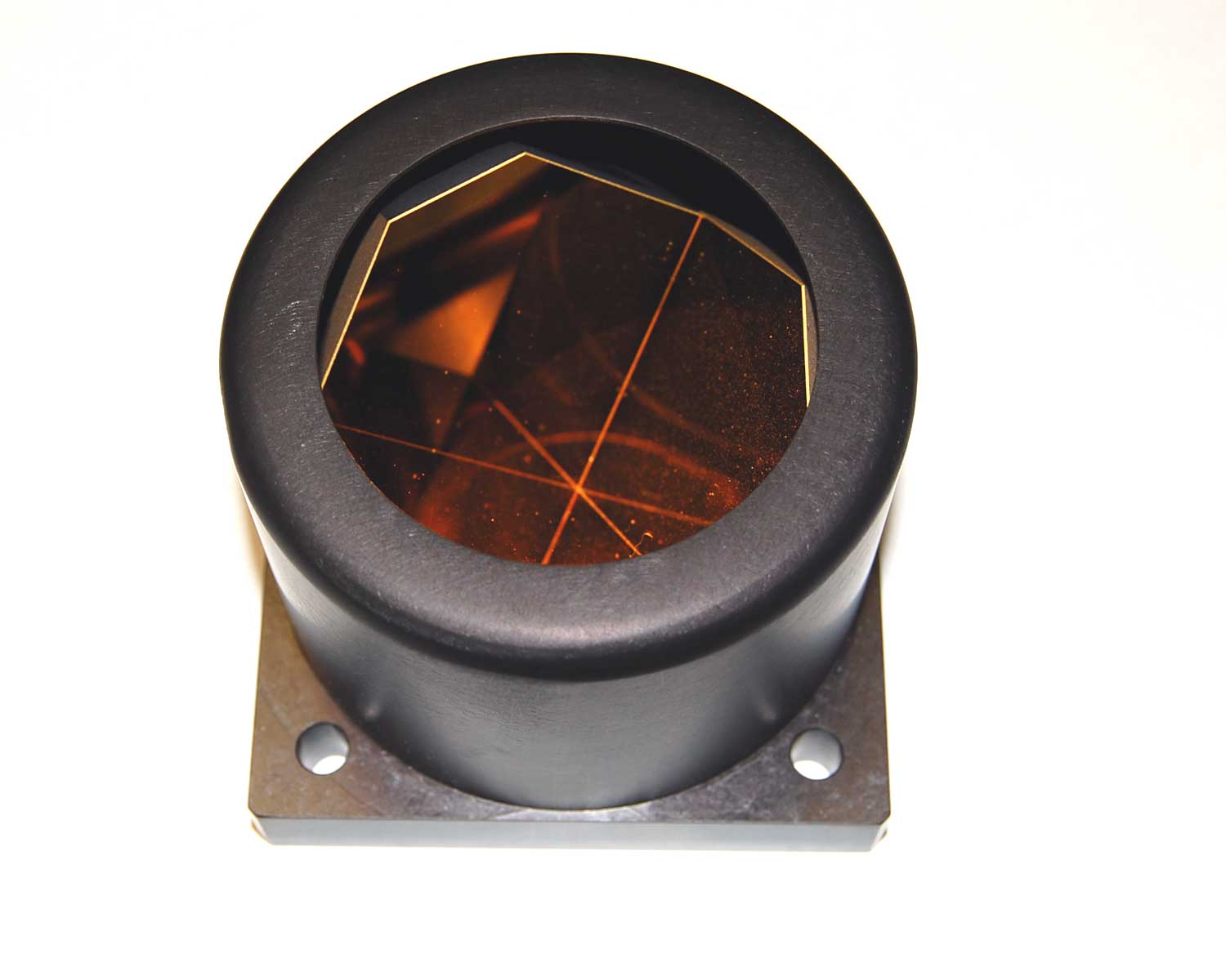
Surveying

[edit]
A typical surveying prism with back target

In surveying, a retroreflector—usually referred to as a prism—is normally attached on a surveying pole and is used as a target for distance measurement, for example, a total station. The instrument operator or robot aims a laser beam at the retroreflector. The instrument measures the propagation time of the light and converts it to a distance. Prisms are used with survey and 3D point monitoring systems to measure changes in horizontal and vertical position of a point. Two prisms may also serve as targets for angle measurements, using total stations or simpler theodolites; this usage, reminiscent of the heliotrope, does not involve retroreflection per se, it only requires visibility by means of any source of illumination (such as the sun) for direct sighting to the center of the target prism as seen from the optical instrument.

In space

[edit]

On the Moon

[edit]
The Apollo 11 Lunar Laser Ranging Experiment

Astronauts on the Apollo 11, 14, and 15 missions left retroreflectors on the Moon as part of the Lunar Laser Ranging Experiment. The Soviet Lunokhod 1 and Lunokhod 2 rovers also carried smaller arrays. Reflected signals were initially received from Lunokhod 1, but no return signals were detected from 1971 until 2010, at least in part due to some uncertainty in its location on the Moon. In 2010, it was found in Lunar Reconnaissance Orbiter photographs and the retroreflectors have been used again. Lunokhod 2's array continues to return signals to Earth.[5] Even under good viewing conditions, only a single reflected photon is received every few seconds. This makes the job of filtering laser-generated photons from naturally occurring photons challenging.[6]

Vikram lander of Chandrayaan-3 left Laser Retroreflector Array (LRA) instrument supplied by NASA's Goddard Space Flight Center as part of international collaboration with ISRO. On 12 December 2023, Lunar Reconnaissance Orbiter was successfully able to detect transmitted laser pulses from Vikram lander.[7]

On Mars

[edit]

A similar device, the Laser Retroreflector Array (LaRA), has been incorporated in the Mars Perseverance rover. The retroreflector was designed by the National Institute for Nuclear Physics of Italy, which built the instrument on behalf of the Italian Space Agency.

Mars Perseverance rover - LaRA - (artwork)

In satellites

[edit]

Many artificial satellites carry retroreflectors so they can be tracked from ground stations. Some satellites were built solely for laser ranging. LAGEOS, or Laser Geodynamics Satellites, are a series of scientific research satellites designed to provide an orbiting laser ranging benchmark for geodynamical studies of the Earth.[8] There are two LAGEOS spacecraft: LAGEOS-1[9] (launched in 1976), and LAGEOS-2 (launched in 1992). They use cube-corner retroreflectors made of fused silica glass. As of 2020, both LAGEOS spacecraft are still in service.[10] Three STARSHINE satellites equipped with retroreflectors were launched beginning in 1999. The LARES satellite was launched on February 13, 2012. (See also: List of laser ranging satellites.)

Other satellites include retroreflectors for orbit calibration[11] and orbit determination,[12] such as in satellite navigation (e.g., all Galileo satellites,[13] most GLONASS satellites,[14] IRNSS satellites,[15] BeiDou,[16] QZSS,[17] and two GPS satellites[18]) as well as in satellite gravimetry (GOCE[19]) satellite altimetry (e.g., TOPEX/Poseidon, Sentinel-3[20]). Retroreflectors can also be used for inter-satellite laser ranging instead of ground-tracking (e.g., GRACE-FO).[21]

The BLITS (Ball Lens In The Space) spherical retroreflector satellite was placed into orbit as part of a September 2009 Soyuz launch[22] by the Federal Space Agency of Russia with the assistance of the International Laser Ranging Service, an independent body originally organized by the International Association of Geodesy, the International Astronomical Union, and international committees.[23] The ILRS central bureau is located at the United States' Goddard Space Flight Center. The reflector, a type of Luneburg lens, was developed and manufactured by the Institute for Precision Instrument Engineering (IPIE) in Moscow. The mission was interrupted in 2013 after a collision with space debris.[24][25]

Free-space optical communication

[edit]

Modulated retroreflectors, in which the reflectance is changed over time by some means, are the subject of research and development for free-space optical communications networks. The basic concept of such systems is that a low-power remote system, such as a sensor mote, can receive an optical signal from a base station and reflect the modulated signal back to the base station. Since the base station supplies the optical power, this allows the remote system to communicate without excessive power consumption. Modulated retroreflectors also exist in the form of modulated phase-conjugate mirrors (PCMs). In the latter case, a "time-reversed" wave is generated by the PCM with temporal encoding of the phase-conjugate wave (see, e.g., SciAm, Oct. 1990, "The Photorefractive Effect," David M. Pepper, et al.).

Inexpensive corner-aiming retroreflectors are used in user-controlled technology as optical datalink devices. Aiming is done at night, and the necessary retroreflector area depends on aiming distance and ambient lighting from street lamps. The optical receiver itself behaves as a weak retroreflector because it contains a large, precisely focused lens that detects illuminated objects in its focal plane. This allows aiming without a retroreflector for short ranges.

Other uses

[edit]
Demonstration of retroreflective effect with camera flash

Retroreflectors are used in the following example applications:

  • In common (non-SLR) digital cameras, the sensor system is often retroreflective. Researchers have used this property to demonstrate a system to prevent unauthorized photographs by detecting digital cameras and beaming a highly focused beam of light into the lens.[26]
  • In movie screens to allow for high brilliance under dark conditions.[27]
  • Digital compositing programs and chroma key environments use retroreflection to replace traditional lit backdrops in composite work as they provide a more solid color without requiring that the backdrop be lit separately.[28]
  • In Longpath-DOAS systems retroreflectors are used to reflect the light emitted from a lightsource back into a telescope. It is then spectrally analyzed to obtain information about the trace gas content of the air between the telescope and the retro reflector.
  • Barcode labels can be printed on retroreflective material to increase the range of scanning up to 50 feet.[29]
  • In a form of 3D display; where a retro-reflective sheeting and a set of projectors is used to project stereoscopic images back to user's eye. The use of mobile projectors and positional tracking mounted on user's spectacles frame allows the illusion of a hologram to be created for computer generated imagery.[30][31][32]
  • Flashlight fish of the family Anomalopidae have natural retroreflectors. See tapetum lucidum.
  • High-visibility clothing, especially in the construction industry.

History

[edit]

Many prey and predator animals have naturally retroreflective eyes by having a reflective layer called the Tapetum lucidum behind the retina, since this doubles the light that their retina receives.

Double-ended cat's eye is Shaw's original design and marks road centre-line.

Inspired by the natural world, the inventor of road 'cat's eyes' was Percy Shaw of Boothtown, Halifax, West Yorkshire, England. When the tram-lines were removed in the nearby suburb of Ambler Thorn, he realised that he had been using the polished steel rails to navigate at night.[33] The name "cat's eye" comes from Shaw's inspiration for the device: the eyeshine reflecting from the eyes of a cat. In 1934, he patented his invention (patents Nos. 436,290 and 457,536), and on 15 March 1935, founded Reflecting Roadstuds Limited in Halifax to manufacture the items.[34][35] The name Catseye is their trademark.[36] The retroreflecting lens had been invented six years earlier for use in advertising signs by Richard Hollins Murray, an accountant from Herefordshire[37][38] and, as Shaw acknowledged, they had contributed to his idea.[33]

See also

[edit]

Notes

[edit]

References

[edit]
[edit]
Revisions and contributorsEdit on WikipediaRead on Wikipedia
from Grokipedia
A retroreflector is an optical device or surface that reflects incident light or other electromagnetic radiation directly back toward its source with minimal scattering, independent of the angle of incidence. This property arises from designs that utilize multiple internal reflections, such as corner cube prisms—formed by three mutually perpendicular reflective surfaces—or transparent microspheres that leverage refraction and total internal reflection to redirect light parallel to its incoming path. Common types include glass bead retroreflectors, which embed high-index spheres in a reflective backing for diffuse applications, and prismatic retroreflectors, which employ microscopic cube-corner arrays for higher efficiency and directional control. Retroreflectors operate on fundamental optical principles including specular reflection from mirrored surfaces and total internal reflection within dielectric materials, enabling them to function over wide angular ranges unlike conventional mirrors. Developed in the early 20th century, early forms used large glass spheres for cinema screens and signage, evolving in the 1930s–1970s through innovations like 3M's enclosed-lens sheeting and microprismatic materials to achieve retroreflectance efficiencies up to 50% or more. In practical use, they enhance visibility in low-light conditions; for instance, glass beads in road markings return headlights to drivers, reducing crash risks by improving nighttime detection distances to at least 300 feet under standard conditions. Notable applications span transportation, where retroreflective sheeting on signs and pavement meets federal standards for durability and brightness, to scientific endeavors like NASA's Apollo 11 lunar retroreflector array, which enables precise laser ranging to measure Earth-Moon distance variations down to millimeters. In space exploration, compact laser retroreflective arrays (LRAs) on missions such as Perseverance rover and upcoming Artemis landers facilitate accurate positioning, velocity tracking, and even potential communication without active power. Additional uses include surveying instruments, safety apparel, and interferometry in photonics, where their angle-independent performance minimizes alignment errors.

Types of Retroreflectors

Corner Reflectors

First described by August Beck in 1887 as the "tripelspiegel," corner reflectors, also known as corner cubes, are optical devices composed of three mutually perpendicular flat reflective surfaces that intersect to form a trihedral corner. These surfaces are typically fabricated from materials such as glass for solid designs, metal for durable coatings, or plastic for lightweight applications, with reflective layers applied to achieve high reflectivity across desired wavelengths. The structure was further analyzed by C. A. Duboc in his 1943 Ph.D. thesis at MIT. In operation, an incident ray enters the corner and undergoes a single reflection off each of the three surfaces, resulting in a total of three bounces that reverse the ray's direction exactly, returning it parallel to the incoming path toward the source. This retroreflection occurs regardless of the precise angle of incidence, as long as the ray strikes within the effective aperture and the incidence is within approximately ±30° of the cube's body diagonal. Ray tracing confirms that the sequence of reflections—reversible in nature—ensures the output direction opposes the input, independent of the entry point within the valid subarea. Variations of corner reflectors include solid designs, where a single block of transparent material like glass uses total internal reflection at the rear faces, and hollow open-frame configurations, which employ separate mirrors mounted at precise perpendicular angles without intervening media for reduced weight and chromatic effects. Larger aperture sizes minimize beam spread from diffraction, governed by the approximate angular spread θ ≈ λ / D, where λ represents the wavelength of light and D the effective diameter; smaller devices exhibit greater spreading, limiting long-range performance. These devices offer advantages such as structural simplicity, enabling low-cost fabrication through methods like epoxy bonding or mandrel templating, and high efficiency for visible light with minimal power requirements due to their passive nature. However, limitations include a restricted field of view beyond ±30° where retroreflection efficiency drops, and sensitivity to incident light polarization, which can alter reflection properties in uncoated or TIR-based variants. A notable application is in radar corner reflectors for maritime navigation aids, such as those mounted on buoys and small boats, where their broad angular response—up to 90° in some configurations—provides strong, omnidirectional echoes to enhance vessel detectability.

Cat's-Eye Reflectors

Cat's-eye retroreflectors utilize refractive optics to direct incident light back toward its source, making them ideal for flexible sheet materials that enhance nighttime visibility in traffic signs, road markings, and safety apparel. These devices mimic the reflective properties of a cat's eye through either glass microspheres or prismatic elements, providing efficient retroreflection over broad angles without requiring discrete mirror structures. Developed primarily for highway and signage applications, they offer a cost-effective alternative to bulkier retroreflective systems by integrating optical elements into thin, durable films. The primary design types include glass bead-embedded sheets and microprism arrays. Glass bead sheets incorporate numerous small, transparent glass spheres partially or fully embedded in a polymer substrate; exposed-lens variants leave the beads protruding from the surface for direct light entry, while enclosed-lens designs seal the beads beneath a protective transparent overlay to shield against environmental damage. Microprism arrays consist of precisely molded, microscopic tetrahedral prisms formed in transparent plastic sheets, creating a dense pattern of angular facets that function collectively as retroreflective units. In operation, incident light enters the front face of a glass bead or prism, refracts toward the rear surface, undergoes total internal reflection at the curved bead interface or angled prism faces, and then refracts outward parallel to the incoming direction, ensuring the reflected beam returns efficiently to the observer. This process relies on the geometry of the elements to focus and redirect light with minimal divergence, achieving retroreflection even at oblique incidence angles. Unlike discrete corner reflectors that employ mirrored surfaces, cat's-eye designs adapt the retroreflection principle for planar, conformable sheets suitable for large-area applications. Performance is quantified by the coefficient of luminous intensity (cd/lx/m²), which measures retroreflected light per unit area and incident illuminance; engineering-grade glass bead sheeting typically achieves 70–250 cd/lx/m², while high-intensity prismatic variants exceed 500 cd/lx/m² under standard observation and entrance angles. These materials support in-plane angular ranges up to 360 degrees, enabling omnidirectional visibility for applications like circular signs or curved surfaces. Construction involves high-clarity glass spheres for bead types and transparent polymers like polycarbonate or polyvinyl chloride for microprism molding, with metallic aluminum or silver coatings applied to prism bases or bead rears to enhance reflection efficiency. Over time, UV exposure accelerates polymer chain scission and yellowing, reducing transparency and reflectivity by up to 50% after several years outdoors, while soiling from atmospheric dust and pollutants can diminish performance by 20–30% through light scattering and absorption until cleaned. Pioneered by 3M engineers in the 1930s, glass bead retroreflective sheeting emerged as a breakthrough for highway signage, with early prototypes tested on roads by 1939 following patents filed in 1937. Microprism technology advanced in the mid-20th century, with key developments including Reflexite's prismatic sheeting in the 1960s and subsequent 3M innovations like high-intensity prismatic films in the 1970s.

Phase-Conjugate Retroreflectors

Phase-conjugate retroreflectors represent an active class of retroreflective devices that leverage nonlinear optical phase conjugation to generate a precise time-reversed replica of an incident wavefront, enabling correction of distortions in coherent light beams. Unlike passive retroreflectors, which rely on geometric reflection for ray reversal, these systems employ nonlinear interactions to conjugate the phase of the input wave, effectively undoing propagation-induced aberrations such as those from atmospheric turbulence. This capability makes them particularly valuable in laser-based applications requiring high-fidelity beam return. The core principle involves degenerate four-wave mixing (DFWM) in a nonlinear medium, where two strong counterpropagating pump beams and a weaker probe beam (the incident signal) interact to produce the phase-conjugate output beam. In photorefractive crystals like barium titanate (BaTiO₃) or liquids such as carbon disulfide (CS₂), the nonlinear susceptibility creates dynamic holographic gratings that diffract the probe into the conjugate wave. The phase relationship is given by ϕconj=ϕinc\phi_{\text{conj}} = -\phi_{\text{inc}}, where ϕconj\phi_{\text{conj}} is the phase of the conjugate wave and ϕinc\phi_{\text{inc}} is the incident phase, resulting in exact wavefront reversal. This process was theoretically formalized in seminal work on DFWM by Hellwarth in 1977, building on earlier demonstrations of phase conjugation via stimulated Brillouin scattering by Zel'dovich et al. in 1972. In practical setups for laser systems, the phase-conjugate retroreflector corrects atmospheric distortions by reflecting the beam such that aberrations accumulated on the outbound path are precisely canceled upon return, restoring the original wavefront shape at the source. Efficiency varies with the nonlinear gain of the medium; for instance, stimulated Brillouin scattering configurations in gases or liquids can yield phase-conjugate reflectivities exceeding 100%, allowing amplification alongside conjugation. These devices offer key advantages, including automatic alignment over extended distances without mechanical adjustment and robust handling of complex aberrations, which has driven their development since the 1970s for adaptive optics in high-power lasers. However, they necessitate a coherent laser source and substantial pump power—often in the kilowatt range—to initiate the nonlinear process, restricting deployment to controlled, laser-centric environments.

Principles of Operation

Geometrical Reflection in Linear Retroreflectors

Linear retroreflectors, such as corner cubes, achieve retroreflection through successive specular reflections off planar surfaces arranged in a specific geometry, directing incident rays back parallel to their incoming direction. In a corner reflector, the three reflecting faces are mutually perpendicular, forming a trihedral configuration. An incoming ray strikes the first face, reflects according to the law of reflection—where the angle of incidence equals the angle of reflection (θ_i = θ_r)—and proceeds to the second face, undergoing another identical reflection. This process repeats for the third face, resulting in the ray's direction being exactly reversed after three bounces, independent of the initial incidence angle within the device's operational limits. The mathematical foundation for each reflection can be described using vector optics. For an incident ray direction vector I\mathbf{I} (unit vector) and a unit surface normal n\mathbf{n}, the reflected ray direction R\mathbf{R} is given by the formula: R=I2(nI)n\mathbf{R} = \mathbf{I} - 2 (\mathbf{n} \cdot \mathbf{I}) \mathbf{n} Applying this successively to the three orthogonal normals of the corner faces effectively inverts the incident vector, R=I\mathbf{R} = -\mathbf{I}, ensuring perfect retroreflection for rays entering the aperture. This geometric invariance holds for both hollow (air-filled, metallic-coated) and solid (refractive material with total internal reflection) designs, though the latter incorporates refraction at the entry/exit face via Snell's law for path adjustment. Imperfections in alignment introduce small deviations in the output ray direction. For a dihedral angle error dd, the angular deviation δ\delta of the reflected beam from the ideal retrodirection is approximately δ2d\delta \approx 2d. Such tolerances are critical in precision applications, where dihedral errors on the order of arcseconds can shift the beam by microradians, reducing return efficiency. The field of view for corner cubes is typically around 90 degrees, allowing retroreflection over a wide angular range before vignetting or efficiency drop-off occurs due to rays missing subsequent faces. Beam divergence in the return path arises from the finite aperture size, governed by diffraction limits; for a cube edge length aa, the divergence angle is roughly θλ/a\theta \approx \lambda / a, where λ\lambda is the wavelength, concentrating the retroreflected energy into a narrow cone aligned with the source. Polarization effects emerge from the coatings on the reflecting surfaces. Metallic coatings (e.g., aluminum or gold) exhibit diattenuation—differential transmission or reflection based on polarization state—typically lower than in dielectric coatings, preserving incident polarization more uniformly across angles but introducing slight retardance. Dielectric coatings, often used for total internal reflection in solid prisms, can amplify diattenuation due to Fresnel coefficients varying with s- and p-polarizations, potentially reducing the effective retroreflected intensity by up to a factor of 4 for certain orientations. This geometrical framework extends briefly to cat's-eye retroreflectors, where refractive elements focus the ray onto a curved mirror for similar reversal, though without the multi-bounce planar reflections.

Total Internal Reflection Mechanisms

In cat's-eye retroreflectors, particularly those utilizing glass beads, incident light refracts into the spherical bead due to the difference in refractive indices between the surrounding medium and the glass, which typically has an index of 1.5 to 1.9. The refracted ray propagates toward the rear surface of the bead, where it reflects—either by total internal reflection if interfacing with air or a lower-index medium, or more commonly by a reflective backing or coating—redirecting the ray back through the bead. The returning ray then refracts out of the front surface parallel to the original incident direction, resulting in retroreflection toward the source. The critical angle for TIR is θc=arcsin(nmedium/nbead)\theta_c = \arcsin(n_\text{medium} / n_\text{bead}) when applicable. This mechanism relies on the spherical geometry to focus light near the rear for efficient reflection without additional mirrors in simple designs. Microprism retroreflectors employ arrays of precisely molded triangular prisms, each featuring a 90-degree apex angle to facilitate retroreflection through total internal reflection. Incident light enters the prism face and undergoes two successive internal reflections off the angled sides, which are oriented to reverse the ray's direction by 180 degrees. This prismatic structure traps light within the high-index material (typically optical glass or polymer with n ≈ 1.5), ensuring the output beam remains parallel to the input regardless of minor misalignments, similar to the geometric paths in corner reflectors but emphasizing refractive confinement. Both glass bead and microprism designs experience losses primarily from Fresnel reflections at material interfaces, quantified by the amplitude reflection coefficient r = |(n_1 - n_2)/(n_1 + n_2)| for normal incidence, which reduces the transmitted intensity by up to 4-8% per surface depending on index mismatch. Dispersion in the glass or polymer introduces color dependence, as the refractive index varies with wavelength, causing shorter wavelengths (e.g., blue) to reflect more efficiently than longer ones (e.g., red) and potentially shifting the retroreflected spectrum. These mechanisms enable broader angular performance compared to corner reflectors, maintaining effective retroreflection up to 40 degrees off-axis before significant degradation. Encapsulated glass bead configurations enhance durability by sealing the beads within a polymer matrix or honeycomb structure, preventing moisture ingress that could degrade the air-glass interface essential for total internal reflection and extend service life in harsh environments.

Nonlinear Optical Processes

Nonlinear optical processes in retroreflectors enable phase conjugation through parametric interactions, generating a time-reversed wavefront that propagates back along the incident beam path, distinct from passive linear reflection by actively compensating distortions via nonlinear susceptibility. This process relies on third-order nonlinearities, where intense coherent light induces refractive index or absorption gratings in the medium, facilitating wave mixing. In phase-conjugate retroreflectors, a signal wave interacts with pump waves to produce a conjugate wave that corrects aberrations encountered during propagation. The core mechanism is four-wave mixing (FWM), involving two strong pump waves and a weak signal wave to generate the phase-conjugate wave. In degenerate FWM, the pumps operate at the same frequency as the signal, while non-degenerate FWM uses distinct frequencies for the pumps to enable frequency shifts, such as Doppler compensation in dynamic systems. Phase matching ensures efficient energy transfer, governed by the wavevector relation kconj=kp1+kp2ksig\mathbf{k}_{\text{conj}} = \mathbf{k}_{\text{p1}} + \mathbf{k}_{\text{p2}} - \mathbf{k}_{\text{sig}}, where kconj\mathbf{k}_{\text{conj}}, kp1\mathbf{k}_{\text{p1}}, kp2\mathbf{k}_{\text{p2}}, and ksig\mathbf{k}_{\text{sig}} are the wavevectors of the conjugate, pumps, and signal, respectively. Suitable media include Kerr-effect liquids like carbon disulfide (CS₂), which exhibit fast electronic nonlinearities; semiconductors such as gallium arsenide (GaAs) near band edges for resonant enhancement; and optical fibers, where multimode waveguides filled with CS₂ support extended interaction lengths. The conjugate wave gain follows G=exp(gL)G = \exp(gL), with gg as the nonlinear gain coefficient and LL the interaction length, enabling amplification up to 20 times the input intensity under optimal conditions like αL=7\alpha L = 7 and pump intensity 25 times saturation. These processes excel in distortion correction, reversing phase aberrations from sources like atmospheric turbulence modeled by the Kolmogorov spectrum, where the phase structure function Dϕ(r)=6.88(r/r0)5/3D_\phi(r) = 6.88 (r / r_0)^{5/3} quantifies wavefront irregularities, with r0r_0 the Fried parameter. For instance, stimulated Brillouin scattering-enhanced FWM in CS₂ has restored beams to near-diffraction-limited quality (0.44 mrad divergence from 6.6 mrad aberrated), countering turbulence-induced scintillation over long paths. However, operation requires intense coherent illumination exceeding thresholds, such as ~800 MW/cm² for SBS in CS₂ liquids or ~1-10 kW/cm² for resonant FWM in dye solutions, with decoherence from thermal noise limiting effective range in non-degenerate configurations. Hybrid systems may integrate these with linear retroreflectors for initial beam directionality, but the nonlinear stage provides the conjugation fidelity.

Applications

Traffic and Road Safety

Retroreflectors play a crucial role in traffic and road safety by enhancing visibility of infrastructure elements during low-light conditions, primarily through their use in road markings, traffic signs, and vehicle components. These devices, often based on cat's-eye principles, return incident light from vehicle headlights directly to the driver, improving detection distances and reducing the likelihood of collisions. In road markings and signs, microprism sheeting conforming to ASTM D4956 standards is commonly employed, with Type XI high-intensity prismatic sheeting offering superior performance. This material achieves retroreflectivity greater than 250 cd/lx/m² at a 0.2° observation angle, ensuring clear visibility at typical driving distances. Vehicle applications further leverage retroreflective materials to boost safety, such as in taillights and license plates, where beaded films reflect light effectively from approaching vehicles. For bicycles, reflectors mounted on pedals and chainstays meet federal standards under 16 CFR § 1512.16, providing recognition under motor vehicle headlamp illumination to alert drivers to cyclists' presence. Performance standards for these materials include specific entrance angularity tolerances, such as 0.33° observation and -0.2° entrance angles to simulate headlight illumination, ensuring consistent reflectivity across various approach geometries. Additionally, high-quality sheeting demonstrates fade resistance, maintaining effectiveness over 10 years through UV and weather-resistant formulations. Studies by the Federal Highway Administration (FHWA) indicate that retroreflective elements in signs and pavement markings can reduce nighttime crashes, highlighting their impact on low-light crash rates. Edge-lit designs for dynamic signs further enhance this by combining retroreflectivity with illumination for variable messaging. Post-2020 developments include LED-integrated retroreflective panels for smart highways, as seen in FHWA's 2022 final rule mandating higher retroreflectivity for pavement markings to improve visibility in dark conditions, integrating with emerging intelligent transportation systems. Retroreflectors play a critical role in enhancing personal safety through portable and wearable devices that improve visibility in low-light conditions. Reflective vests and running gear incorporating 3M Scotchlite materials provide 360-degree visibility, allowing users such as pedestrians, joggers, and cyclists to be detected by vehicle headlights. These materials, based on microprismatic sheeting derived from cat's-eye designs, ensure light is directed back to the source regardless of angle, making them essential for nighttime activities. Cyclist ankle clips and armbands with similar retroreflective strips further aid in signaling movement, reducing collision risks in urban environments. In maritime applications, retroreflectors are integrated into life jackets, vests, and buoys to facilitate detection during emergencies. SOLAS-compliant life jackets feature retroreflective tape that enhances visual identification by search vessels or aircraft, meeting International Maritime Organization standards for luminous intensity. Buoys and life rafts often employ corner reflectors to boost radar cross-section (RCS), with designs achieving at least 7.5 m² in X-band per SOLAS standards to ensure detection even in adverse weather. These passive devices reflect radar signals directly back to the interrogating source, complementing active beacons for comprehensive search and rescue (SAR) operations. Aviation and broader emergency equipment leverage retroreflectors for rapid location in distress scenarios, including fire response and aerial rescues. Firefighter gear incorporates retroreflective stripes compliant with NFPA 1971 standards to maintain visibility amid smoke and flames during low-light operations. Rescue beacons and personal locator beacons (PLBs) for aviation emergencies, such as those used in crash survivable modules, often include retroreflective panels to aid visual confirmation once GPS signals pinpoint the location. The integration of retroreflective elements with GPS-enabled PLBs allows for hybrid passive-active systems that improve detection in remote or obscured areas. The use of retroreflectors in navigation and emergency contexts traces to 20th-century maritime innovations, with SOLAS regulations in 1914 laying groundwork for improved distress signaling. Following the 1912 disaster, which highlighted visibility failures in rescue efforts, subsequent standards evolved to mandate reflective materials. Post-2000 amendments, such as IMO Resolution MSC.97(73) in 2000, include requirements for retroreflective material on lifesaving appliances in high-speed craft for enhanced detection. These developments addressed gaps in earlier systems by combining retroreflection with emerging technologies like GPS for precise, multi-modal emergency response.

Geodetic Surveying

In geodetic surveying, corner cube retroreflectors, typically in the form of prisms, are integral to electronic distance measurement (EDM) systems within total stations for precise terrestrial ranging. These devices reflect laser beams back to the instrument along a parallel path, enabling accurate distance calculations over kilometers with minimal beam divergence. High-end systems achieve accuracies better than 1 mm + 1 ppm (parts per million), equivalent to less than 1 mm error per kilometer, making them essential for establishing control points in mapping and deformation studies. Prism constants, or offset values, account for the physical displacement between the prism's mounting point and its effective optical center, ensuring centering accuracy during measurements. Common offsets range from -30 mm to 0 mm, depending on the prism design and instrument wavelength, and must be calibrated to avoid systematic errors in distance computations. These retroreflectors augment global positioning system (GPS) networks by providing high-precision local ties at permanent stations, such as those in the UNAVCO Plate Boundary Observatory (PBO), where they support crustal deformation monitoring through repeated EDM observations alongside GNSS data. Retroreflectors also play a key role in very long baseline interferometry (VLBI) for geodetic baseline calibration via local tie surveys, where total stations with prism targets measure sub-millimeter offsets between antenna reference points and monument markers. The ranging resolution follows the equation Δd=cΔt2\Delta d = \frac{c \Delta t}{2}, where cc is the speed of light and Δt\Delta t is the round-trip time-of-flight, with retroreflectors enhancing precision by minimizing beam spread and signal loss over short baselines up to 200 m. All-weather operability allows continuous data collection in varied conditions, though measurements require corrections for atmospheric refraction, which can introduce errors up to several millimeters per kilometer due to variations in air density and temperature. Recent advancements include drone-mounted retroreflectors for urban surveying, enabling access to inaccessible areas like building facades or dense infrastructure. By attaching prisms to unmanned aerial vehicles (UAVs) and tracking them with ground-based total stations, surveyors achieve positional accuracies of 10-20 mm in real-time trajectory monitoring, addressing gaps in traditional pole-based methods for complex environments as demonstrated in studies from 2021-2023. This technology, evolving through 2025, supports efficient 3D mapping in cities while maintaining geodetic standards.

Space Exploration

Retroreflectors have played a pivotal role in space exploration, particularly in precise distance measurements and orbit determination for celestial bodies. In lunar science, the Lunar Laser Ranging (LLR) experiment utilizes retroreflector arrays deployed on the Moon's surface to reflect laser pulses from Earth-based observatories, enabling millimeter-level accuracy in measuring the Earth-Moon distance. These arrays, consisting of corner-cube prisms, allow for ongoing tests of general relativity, including the Shapiro time delay, where laser signals passing near the Sun experience gravitational redshift and delay. The Apollo missions deployed four such arrays during Apollo 11, 14, 15, and 16 between 1969 and 1972. Each array features fused-silica corner cubes arranged in panels approximately 46 cm square for Apollo 11 and 14 (with 100 cubes each) and larger configurations for Apollo 15 and 16 (300 cubes each), achieving range accuracies of about 1 cm root-mean-square. Additionally, the Soviet Lunokhod 1 and 2 rovers, launched in 1970 and 1973, carried French-built retroreflectors with 14 corner cubes each, expanding the network for LLR observations. Ongoing LLR data from these arrays reveal the Moon's recession from Earth at a rate of 3.8 cm per year, driven by tidal interactions. On Mars, the Laser Retroreflector for InSight (LaRRI), deployed by NASA's InSight lander in 2018, consists of an array of eight corner cubes designed for laser ranging from future orbiting spacecraft to refine planetary orbits and support navigation. Looking ahead, NASA's Next Generation Lunar Retroreflector (NGLR) initiative aims to deploy advanced single large-aperture corner cubes via Commercial Lunar Payload Services missions starting in 2025; NGLR-1 was successfully deployed in early 2025 via the Blue Ghost mission, with initial laser ranging achieved in March 2025, enhancing LLR precision for Artemis program orbit determination and gravitational studies. Satellite-based retroreflectors, such as those on the Laser Geodynamics Satellites (LAGEOS-1 and -2), launched in 1976 and 1992, feature 426 cube-corner retroreflectors each, enabling satellite laser ranging for high-precision mapping of Earth's gravity field and tectonic plate motions. These passive systems support drag-free and low-drag orbit analyses in missions like GRACE, contributing to global geophysical models. Efforts to expand LLR coverage include planned far-side deployments, such as the MoonLIGHT retroreflector proposed for high-accuracy relativity tests and the LaRA2 array slated for 2026 via ispace's Mission 3, addressing gaps in lunar network geometry. However, retroreflectors face challenges like thermal expansion from extreme lunar temperature swings (-173°C to 127°C), which induces lensing effects reducing signal return, and micrometeorite impacts causing surface degradation over decades. Dust accumulation further attenuates returns, as evidenced by declining efficiencies in Apollo arrays.

Optical Communications

In free-space optical communication systems, corner cube retroreflectors serve as passive elements for initial pointing acquisition and tracking in satellite-to-ground links, reflecting an interrogating laser beam back to the originating terminal to enable precise alignment without active onboard transmitters. These devices facilitate bidirectional laser links by providing a stable return signal for acquisition, tracking, and pointing (ATP) mechanisms, particularly in scenarios where the remote terminal has limited power or size constraints. For instance, in NASA's Lunar Laser Communication Demonstration (LLCD) aboard the LADEE spacecraft in 2013, retroreflectors supported acquisition processes as precursors to active ranging techniques used in space exploration. Modulating retroreflectors (MRRs) extend this capability by integrating an optical modulator, such as liquid crystal displays (LCDs) or micro-electro-mechanical systems (MEMS), directly with a corner cube array, allowing the remote terminal to encode data onto the reflected interrogating beam for low-power uplink communication. This asymmetric architecture shifts the high-power laser and receiver complexity to the interrogator side, enabling data rates exceeding 1 kbps over distances greater than 100 km, with demonstrations achieving up to 10 Mbps at 16 km in ground tests and potential for 12 Mbps at 400 km in low Earth orbit simulations. MRRs are particularly suited for resource-constrained platforms, consuming less than one-tenth the power of traditional RF systems while avoiding spectrum allocation issues. Phase-conjugate retroreflectors incorporate nonlinear optical processes to create adaptive links that correct for atmospheric scintillation and wavefront distortions in turbulent channels, effectively reversing phase aberrations through optical phase conjugation (OPC) for improved signal fidelity over long paths. The link budget for such systems can be approximated by the received power equation: Pr=PtAr4πR2ηretroP_r = P_t \frac{A_r}{4\pi R^2} \eta_{retro} where PrP_r is the received power, PtP_t is the transmitted power, ArA_r is the receiver aperture area, RR is the link distance, and ηretro\eta_{retro} accounts for the retroreflector's efficiency, including modulation and atmospheric losses. This approach has been demonstrated to mitigate fading in free-space links, enhancing reliability for high-speed MRR variants. MRRs find applications in military drone communications for secure, low-probability-of-intercept uplinks and in deep-space probes for efficient data return from power-limited spacecraft. Recent 2024 demonstrations highlight MRR integration on CubeSats for high-speed downlinks, optimizing acquisition and positioning with minimal size, weight, and power (SWaP). A key advantage is the elimination of an onboard laser at the remote terminal, reducing mass and energy demands while enabling wide field-of-view operation.

Scientific and Industrial Uses

Retroreflectors play a critical role in lidar-based simultaneous localization and mapping (SLAM) systems for autonomous vehicles, where they serve as high-fidelity calibration targets to enhance sensor accuracy and environmental perception. In mobile robotics and self-driving platforms, such as those developed by Waymo in the 2020s, retroreflective markers enable precise alignment of lidar sensors by reflecting laser beams directly back to the source, minimizing divergence and improving pose estimation during mapping and navigation tasks. This approach achieves calibration accuracies below 1 cm, even in dynamic environments, by leveraging the corner-cube geometry to maintain beam integrity over distances relevant to urban driving. In medical applications, retroreflectors facilitate precise optical alignment in endoscopy procedures and interferometric quantum sensors. For endoscopy, they are integrated into all-reflective optical systems within tethered capsule endoscopes to ensure stable beam paths and reduce misalignment errors during multimodal imaging, such as optical coherence tomography. In quantum sensing, retroreflectors form key components in cold atom interferometers, where they reflect atomic wave packets with minimal phase distortion to enable high-sensitivity measurements of inertial forces, as demonstrated in hybrid optomechanical designs that combine retroreflection with quantum entanglement for enhanced precision. Evaluation of retroreflector optical properties, including intensity distribution and interference patterns, confirms their suitability for quantum absolute gravimeters, achieving reflection efficiencies that support sub-micrometer resolution in interferometric setups. Industrial uses of retroreflectors extend to machine vision for automated part inspection and holography setups requiring phase-conjugate beam cleanup. In manufacturing, laser trackers equipped with retroreflectors enable non-contact measurement of large components, such as aircraft fuselages, by positioning the reflector on the target surface to reflect the tracking beam back with sub-millimeter accuracy, facilitating real-time defect detection and dimensional verification. Selective retroreflectors also serve as invisible markers for machine vision systems, providing omnidirectional reflection in specific wavelengths to identify parts without human visibility, ideal for high-speed assembly lines. In holography, arrays of corner-cube retroreflectors approximate phase conjugators by reversing wavefront distortions, enabling cleanup of aberrated beams in interferometric recording and improving image resolution through nonlinear optical processes. Retroreflectors are integral to beam steering in gravitational wave detectors like LIGO, where retroreflected beams from reference flats aid in precise alignment of interferometer arms during initial setup and maintenance, ensuring the laser paths remain collinear to detect minute spacetime distortions. Emerging hollow retroreflector designs, prized for their lightweight construction, are increasingly adopted in aerospace applications to reduce payload mass in satellite ranging systems, with the global market projected to grow from USD 500 million in 2024 to USD 1.2 billion by 2033 at a CAGR of 10.2%, driven by demand for durable, low-weight optics in space exploration. In augmented and virtual reality (AR/VR), retroreflective markers enable low-power 3D tracking for headsets, supporting gaze estimation and interaction by reflecting infrared light back to onboard sensors, thus integrating seamlessly with eye-tracking modules to enhance user immersion without excessive battery drain.

History

Early Concepts and Inventions

The phenomenon of retroreflection, where light is reflected back toward its source, has natural precursors in certain minerals. Chrysoberyl, a beryllium aluminate mineral, exhibits the cat's-eye effect due to parallel fibrous inclusions that cause light to return along the incident path, mimicking retroreflection. This variety was first identified as a distinct mineral in the late 18th century, with the chatoyant form gaining popularity in jewelry by the 19th century for its luminous band of light. In the 19th century, advancements in optical engineering laid conceptual groundwork for artificial retroreflectors through catadioptric systems, which combined refraction and reflection to direct light efficiently. Augustin-Jean Fresnel developed these for lighthouses starting in the 1820s, using prisms and mirrors to project beams over long distances, though primarily for outward projection rather than return to the source. Early parabolic metal reflectors, introduced in lighthouses around 1777, further explored reflection principles but lacked the precise angular return of true retroreflection. The rise of the automobile in the early 20th century, with U.S. vehicle registrations surging from 8 million in 1920 to over 23 million by 1929, spurred practical inventions for road safety amid increasing nighttime travel. German inventor Rudolf Straubel received the first known patent for a reflector device in 1906, using glass spheres embedded in surfaces to enhance visibility. In 1926, American inventor J. Cass Stimson patented an array of cube-corner elements, forming the basis for modern corner-cube retroreflectors by bouncing light between three perpendicular surfaces. Driven by the same automotive boom and emerging aviation demands for airfield markers, 3M Company developed Scotchlite reflective sheeting in the late 1930s, incorporating glass beads to achieve retroreflection for highway signs and markings. Commercially introduced in 1938, it marked a key milestone in beaded retroreflectors, enabling painted lines and signs to remain visible from vehicle headlights without external power. At this stage, retroreflectors relied solely on geometric optics, with no nonlinear optical processes involved.

20th-Century Developments

Following World War II, retroreflector technology advanced significantly in materials and applications. In the 1940s, military engineers developed radar corner reflectors, consisting of mutually perpendicular metal plates arranged in a trihedral configuration, to enhance the radar visibility of ships and aircraft for identification and navigation purposes during naval operations. These devices, first deployed in wartime fleets, reflected radar waves back to their source with high efficiency, improving detection ranges by factors of up to 100 compared to non-reflective surfaces. By the 1950s, commercial innovations focused on optical retroreflectors for civilian use. In the 1960s, Reflexite introduced microprism retroreflective sheeting, utilizing arrays of tiny corner-cube prisms molded into flexible sheets, which provided superior brightness and durability over earlier glass-bead technologies for highway signage and markings. This development enabled sheeting with retroreflection coefficients exceeding 1000 cd/lx/m² at wide entrance angles, revolutionizing nighttime visibility. 3M later developed their prismatic sheeting in 1989. The Space Race catalyzed major milestones in precision retroreflector deployment. In 1969, the Apollo 11 mission placed the Lunar Laser Ranging Retroreflector (LRRR) on the Moon's surface, a panel of 100 fused-silica corner cubes designed and built by U.S. scientists at the University of Maryland, allowing ground-based lasers to measure Earth-Moon distance with millimeter accuracy. The Soviet Lunokhod 1 rover followed in 1970, carrying a similar French-supplied retroreflector array that enabled several laser ranging sessions in 1970 and additional ones after rediscovery in 2010, contributing to studies of lunar orbit perturbations. In 1976, NASA launched the Laser Geodynamics Satellite (LAGEOS), featuring a dense aluminum-coated retroreflector array of 426 cubes, which has since provided data for tectonic plate motion studies with sub-centimeter precision. Optical research progressed with theoretical and experimental breakthroughs in phase conjugation, a nonlinear process enabling perfect retroreflection of distorted wavefronts. Soviet physicist Yakov Zel'dovich proposed the foundational theory in the mid-1960s, describing how stimulated Brillouin scattering could reverse phase fronts in media like liquids or gases. Laboratory demonstrations emerged in the 1970s, with the first optical phase conjugator using degenerate four-wave mixing in atomic vapors reported in 1974, achieving conjugation fidelities over 90% for correcting atmospheric distortions. Standardization efforts in the 1970s and 1980s formalized retroreflector performance metrics. The International Commission on Illumination (CIE) published Publication 54 in 1982, defining measurement geometries and coefficients for retroreflective sheeting used in traffic control devices. Concurrently, ASTM International developed standards like D4956 in 1989, specifying minimum retroreflectivity levels (e.g., 150 cd/lx/m² for white sheeting) to ensure compliance in road safety applications. These standards underpinned mandates, such as the U.S. Federal Highway Administration's 1970s requirements for retroreflective signage on interstates, reducing nighttime accident rates by enhancing visibility distances to over 300 meters. In the 1980s, concepts for modulating retroreflectors emerged for communication systems, where passive arrays modulated incident signals via mechanical or electro-optic means to enable bidirectional laser links without onboard power. Early lidar applications also leveraged retroreflectors, with systems in the 1970s using them as calibration targets for atmospheric profiling, achieving range resolutions below 1 meter in field tests.

Recent Advancements and Future Prospects

In the 2000s, the U.S. Defense Advanced Research Projects Agency (DARPA) supported the development of modulating retroreflectors (MRRs) for unmanned aerial vehicles (UAVs), enabling low-power, high-data-rate optical communications by combining corner-cube retroreflectors with electro-optic modulators to reflect and encode laser signals from ground stations. These systems addressed payload constraints on small platforms, achieving data rates up to 10 Mbps in laboratory tests and over 400 Kbps during UAV flights. Building on this, MRR technology advanced through the 2010s and 2020s for free-space optical links, with demonstrations supporting satellite-to-ground downlinks at rates exceeding 1 Mbps while minimizing onboard power requirements. A notable milestone occurred in 2018 with the deployment of the Laser Retroreflector for InSight (LaRRI) on NASA's InSight Mars lander, the first operational retroreflector on Mars, designed as a lightweight array of eight corner cubes to enable precise ranging from Earth or orbiting spacecraft for geodetic measurements. Post-Apollo efforts to revive lunar retroreflector networks gained momentum in the 2020s, addressing the degradation of original Apollo arrays due to lunar librations and dust accumulation. The Next Generation Lunar Retroreflector (NGLR), developed by the University of Maryland for NASA's Artemis program, features a compact array of four large-aperture corner cubes optimized for sub-millimeter precision ranging; NGLR-1 was deployed on the Moon via Firefly Aerospace's Blue Ghost lander in March 2025 as part of the Commercial Lunar Payload Services initiative, with initial laser ranging successfully performed by NASA's Lunar Orbiter Laser Altimeter (LOLA) in early 2025. Complementing this, the MoonLIGHT retroreflector, a collaboration between NASA and the Italian Space Agency, targets enhanced general relativity tests through improved signal return efficiency. For the lunar far side, the Laser Retroreflector Array 2 (LaRA2), a palm-sized dome-shaped instrument from the Italian Space Agency, is scheduled for deployment on ispace's APEX 1.0 lander in 2026 at the Schrödinger Basin, enabling long-term laser ranging observations to map the far-side surface and support navigation for future missions. Technological improvements in retroreflector design have focused on lightweight, high-performance materials for space applications. In 2024, research advanced flat retroreflective foils and arrays for CubeSats, offering seamless integration with low-Earth orbit satellites for laser ranging without protruding structures, achieving diffuse reflection efficiencies suitable for small payloads. Hollow retroreflectors, constructed from three orthogonal flat mirrors rather than solid prisms, have emerged as a mass-efficient alternative for satellites, reducing weight by up to 50% while maintaining optical fidelity; the global market for these devices, valued at approximately $78 million in 2023, is projected to grow at a 7.5% CAGR through 2030, driven by demand in satellite constellations. Advancements in nanostructured retroreflective sheeting, incorporating microprism arrays on flexible substrates, have enhanced brightness for terrestrial and aerospace uses, though specific quantitative gains vary by application. Looking ahead, retroreflectors are poised for integration in emerging technologies, including modulating variants for quantum-enhanced laser ranging to achieve picometer precision in gravitational tests, building on MRR designs for CubeSat downlinks. In optical communications, retroreflectors may support 6G networks through free-space links for low-latency data transfer in urban and space environments. Additionally, arrays of retroreflectors on satellite constellations could enable precise orbit determination for climate monitoring missions, facilitating millimeter-level tracking of Earth-observing platforms to improve data on atmospheric and oceanic changes.

References

Add your contribution
Related Hubs
User Avatar
No comments yet.