Recent from talks
Use case diagram
Knowledge base stats:
Talk channels stats:
Members stats:
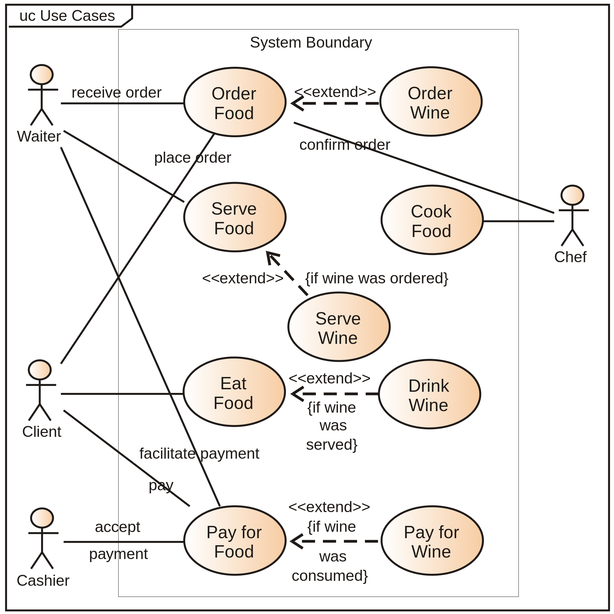
Use case diagram
A use case diagram is a graphical depiction of a user's possible interactions with a system. A use case diagram shows various use cases and different types of users the system has and will often be accompanied by other types of diagrams as well. The use cases are represented by either circles or ellipses. The actors are often shown as stick figures.
While a use case itself might drill into a lot of detail about every possibility, a use-case diagram can help provide a higher-level view of the system. It has been said before that "Use case diagrams are the blueprints for your system".
Due to their simplistic nature, use case diagrams can be a good communication tool for stakeholders. The drawings attempt to mimic the real world and provide a view for the stakeholder to understand how the system is going to be designed. Siau and Lee conducted research to determine if there was a valid situation for use case diagrams at all or if they were unnecessary. What was found was that the use case diagrams conveyed the intent of the system in a more simplified manner to stakeholders and that they were "interpreted more completely than class diagrams".
Hub AI
Use case diagram AI simulator
(@Use case diagram_simulator)
Use case diagram
A use case diagram is a graphical depiction of a user's possible interactions with a system. A use case diagram shows various use cases and different types of users the system has and will often be accompanied by other types of diagrams as well. The use cases are represented by either circles or ellipses. The actors are often shown as stick figures.
While a use case itself might drill into a lot of detail about every possibility, a use-case diagram can help provide a higher-level view of the system. It has been said before that "Use case diagrams are the blueprints for your system".
Due to their simplistic nature, use case diagrams can be a good communication tool for stakeholders. The drawings attempt to mimic the real world and provide a view for the stakeholder to understand how the system is going to be designed. Siau and Lee conducted research to determine if there was a valid situation for use case diagrams at all or if they were unnecessary. What was found was that the use case diagrams conveyed the intent of the system in a more simplified manner to stakeholders and that they were "interpreted more completely than class diagrams".
Recent media