Community hub
Recent from talks
Contribute something
Nothing was collected or created yet.
Unified Modeling Language
View on Wikipedia
| UML | |
|---|---|
| Family | Modeling language |
| Website | www |
The Unified Modeling Language (UML) is a general-purpose, object-oriented, visual modeling language that provides a way to visualize the architecture and design of a system, like a blueprint.[1][2] UML defines notation for many types of diagrams which focus on aspects such as behavior, interaction, and structure.
UML is both a formal metamodel and a collection of graphical templates. The metamodel defines the elements in an object-oriented model such as classes and properties. It is essentially the same thing as the metamodel in object-oriented programming (OOP), however for OOP, the metamodel is primarily used at run time to dynamically inspect and modify an application object model. The UML metamodel provides a mathematical, formal foundation for the graphic views used in the modeling language to describe an emerging system.
UML was created in an attempt by some of the major thought leaders in the object-oriented community to define a standard language at the OOPSLA '95 Conference. Originally, Grady Booch and James Rumbaugh merged their models into a unified model. This was followed by Booch's company Rational Software purchasing Ivar Jacobson's Objectory company and merging their model into the UML. At the time Rational and Objectory were two of the dominant players in the small world of independent vendors of object-oriented tools and methods.[3] The Object Management Group (OMG) then took ownership of UML.
The creation of UML was motivated by the desire to standardize the disparate nature of notational systems and approaches to software design at the time.[4] In 1997, UML was adopted as a standard by the Object Management Group (OMG) and has been managed by this organization ever since. In 2005, UML was also published by the International Organization for Standardization (ISO) and the International Electrotechnical Commission (IEC) as the ISO/IEC 19501 standard.[5] Since then the standard has been periodically revised to cover the latest revision of UML.[6]
Most developers do not use UML per se, but instead produce more informal diagrams, often hand-drawn. These diagrams, however, often include elements from UML.[7]: 536
Use
[edit]UML is primarily used for software development (in any industry or domain)[8] but also used outside elsewhere including business processes, system functions, database schemas, workflow in the legal systems, medical electronics, Health care systems, and hardware design.[9]
UML is designed for use with many object-oriented software development methods; both today and for the methods when it was first developed including OMT, Booch method, Objectory, and especially for RUP which it was originally intended to be used with when work began at Rational Software.[10] Although originally intended for object-oriented design documentation, UML has been used effectively in other contexts such as modeling business process.[11][12]
As UML is not inherently linked to a particular programming language, it can be used for modeling a system independent of language. Some UML tools generate source code from a UML model.[13]
Elements
[edit]
UML diagrams support visualizing system aspects like:[14]
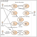
- Use case diagram for specifying user interactions with systems
- Class diagram for specifying structures, including data structures
- Activity diagram for specifying business process workflows
- Component diagram for specifying how components interface with other components
- Deployment diagram for specifying how components are deployed and executed on computational nodes
In addition to syntactical (notational) elements with well-defined semantics, UML diagrams also allow for free-form comments (notes) that explain aspects such as usage, constraints, and intents.
Sharing
[edit]UML models can be exchanged among UML tools via the XML Metadata Interchange (XMI) format.
Cardinality notation
[edit]As with database Chen, Bachman, and ISO ER diagrams, class models are specified to use "look-across" cardinalities, even though several authors (Merise,[15] Elmasri & Navathe,[16] amongst others[17]) prefer same-side or "look-here" for roles and both minimum and maximum cardinalities. Recent researchers (Feinerer[18] and Dullea et al.[19]) have shown that the "look-across" technique used by UML and ER diagrams is less effective and less coherent when applied to n-ary relationships of order strictly greater than 2.
Feinerer says: "Problems arise if we operate under the look-across semantics as used for UML associations. Hartmann[20] investigates this situation and shows how and why different transformations fail.", and: "As we will see on the next few pages, the look-across interpretation introduces several difficulties which prevent the extension of simple mechanisms from binary to n-ary associations."
Artifacts
[edit]
An artifact is the "specification of a physical piece of information that is used or produced by a software development process, or by deployment and operation of a system"[21] including models, source code, scripts, executables, tables in database systems, development deliverables, a design documents, and email messages.[21]
An artifact is the physical entity that is deployed to a node[21]. Other UML elements such as classes and components are first manifest into artifacts and instances of these artifacts are then deployed. Artifacts can be composed of other artifacts.
Metamodeling
[edit]
The OMG developed a metamodeling architecture to define UML, called the Meta-Object Facility (MOF).[22] MOF is designed as a four-layered architecture, as shown in the image at right. It provides a meta-meta model at the top, called the M3 layer. This M3-model is the language used by Meta-Object Facility to build metamodels, called M2-models.
The most prominent example of a Layer 2 Meta-Object Facility model is the UML metamodel, which describes UML itself. These M2-models describe elements of the M1-layer, and thus M1-models. These would be, for example, models written in UML. The last layer is the M0-layer or data layer. It is used to describe runtime instances of the system.[23]
The metamodel can be extended using a mechanism called stereotyping. This has been criticized as being insufficient/untenable by Brian Henderson-Sellers and Cesar Gonzalez-Perez in "Uses and Abuses of the Stereotype Mechanism in UML 1.x and 2.0".[24]
Diagrams
[edit]| UML diagram types |
|---|
| Structural UML diagrams |
| Behavioral UML diagrams |
UML 2 defines many types of diagrams – shown as a taxonomy in the image.[14][25]

Structure diagrams
[edit]Structure diagrams emphasize the structure of the system – using objects, classifiers, relationships, attributes and operations. They are used to document software architecture.
- Class diagram – Describes the structure of a class
- Component diagram – Describes how a software system is split into components and dependencies between the components
- Composite structure diagram
- Deployment diagram
- Object diagram
- Package diagram
- Profile diagram
Behavior diagrams
[edit]Behavior diagrams emphasize the behavior of a system by showing collaborations among objects and changes to the internal states of objects. They are used to describe the functionality of a system.
- Activity diagram – Describes the business and operational activities of components
- State machine diagram
- Use case diagram – Depicts of a user's interaction with a system[26]
Interaction diagrams
[edit]Interaction diagrams, a subset of behavior diagrams, emphasize the flow of control and data between components of a system.
- Communication diagram – shows communication between components
- Interaction overview diagram
- Sequence diagram – shows interactions arranged in time sequence; can be drawn via tools such as Lucidchart and Draw.io
- Timing diagram – focuses on timing constraints
Examples
[edit]-
 Component diagram
 -
 Class diagram
 -
 Activity diagram
 -
 Use case diagram
 -
 Use case diagram
 -
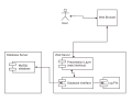 Deployment diagram


Adoption
[edit]In 2013, UML had been marketed by OMG for many contexts, but aimed primarily at software development with limited success.[12][27]
It has been treated, at times, as a design silver bullet, which leads to problems. UML misuse includes overuse (designing every part of the system with it, which is unnecessary) and assuming that novices can design with it.[28]
It is considered a large language, with many constructs. Some people (including Jacobson) feel that UML's size hinders learning and therefore uptake.[29]
Visual Studio dropped support for UML in 2016 due to lack of use.[30]
According to Google Trends, use of the term UML has declined since 2004 although leveled off in the last 5 years.[31]
History
[edit]
UML has evolved since the second half of the 1990s and has its roots in the object-oriented programming methods developed in the late 1980s and early 1990s. The image shows a timeline of the history of UML and other object-oriented modeling methods and notation.
Origin
[edit]Rational Software hired James Rumbaugh from General Electric in 1994 and after that, the company became the source for two of the most popular object-oriented modeling approaches of the day:[32] Rumbaugh's object-modeling technique (OMT) and Grady Booch's method. They were soon assisted in their efforts by Ivar Jacobson, the creator of the object-oriented software engineering (OOSE) method, who joined them at Rational in 1995.[4]
UML 1.x
[edit]UML is originally based on the notations of the Booch method, the object-modeling technique (OMT), and object-oriented software engineering (OOSE), which were integrated into a single language.[14] UML was developed at Rational Software in 1994–1995, with further development led by them through 1996.[4]
Under the technical leadership of Rumbaugh, Jacobson, and Booch, a consortium called the UML Partners was organized in 1996 to complete the Unified Modeling Language (UML) specification and propose it to the Object Management Group (OMG) for standardization. The partnership also contained additional interested parties (for example HP, DEC, IBM, and Microsoft). The UML Partners' UML 1.0 draft was proposed to the OMG in January 1997 by the consortium. During the same month, the UML Partners formed a group, designed to define the exact meaning of language constructs, chaired by Cris Kobryn and administered by Ed Eykholt, to finalize the specification and integrate it with other standardization efforts. The result of this work, UML 1.1, was submitted to the OMG in August 1997 and adopted by the OMG in November 1997.[4][33]
After the first release, a task force was formed[4] to improve the language, which released several minor revisions, 1.3, 1.4, and 1.5.[34]
The standards it produced (as well as the original standard) have been noted as being ambiguous and inconsistent.[35]
UML 2
[edit]UML 2.0 major revision replaced version 1.5 in 2005, which was developed with an enlarged consortium to improve the language further to reflect new experiences on the usage of its features.[36]
Although UML 2.1 was never released as a formal specification, versions 2.1.1 and 2.1.2 appeared in 2007, followed by UML 2.2 in February 2009. UML 2.3 was formally released in May 2010.[37] UML 2.4.1 was formally released in August 2011.[37] UML 2.5 was released in October 2012 as an "In progress" version and was officially released in June 2015.[37] The formal version 2.5.1 was adopted in December 2017.[1]
There are four parts to the UML 2.x specification:
- The Superstructure that defines the notation and semantics for diagrams and their model elements
- The Infrastructure that defines the core metamodel on which the Superstructure is based
- The Object Constraint Language (OCL) for defining rules for model elements
- The UML Diagram Interchange that defines how UML 2 diagram layouts are exchanged
Until UML 2.4.1, the latest versions of these standards were:[38]
- UML Superstructure version 2.4.1
- UML Infrastructure version 2.4.1
- OCL version 2.3.1
- UML Diagram Interchange version 1.0.
Since version 2.5, the UML Specification has been simplified (without Superstructure and Infrastructure), and the latest versions of these standards are now:[39]
- UML Specification 2.5.1
- OCL version 2.4
It continues to be updated and improved by the revision task force, who resolve any issues with the language.[40]
See also
[edit]- Business Process Model and Notation – Graphical representation for specifying business processes
- C4 model – Technique for modelling software architecture
- Department of Defense Architecture Framework – Enterprise architecture framework
- DOT (graph description language) – File format
- List of Unified Modeling Language tools
- Real-Time UML – the application of the Unified Modelling Language (UML)
- MODAF – Enterprise architecture framework
- Model-based testing – Application of model-based design
- Model-driven engineering – Software development methodology
- Modeling and Analysis of Real Time and Embedded systems
- Object-oriented role analysis and modeling
- Process Specification Language – Set of logic terms used to describe processes
- Systems Modeling Language – General-purpose modeling language
References
[edit]- ^ a b Unified Modeling Language 2.5.1. Object Management Group Document Number formal/2017-12-05. Object Management Group Standards Development Organization. December 2017.
- ^ [1412.2458] Systems, Views and Models of UML. By Ruth Breu Radu Grosu Franz Huber Bernhard Rumpe Wolfgang Schwerin. arXiv arxiv.org
- ^ "From Unified Method to Unified Language". modelseverywhere.wordpress.com. 13 November 2010. Retrieved 19 December 2013.
- ^ a b c d e Unified Modeling Language User Guide, The (2 ed.). Addison-Wesley. 2005. p. 496. ISBN 0321267974. See the sample content: look for history
- ^ "ISO/IEC 19501:2005 - Information technology - Open Distributed Processing - Unified Modeling Language (UML) Version 1.4.3". Iso.org. 1 April 2005. Retrieved 7 May 2015.
- ^ "ISO/IEC 19505-1:2012 - Information technology - Object Management Group Unified Modeling Language (OMG UML) - Part 1: Infrastructure". Iso.org. 20 April 2012. Retrieved 10 April 2014.
- ^ Sebastian Baltes; Stephan Diehl (11 November 2014). "Sketches and diagrams in practice". Proceedings of the 22nd ACM SIGSOFT International Symposium on Foundations of Software Engineering. FSE 2014. Association for Computing Machinery. pp. 530–541. arXiv:1706.09172. doi:10.1145/2635868.2635891. ISBN 978-1-4503-3056-5. S2CID 2436333.
- ^ Conallen, Jim (1999). "Modeling Web Application Architectures with UML" (PDF). Communications of the ACM. 42 (10): 63–70. doi:10.1145/317665.317677.
- ^ "Grady Booch, Jacobson and Rumbaugh book".
{{cite web}}: Missing or empty|url=(help) - ^ John Hunt (2000). The Unified Process for Practitioners: Object-oriented Design, UML and Java. Springer, 2000. ISBN 1-85233-275-1. p. 5.door
- ^ Satish Mishra (1997). "Visual Modeling & Unified Modeling Language (UML): Introduction to UML" Archived 20 July 2011 at the Wayback Machine. Rational Software Corporation. Accessed 9 November 2008.
- ^ a b "UML, Success Stories". Retrieved 9 April 2014.
- ^ "Importance of UML".
- ^ a b c "OMG Unified Modeling Language (OMG UML), Superstructure. Version 2.4.1". Object Management Group. Retrieved 9 April 2014.
- ^ Hubert Tardieu, Arnold Rochfeld and René Colletti La methode MERISE: Principes et outils (Paperback - 1983)
- ^ Elmasri, Ramez, B. Shamkant, Navathe, Fundamentals of Database Systems, third ed., Addison-Wesley, Menlo Park, CA, USA, 2000.
- ^ Paolo Atzeni; Wesley Chu; Hongjun Lu; Shuigeng Zhou; Tok Wang Ling, eds. (27 October 2004). Conceptual Modeling – ER 2004: 23rd International Conference on Conceptual Modeling, Shanghai, China, November 8–12, 2004. Lecture Notes in Computer Science 3288 (2004 ed.). Springer. ISBN 3540237232.
- ^ Ingo Feinerer (March 2007). A Formal Treatment of UML Class Diagrams as an Efficient Method for Configuration Management (PDF) (Doctor of Technical Sciences thesis). Vienna: Technical University of Vienna. Archived from the original (PDF) on 29 June 2024. Retrieved 25 May 2024.
- ^ James Dullea; Il-Yeol Song; Ioanna Lamprou (1 November 2003). "An analysis of structural validity in entity-relationship modeling". Data & Knowledge Engineering. 47 (2): 167–205. doi:10.1016/S0169-023X(03)00049-1.
- ^ Sven Hartmann (17 January 2003). Reasoning about participation constraints and Chen's constraints. ADC '03: Proceedings of the 14th Australasian database conference. Australian Computer Society. pp. 105–113.

- ^ a b c "Artifacts". Unified Modeling Language 2.5.1. OMG Document Number formal/2017-12-05. Object Management Group Standards Development Organization (OMG SDO). December 2017. p. 656.
- ^ Iman Poernomo (2006) "The Meta-Object Facility Typed Archived 30 June 2016 at the Wayback Machine" in: Proceeding SAC '06 Proceedings of the 2006 ACM symposium on Applied computing. pp. 1845–1849
- ^ "UML 2.4.1 Infrastructure". Omg.org. 5 August 2011. Retrieved 10 April 2014.
- ^ Brian Henderson-Sellers; Cesar Gonzalez-Perez (1 October 2006). "Uses and abuses of the stereotype mechanism in UML 1.x and 2.0". MoDELS '06: Proceedings of the 9th International Conference on Model Driven Engineering Languages and Systems. Lecture Notes in Computer Science 4199. 4199. Berlin, Germany: Springer-Verlag: 16–26. doi:10.1007/11880240_2. ISBN 978-3-540-45772-5.
- ^ Jon Holt Institution of Electrical Engineers (2004). UML for Systems Engineering: Watching the Wheels IET, 2004, ISBN 0-86341-354-4. p. 58
- ^ Manuel Almendros-Jiménez, Jesús & Iribarne, Luis. (2007). Describing Use-Case Relationships with Sequence Diagrams. Comput. J.. 50. 116-128. 10.1093/comjnl/bxl053.
- ^ "UML 2.5: Do you even care?". Dr. Dobb's. "UML truly is ubiquitous"
- ^ "Death by UML Fever".
- ^ "Ivar Jacobson on UML, MDA, and the future of methodologies".
- ^ Krill, Paul (18 October 2016). "UML to be ejected from Microsoft Visual Studio". InfoWorld. Retrieved 23 July 2023.
- ^ "Google Trends". Google Trends. Archived from the original on 23 July 2023. Retrieved 23 July 2023.
- ^ Andreas Zendler (1997) Advanced Concepts, Life Cycle Models and Tools for Objeckt-Oriented Software Development. p. 122
- ^ "UML Specification version 1.1 (OMG document ad/97-08-11)". Omg.org. Retrieved 22 September 2011.
- ^ "UML". Omg.org. Retrieved 10 April 2014.
- ^ Génova et alia 2004 "Open Issues in Industrial Use Case Modeling"
- ^ "UML 2.0". Omg.org. Retrieved 22 September 2011.
- ^ a b c "UML". Omg.org. Retrieved 22 September 2011.
- ^ OMG. "OMG Formal Specifications (Modeling and Metadata paragraph)". Retrieved 12 February 2016.
- ^ OMG. "about the unified modeling language specification". Retrieved 22 February 2020.
- ^ "Issues for UML 2.6 Revision task Force mailing list". Omg.org. Retrieved 10 April 2014.
Further reading
[edit]- Tegarden, David et al. (2025). Systems Analysis and Design: An Object-Oriented Approach with UML (7th ed.). Wiley. ISBN 978-1-394-33172-7.
- Ambler, Scott William (2004). The Object Primer: Agile Model Driven Development with UML 2. Cambridge University Press. ISBN 0-521-54018-6. Archived from the original on 31 January 2010. Retrieved 29 April 2006.
- Chonoles, Michael Jesse; James A. Schardt (2003). UML 2 for Dummies. Wiley Publishing. ISBN 0-7645-2614-6.
- Fowler, Martin (2004). UML Distilled: A Brief Guide to the Standard Object Modeling Language (3rd ed.). Addison-Wesley. ISBN 0-321-19368-7.
- Jacobson, Ivar; Grady Booch; James Rumbaugh (1998). The Unified Software Development Process. Addison Wesley Longman. ISBN 0-201-57169-2.
- Martin, Robert Cecil (2003). UML for Java Programmers. Prentice Hall. ISBN 0-13-142848-9.
- Noran, Ovidiu S. "Business Modelling: UML vs. IDEF" (PDF). Archived from the original (PDF) on 18 July 2024. Retrieved 14 November 2022.
- Horst Kargl. "Interactive UML Metamodel with additional Examples".
- Penker, Magnus; Hans-Erik Eriksson (2000). Business Modeling with UML. John Wiley & Sons. ISBN 0-471-29551-5.
- Douglass, Bruce Powel. "Bruce Douglass: Real-Time Agile Systems and Software Development" (web). Retrieved 1 January 2019.
- Douglass, Bruce (2014). Real-Time UML Workshop 2nd Edition. Newnes. ISBN 978-0-471-29551-8.
- Douglass, Bruce (2004). Real-Time UML 3rd Edition. Newnes. ISBN 978-0321160768.
- Douglass, Bruce (2002). Real-Time Design Patterns. Addison-Wesley Professional. ISBN 978-0201699562.
- Douglass, Bruce (2009). Real-Time Agility. Addison-Wesley Professional. ISBN 978-0321545497.
- Douglass, Bruce (2010). Design Patterns for Embedded Systems in C. Newnes. ISBN 978-1856177078.
External links
[edit]- Official website

- Current UML specification: Unified Modeling Language 2.5.1. OMG Document Number formal/2017-12-05. Object Management Group Standards Development Organization (OMG SDO). December 2017.
| Actors |
|  | |||||||||||
|---|---|---|---|---|---|---|---|---|---|---|---|---|---|
| Concepts |
| ||||||||||||
| Diagrams |
| ||||||||||||
| Derived languages | |||||||||||||
| Other topics | |||||||||||||
International Organization for Standardization (ISO) standards | |
|---|---|
| 1–9999 |
|
| 10000–19999 |
|
| 20000–29999 |
|
| 30000+ | |
| International | |
|---|---|
| National | |
| Other | |
Unified Modeling Language
View on GrokipediaOverview
Definition
The Unified Modeling Language (UML) is a general-purpose, developmental, modeling language for specifying, visualizing, constructing, and documenting the artifacts of software systems.[6] It provides a standardized graphical notation that enables developers and architects to represent system structures, behaviors, and interactions in a consistent manner, facilitating communication among stakeholders throughout the software development lifecycle.[6] UML has been standardized by the Object Management Group (OMG), an international, non-profit consortium, since its initial adoption as version 1.1 in November 1997.[7] As a non-proprietary specification, UML is openly available for use and extension by the software industry, ensuring broad accessibility without licensing restrictions tied to specific vendors.[6] This standardization promotes interoperability among modeling tools and methodologies, allowing organizations to adopt UML without proprietary lock-in.[6] At its core, UML functions as a visual notation system that integrates multiple complementary views of a system, such as structural, behavioral, and functional perspectives, to support object-oriented analysis and design processes.[6] These views are expressed through diagrams that abstract complex software architectures into comprehensible representations, aiding in the identification of requirements, design flaws, and implementation strategies.[6] Unlike programming languages, which are imperative and produce executable code, UML is declarative and diagrammatic, focusing on high-level modeling rather than low-level implementation details.[6]Purpose and Benefits
The Unified Modeling Language (UML) primarily aims to specify, visualize, construct, and document the artifacts of software systems, enabling software engineers to model system structure and behavior in a standardized manner.[8] This facilitates effective communication among stakeholders, including developers, analysts, and non-technical users, by providing a common visual language that bridges gaps in technical understanding and requirements articulation.[9] By abstracting complex designs into diagrams, UML reduces the inherent complexity of large-scale systems, allowing teams to focus on high-level architecture rather than implementation details from the outset.[10] Key benefits of UML include enhanced system understanding through its graphical notations, which clarify relationships and components, and early error detection during design validation against requirements, thereby lowering the risk of failures in production.[2] Its methodology-independent nature aligns well with both iterative approaches, such as agile development, where models evolve incrementally, and traditional waterfall processes that emphasize upfront planning.[9] Unlike informal sketches, which often lead to ambiguity and misinterpretation, UML's standardized, precise notation minimizes such issues, promoting unambiguous designs that support code generation and maintenance.[10] UML's extensibility further amplifies its benefits, as users can adapt the language through profiles to suit domain-specific needs, such as real-time embedded systems via the MARTE profile or business process modeling extensions.[9] This customization enables precise modeling for specialized applications without altering the core language, fostering reusability and interoperability across tools and platforms.[10] Overall, these features contribute to scalable, robust software development by encapsulating intellectual property in a technology-neutral form.[8]History
Origins
In the early 1990s, the object-oriented software engineering field experienced significant fragmentation, with numerous competing modeling methods emerging to support the growing adoption of object-oriented paradigms. Key among these were Grady Booch's iterative method for object-oriented design, introduced in the late 1980s and focused on implementation-level modeling; James Rumbaugh's Object Modeling Technique (OMT), developed in 1991 at General Electric and emphasizing analysis for data-intensive systems through object, dynamic, and functional models; and Ivar Jacobson's Object-Oriented Software Engineering (OOSE), published in 1992, which introduced use cases to capture system behavior and requirements.[11][11] This proliferation of notations created challenges for practitioners, as no single approach dominated, leading to inconsistencies in communication and tool support across projects. To consolidate these best practices, Rational Software—where Booch was already employed—began unification efforts in 1994 when Rumbaugh joined the company from General Electric, merging OMT and the Booch method into an initial "Unified Method."[12][11] In 1995, Jacobson also joined Rational, integrating OOSE's use case concepts, and the trio—Booch, Rumbaugh, and Jacobson—became known as the "Three Amigos" for their collaborative leadership in standardizing object-oriented modeling.[13][11] The drive for unification stemmed from industry demands for a common visual language to reduce confusion and enhance interoperability in software design, particularly as object-oriented methods gained traction for complex systems development. These efforts were influenced by prior Object Management Group (OMG) standards, such as the Common Object Request Broker Architecture (CORBA), which had established a framework for distributed object computing since 1991 and underscored the need for standardized modeling to support platform-independent architectures.[13]Development of UML 1.x
The development of UML 1.x marked the formal standardization of a unified notation for object-oriented modeling, building briefly on the integration of methods from Grady Booch, James Rumbaugh, and Ivar Jacobson at Rational Software. In January 1997, Rational Software and its partners submitted UML version 1.0 to the Object Management Group (OMG) in response to a request for proposals aimed at standardizing software design practices. This initial submission was refined through collaborative review, leading to version 1.1, which was submitted in September 1997 and adopted by the OMG in late 1997 as UML 1.1.[14][15] UML 1.1 established the core structure of the language, introducing nine diagram types to support both static and dynamic modeling aspects, including use case diagrams for capturing system requirements, class diagrams for defining structural relationships, and sequence diagrams for illustrating object interactions over time. Led by Rational Software, the development involved contributions from a consortium of about 20 companies, such as Microsoft, Hewlett-Packard, Oracle, IBM, and Unisys, which helped harmonize diverse modeling semantics from earlier fragmented approaches.[15][3][14][16] Subsequent minor revisions refined UML 1.x without major overhauls. UML 1.3, adopted in February 2000, enhanced use case modeling with relationships like «include» and «extend», tightened activity diagram semantics to better support concurrency via fork/join constructs, and improved overall precision in the metamodel. UML 1.5, adopted in March 2003, introduced formal action semantics to provide executable foundations for behavioral models, enabling better integration with implementation tools while maintaining backward compatibility with prior 1.x versions. These updates were managed through OMG's Revision Task Force, ensuring iterative improvements based on industry feedback.[17][18]Evolution to UML 2.x
The Unified Modeling Language (UML) 2.0 was formally adopted by the Object Management Group (OMG) in July 2005 as a major revision to address key limitations in the UML 1.x series.[19] These shortcomings included imprecise semantics, particularly for actions, which hindered executable models; excessive complexity that overwhelmed users; inadequate support for component-based development; and challenges in diagram scalability and interchangeability across tools.[20] The revision aimed to enhance usability while expanding applicability to modern software paradigms like concurrent and distributed systems.[21] Key enhancements in UML 2.0 included an expansion from nine diagram types in UML 1.x to thirteen, incorporating new ones such as communication, composite structure, interaction overview, and timing diagrams to better represent interactions and structures.[22] It provided stronger support for component-based architectures by elevating components to a first-class modeling element throughout the lifecycle and improved concurrency modeling through refined behavioral semantics for threads and processes.[20] Additionally, formal metamodel refinements separated the language into infrastructure (core abstractions) and superstructure (user-facing elements), enabling more precise definitions and easier customization via profiles.[23] Subsequent iterative releases refined these foundations. UML 2.1, released in 2007, focused on diagram improvements, such as enhanced notations for sequence and activity diagrams to clarify interactions and flows.[24] UML 2.4, adopted in 2011 following interim updates, introduced better partitioning mechanisms in activity diagrams for organizing complex behaviors into swimlanes and regions, aiding scalability in large models. UML 2.5, finalized in June 2015, emphasized simplification by rewriting the specification to reduce redundancy and flatten hierarchies while preserving semantics, responding to an OMG request for consolidation.[25] UML 2.x also introduced lightweight diagram extensions, such as optional frames and fragments, to allow concise notations without full formality, alongside more precise execution semantics based on token-flow models for activities, bridging the gap between modeling and code generation.[22]Recent Developments
The UML 2.5.1 specification, released by the Object Management Group (OMG) in December 2017, served as a maintenance update to UML 2.5, incorporating minor clarifications and bug fixes without introducing substantive changes to the language's structure or semantics.[26][27] This revision addressed issues identified in prior versions, such as inconsistencies in metamodel definitions, to enhance clarity for tool implementers and users.[28] As of 2025, no major new version of UML beyond 2.5.1 has been adopted, reflecting a period of stability focused on refinement rather than overhaul.[29] Ongoing OMG efforts have emphasized profiles and subsets to extend UML's applicability in specialized domains. The Foundational UML Subset (fUML), an executable subset of UML, continues to evolve, with version 1.5 providing precise operational semantics for structural and behavioral models, enabling direct execution of UML activities without additional code generation. Recent advancements include compiler-like optimizations for fUML to reduce execution overhead in model-driven engineering, as demonstrated in implementations supporting precise behavioral specifications.[30] Similarly, the Systems Modeling Language (SysML), a UML profile for systems engineering, saw significant updates with SysML v1.7 adopted in June 2024 for minor enhancements and SysML v2.0 finalized in July 2025, introducing improved textual notation, API support, and interoperability for complex system architectures.[31][32] These developments build on UML's foundational elements to address modern engineering challenges like model execution and systems integration.[33] UML has seen increased alignment with complementary standards for business and process modeling. Integration with Business Process Model and Notation (BPMN) facilitates hybrid approaches, where UML structural diagrams complement BPMN's process flows, as outlined in frameworks mapping BPMN elements to executable UML for end-to-end modeling.[34] Emerging AI-driven tools further support UML adoption by automating diagram generation from natural language or code, with platforms like Visual Paradigm AI producing editable class and sequence diagrams from use case descriptions to streamline design workflows.[35] Community-driven initiatives underscore UML's adaptability in contemporary software practices. Open-source contributions, such as the fUML Reference Implementation on GitHub, provide accessible virtual machines for executing UML models, fostering experimentation and tool development.[36] Discussions within the modeling community highlight UML's relevance in DevOps and microservices architectures, where component and deployment diagrams visualize service dependencies and orchestration, aiding agile teams in managing distributed systems.[37][38]Core Concepts
Basic Elements
The Unified Modeling Language (UML) employs a set of fundamental graphical symbols and notations to represent key modeling concepts, forming the building blocks for all UML diagrams. These elements include classifiers such as classes and use cases, instances like objects, and connectors like associations, which together enable the visualization of system structures and behaviors.[5] Core symbols in UML include classes, depicted as rectangles divided into compartments for the class name (in bold), attributes, and operations; objects, shown as rectangles with underlined names specifying the object instance and its class (e.g.,myObject: ClassName); actors, represented as stick figures or rectangles stereotyped as «actor» to denote external entities interacting with the system; and use cases, illustrated as ovals containing the use case name. Attributes are listed in the second compartment of a class with syntax like name: Type [multiplicity], while operations appear in the third compartment as visibility operationName(parameter: Type): ReturnType. Associations are solid lines connecting elements, often annotated with role names, multiplicities (e.g., 0..* for zero or more), and direction arrows to indicate navigability.[5]
UML defines several relationship types to express connections between elements. Generalization, representing inheritance, is a solid line ending in a hollow triangle pointing to the superclass. Realization indicates implementation, using a dashed line with a hollow triangle from the realizing element to the interface or specification. Dependency shows reliance, notated as a dashed line with an open arrow from the dependent (client) to the depended-upon (supplier) element. Aggregation and composition, both forms of whole-part relationships, use solid lines with a hollow diamond (aggregation, shared ownership) or filled diamond (composition, exclusive ownership) at the whole end.[5]
Visibility levels control access to attributes and operations, prefixed by standard symbols: + for public (accessible to all), - for private (accessible only within the class), # for protected (accessible within the class and subclasses), and ~ for package (accessible within the same package). These notations ensure precise modeling of encapsulation in object-oriented designs.[5]
Stereotypes and constraints provide mechanisms for extending and customizing UML elements without altering the core language. Stereotypes are denoted by guillemets enclosing a name (e.g., <<interface>> applied to a class to specify it defines a contract of operations without implementation), allowing domain-specific interpretations. Constraints, expressed in braces as {booleanExpression} or natural language, restrict element properties (e.g., {self.size > 0} on an attribute to enforce non-emptiness). These features enhance UML's expressiveness for specialized modeling needs.[5]
Notation and Semantics
The Unified Modeling Language (UML) employs a dual notation system comprising graphical and textual representations to specify models precisely and unambiguously. Graphical notation utilizes diagrams with standardized visual elements, such as rectangles for classes and solid lines for associations, to depict structural and behavioral aspects of systems. This visual syntax facilitates intuitive communication among stakeholders while adhering to formal rules for rendering, including adornments like multiplicity indicators and stereotypes enclosed in guillemets (e.g., «abstract»). Textual notation, primarily through the Object Constraint Language (OCL), complements graphics by expressing precise constraints, preconditions, and postconditions that cannot be fully captured visually, such as invariants on model elements. OCL is integrated into UML as a side-effect-free, declarative language for formal specifications, allowing constraints to be attached to diagram elements or defined separately.[5] UML semantics are stratified into three interconnected layers to ensure consistent interpretation and execution of models. The abstract syntax layer, defined by the UML metamodel, establishes the foundational vocabulary and structure of model elements, such as classifiers, properties, and relationships, using a Meta-Object Facility (MOF)-based framework to represent the language's core concepts without regard to visualization. The concrete syntax layer specifies the visual rules for rendering these abstract elements, including layout conventions, line styles, and compartment structures in diagrams, enabling human-readable notations while maintaining fidelity to the abstract model. The behavioral semantics layer addresses dynamic aspects, defining how model elements evolve over time, such as token flows in activities, state transitions, and message sequences in interactions, with operational rules for execution and validation. These layers collectively support model-driven engineering by bridging informal diagrams to formal, executable specifications.[5] Cardinality notation in UML specifies the allowable number of instances participating in associations, generalizations, and other relationships, using a multiplicity range expressed as [lower..upper] at association ends or connector roles. Common notations include 0..1 for optional participation (zero or one instance), 1..* for mandatory one-or-more instances, and * (equivalent to 0..) for unbounded multiplicity. For instance, an association between classes might denote one end as 1 (exactly one) and the other as 0.., indicating a one-to-many relationship. These multiplicities enforce constraints during model validation and code generation, ensuring structural integrity.[5] OCL provides a formal mechanism to articulate constraints beyond graphical notation, using a context declaration followed by invariant, pre-, or postconditions. A basic example iscontext Class inv: self.attribute > 0, which specifies that an attribute's value must always be positive for instances of the Class. More complex constraints might include context Reception inv: name = signal.name, ensuring a reception's name matches its associated signal, or context Signal inv: ownedAttribute->size() = ownedParameter->size(), verifying that a signal's attributes align in count with its parameters. These expressions leverage OCL's type-safe navigation and collection operations to define precise, machine-checkable rules integrated with UML diagrams.[5][39]