
Community hub
Recent from talks
Contribute something
Nothing was collected or created yet.
Package diagram
View on Wikipedia
| UML diagram types |
|---|
| Structural UML diagrams |
| Behavioral UML diagrams |
A package diagram[1] in the Unified Modeling Language depicts "specializations for Models and for Profiles that organize extensions to UML."[1]
Overview
[edit]In addition to the standard UML Dependency relationship, there are two special types of dependencies defined between packages:
- package import
- package merge
A package import is "a directed relationship between an importing namespace and a package, indicating that the importing namespace adds the names of the members of the package to its own namespace."[2] By default, an unlabeled dependency between two packages is interpreted as a package import relationship. In this relationship, elements within the target package will be imported into the source package.
A package merge is "a directed relationship between two packages, that indicates that the contents of the two packages are to be combined. It is very similar to Generalisation in the sense that the source element conceptually adds the characteristics of the target element to its own characteristics resulting in an element that combines the characteristics of both".[3] In this relationship, if an element exists within both the source package and the target package, then the source element's definition will be expanded to include the target element's definition.

In the current Unified Modeling Language 2.5.1 (December 2017), Package Merge is no longer used within the specification. "Every metaclass is specified completely in one clause."[4]
Elements
[edit]- Package: a general purpose mechanism for organising model elements & diagrams into groups. It provides an encapsulated namespace within which all the names must be unique. It is used to group semantically related elements. It is a namespace as well as an element that can be contained in other packages' namespaces.
- Class: a representation of an object that reflects its structure and behavior within the system. It is a template from which running instances are created. Classes usually describe the logical structure of the system.
- Interface: a specification of behavior. An implementation class must be written to support the behavior of an interface class.
- Object: an instance of a class. It is often used in analysis to represent an artifact or other item.
- Table: a stereotyped class.
Usage
[edit]Package diagrams can use packages containing use cases to illustrate the functionality of a software system.
Package diagrams can use packages that represent the different layers of a software system to illustrate the layered architecture of a software system. The dependencies between these packages can be adorned with labels / stereotypes to indicate the communication mechanism between the layers.
When to use
[edit]- It is used in large scale systems to picture dependencies between major elements in the system
- Package diagrams represent a compile time grouping mechanism.
References
[edit]- ^ a b "Packages". Unified Modeling Language 2.5.1. OMG Document Number formal/2017-12-05. Object Management Group Standards Development Organization (OMG SDO). December 2017. p. 241.
- ^ "Namespaces". Unified Modeling Language 2.5.1. OMG Document Number formal/2017-12-05. Object Management Group Standards Development Organization (OMG SDO). December 2017. p. 27.
- ^ OMG Unified Modeling Language (OMG UML), Infrastructure, V2.1.2 Archived 2017-01-09 at the Wayback Machine, p. 160.
- ^ "Specification Simplification". Unified Modeling Language 2.5.1. OMG Document Number formal/2017-12-05. Object Management Group Standards Development Organization (OMG SDO). December 2017. p. 11.
This article needs additional citations for verification. (February 2009) |
External links
[edit]| Actors |
|  | |||||||||||
|---|---|---|---|---|---|---|---|---|---|---|---|---|---|
| Concepts |
| ||||||||||||
| Diagrams |
| ||||||||||||
| Derived languages | |||||||||||||
| Other topics | |||||||||||||
Package diagram
View on GrokipediaIntroduction
Definition and Purpose
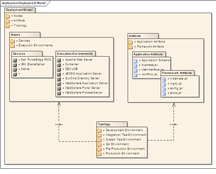
A package diagram is a type of static structure diagram in the Unified Modeling Language (UML) that illustrates the hierarchical organization of packages, their contents, and dependencies between them.[1] Packages serve as namespaces that group related model elements, such as classes, interfaces, and other artifacts, into logical units, enabling a structured representation of the system's components.[1] This diagram type focuses on the packaging mechanism without delving into the internal details of individual elements, providing an overview of how the system is divided into modular parts.[2] The primary purpose of a package diagram is to offer a high-level view of system architecture by organizing elements into packages, which facilitates modularity, namespace management, and comprehension of inter-package relationships.[1] It supports the encapsulation of related functionality, allowing developers to manage complexity in large-scale projects by defining clear boundaries and interactions between subsystems or modules.[2] Through notations like dependencies and imports, the diagram reveals how packages rely on one another, aiding in the design of reusable and maintainable software structures.[1] Key benefits of package diagrams include simplifying the visualization of large systems by grouping elements hierarchically, which reduces cognitive load and enhances navigability of complex models.[2] They promote reuse through encapsulation, as packages can be developed, tested, and deployed independently while exposing only necessary interfaces.[1] Additionally, by highlighting dependencies, these diagrams assist in identifying potential impacts during system maintenance and evolution, supporting better decision-making for refactoring or extension.[2]Role in UML
Package diagrams serve as a structural backbone within the Unified Modeling Language (UML), enabling the organization of model elements from various other diagrams into logical, semantically related units. By grouping elements such as classes from class diagrams or use cases from use case diagrams into packages, they provide a high-level view of the system's architecture, minimizing dependencies and promoting modularity. This integration facilitates the management of complex models by establishing namespaces that ensure unique identification of elements within their scopes, as defined in the UML specification.[3] In the broader UML ecosystem, package diagrams complement behavioral diagrams, such as sequence or activity diagrams, by illustrating static dependencies that underpin dynamic interactions and flows. For instance, dependencies between packages can reveal how structural relationships influence runtime behaviors, offering context for analyzing system dynamics without delving into implementation details. Additionally, they support deployment diagrams by mapping logical packages to physical components or nodes, aiding in the translation of abstract models to deployable artifacts in multi-layered applications.[3] As prerequisites for other UML models, package diagrams are essential for defining namespaces and organizational boundaries before elaborating on internal contents in diagrams like class or use case diagrams. This foundational role ensures that subsequent modeling activities build upon a coherent structure, supporting model reuse, extension through profiles, and interoperability in collaborative environments.[3]Historical Development
Origins in UML 1.0
The package diagram was introduced in the Unified Modeling Language (UML) 1.0 specification, which was formally adopted by the Object Management Group (OMG) in November 1997 following an initial submission in January 1997.[4][5] This diagram type emerged as part of UML's effort to standardize object-oriented modeling practices, providing a structural view for organizing system elements at a high level of abstraction. The design rationale for package diagrams stemmed from the need to unify and simplify grouping mechanisms present in predecessor methodologies, such as the Object Modeling Technique (OMT) and the Booch method. OMT employed subsystems for modular organization but lacked flexible namespace handling, while the Booch method used categories for clustering related classes without robust support for hierarchical decomposition or inter-group dependencies. These limitations hindered effective modeling of large-scale software systems, prompting the UML creators—Grady Booch, James Rumbaugh, and Ivar Jacobson—to consolidate such constructs into a single, versatile "package" element. As noted in early UML documentation, "we decided to collapse these two mechanisms into one all-purpose packaging construct," allowing stereotypes to differentiate uses like logical or physical groupings while avoiding redundant features.[6] In UML 1.0, package diagrams emphasized basic containment and dependency relationships to facilitate software partitioning. Packages served as containers that owned their contents, establishing nested namespaces where elements like classes or other packages could be uniquely identified (e.g., via qualified names such as PackageName::ElementName). Dependencies, depicted as dashed arrows, represented import/export relationships between packages, enabling visibility control and modular reuse without exposing internal details. This focus supported the partitioning of complex models into manageable units, addressing the scalability issues in pre-UML approaches.[6]Changes in Later UML Versions
In UML 1.1, released in 1997, package diagrams received minor clarifications primarily focused on visibility mechanisms, such as combining the visibility of elements within a package with the package's own visibility level, without introducing major structural additions or new relationships.[7] The significant advancements occurred with UML 2.0 in 2005, which introduced package merge as a mechanism to extend one package's contents with another's, allowing for reusable model extensions particularly useful in template bindings and profile definitions. This version also enhanced dependency relationships through specific stereotypes, including<<import>> for public visibility (enabling unqualified name use across package boundaries) and <<access>> for private visibility (restricting access to the importing package only), replacing more general usage dependencies from prior versions. Additionally, UML 2.0 improved support for profiles by integrating packageable elements more seamlessly into metamodel extensions, facilitating domain-specific language development.[8]
UML 2.5, finalized in 2015, brought refinements to nested package notation and semantics, notably altering package merge behavior for nested structures: sub-packages are now imported rather than fully merged, enhancing modularity and avoiding unintended overrides in complex hierarchies. While no fundamental overhauls were made, these updates improved the overall precision of package-related semantics. SysML, as a profile of UML, incorporates package diagrams to support systems engineering by allowing SysML-specific stereotypes and views within UML packages, with versions like SysML 1.4 (adopted in 2015) aligning closely with UML 2.5.
These evolutions collectively addressed scalability challenges in large-scale enterprise systems by providing more precise control over namespace management and inter-package interactions, rendering package diagrams more expressive for contemporary, modular architectures.
Core Elements
Packages
A package serves as a fundamental organizational construct in UML, acting as a namespace that groups related model elements to promote modularity and manage complexity in large models.[1] It encapsulates elements such as classes, interfaces, use cases, and other packages, providing a logical boundary for their containment while enabling the definition of a unique scope for naming and referencing.[1] By serving as a container, a package facilitates the decomposition of complex systems into manageable units, supporting reuse and abstraction without altering the semantics of the contained elements.[1] Key properties of a package include its name, which identifies it within its enclosing namespace, and the owned elements it directly contains via the packagedElement association.[1] These owned elements, drawn from the PackageableElement metaclass, encompass a wide range of model artifacts like classes and use cases, all scoped to the package's namespace to avoid naming conflicts.[1] Visibility is another core property, governed by the visibility attribute with values such as public (accessible outside the package), private (restricted to the package interior), protected (visible to subtypes), or package (limited to the same namespace), defaulting to public to ensure broad accessibility unless specified otherwise.[1] Additionally, packages may include a URI for unique identification and an isAbstract flag to indicate abstract specifications that cannot be instantiated directly.[1] Packages support nesting to create hierarchical structures, where one package can contain others through the nestedPackage association, with the parent referenced via nestingPackage.[1] This nesting forms a tree-like organization, allowing owned elements to inherit the namespace context of their enclosing package while remaining invisible to external scopes unless explicitly exported or made public.[1] Such hierarchies enable progressive refinement, from high-level system packages down to detailed component groupings, enhancing model navigability and scalability.[1]Dependencies and Relationships
In UML package diagrams, dependencies represent the relationships between packages that indicate how one package relies on another for its definition or implementation. These relationships are essential for modeling the modular structure of a system, allowing developers to understand inter-package interactions without delving into internal details. The primary types of dependencies include general dependencies (such as usage), imports (package and element), and merges, each serving distinct purposes in managing namespace visibility and integration.[1] A usage dependency signifies that one package (the client) requires the elements of another package (the supplier) to achieve its full functionality or implementation, often reflecting runtime or compile-time reliance. For instance, a web application package might use a database access package to handle data operations. This type of dependency highlights general reliance without specifying visibility levels.[1][9] An import dependency enables a client package to access the public contents of a supplier package, incorporating them into its own namespace for use by its elements. There are two subtypes: package import, which brings in all non-private members, and element import, which targets specific public elements, potentially with aliasing for clarity. This promotes reusability while maintaining encapsulation by limiting exposure to public interfaces only.[1][9] Merge dependencies combine the namespaces of two packages, unifying their elements while resolving conflicts through name matching and metatype compatibility. The receiving package incorporates the merged package's contents, enhancing extensibility by allowing incremental model evolution without duplication. This is particularly useful for profile definitions or extending base models.[1][9] All these dependencies are directed, originating from the client package to the supplier package, establishing a clear client-server dynamic where changes in the supplier may propagate to the client. This directionality aids in tracing influence flows within a system.[1][10] The implications of these dependencies extend to software design principles, particularly in assessing coupling between packages. Strong or numerous dependencies can indicate tight coupling, where modifications in one package risk affecting others, potentially signaling the need for refactoring to achieve looser coupling through interfaces or abstraction layers. Package diagrams thus serve as a tool for identifying such risks early in the design process, promoting maintainable architectures.[9] To ensure model integrity, dependencies in package diagrams must avoid cycles, as circular references can lead to unresolved ambiguities, compilation issues, or infinite loops in namespace resolution. The UML specification explicitly prohibits cycles in merges and discourages them in general dependencies to maintain acyclic graphs and support hierarchical organization.[1][9]Notation and Syntax
Basic Symbols
The package symbol in UML package diagrams is rendered as a folder-like rectangle with a small tab protruding from the upper left corner, resembling a file folder. The package name is typically placed inside the rectangle below the tab when no internal elements are shown; if contents such as classes or sub-packages are detailed, the name appears on the tab itself.[9] Dependencies between packages are graphically represented by a dashed line with an open arrowhead at the end, directed from the client package (the one depending on another) to the supplier package (the one providing the dependency). This notation indicates that changes in the supplier could affect the client. Various dependency types, such as imports or merges, build upon this basic form with added stereotypes.[9] Nesting, which shows one package contained within another, is depicted by placing the icon of the nested package entirely inside the boundary of the containing package rectangle. Alternatively, when elements are shown outside their package to reduce clutter, a line connects the element to the containing package, terminating in a small circle enclosing a plus sign (+) to denote composition-like containment.[11] Element references allow packages to denote owned, imported, or enclosing elements without embedding full sub-diagrams, using shortcuts such as stereotyped notations like <Visibility and Access Modifiers
In UML package diagrams, visibility modifiers specify the extent to which elements owned by a package or namespace can be accessed from other parts of the model, thereby enforcing encapsulation and modularity. These modifiers are applied to packageable elements such as classes, interfaces, or subpackages, and they influence name resolution and usage across namespaces. According to the UML specification, visibility constrains the unambiguous use of an element's name outside its owning namespace.[12] Public visibility, denoted by the "+" symbol or the "public" keyword, permits elements to be visible and accessible from any external namespace that can reference the owning package, typically via qualified names. Private visibility, indicated by the "-" symbol or "private" keyword, restricts access exclusively to the owning package or namespace, preventing external references. Elements owned directly by a package are limited to public or private visibility; protected (# or "protected") and package-level (~ or "package") visibilities are not permitted for such elements, as they apply to contexts like class members or non-package-owned features where inheritance or same-namespace access is relevant.[13][14] Visibility modifiers play a key role in package relationships. The <Construction and Usage
Steps for Creating a Package Diagram
Creating a package diagram involves a systematic process to organize and visualize the modular structure of a software system in UML, ensuring clear namespaces and controlled dependencies.[1] The following steps provide a practical guide, drawing from established UML modeling practices to build the diagram from initial requirements.- Identify major system modules and group related elements: Begin by analyzing the system's requirements to pinpoint high-level modules, such as functional areas like user interface, business logic, or data access. Group related elements—such as classes, interfaces, or components—into logical units based on shared functionality, cohesion, or responsibility; for example, place all database-related classes into a persistence module. This step establishes the foundational namespaces, promoting modularity and reducing complexity in large systems.[9] [16]
- Define package hierarchy, starting with top-level packages and nesting sub-packages: Outline the overall structure by creating top-level packages that represent the broadest divisions of the system, such as core, utilities, or external libraries. Then, nest sub-packages within them to reflect finer-grained organization, using nesting connectors to show containment; this hierarchical approach mirrors the system's architecture and supports scalable modeling. Ensure each package has a unique name within its namespace to avoid ambiguities.[17] [18]
- Map dependencies, using import/access for necessary interactions while minimizing them: Identify and draw relationships between packages to indicate how one package relies on another, employing dependency arrows for general uses, import arrows (dashed with open arrowhead) for public element access, or access arrows (dashed with stick arrowhead) for private visibility where needed. Prioritize minimizing these dependencies to enhance encapsulation and maintainability, avoiding unnecessary couplings that could lead to tight integration.[16] [19]
-
Apply visibility and stereotypes; validate for cycles or over-coupling: Assign visibility modifiers to elements and relationships—such as public (+) for exposed imports or private (-) for internal access—and apply stereotypes (e.g., <
> or < >) to refine semantics as per UML standards. Finally, review the diagram for circular dependencies or excessive interconnections, which indicate poor modularity; refactor by regrouping elements if cycles are detected to ensure acyclic, loosely coupled structures.[20] [21]
Common Applications in Software Engineering
Package diagrams play a crucial role in modular design within software engineering, particularly for organizing large codebases in languages like Java and C# to enforce separation of concerns. In Java projects, they model the hierarchical structure of packages, such as those in the Java Servlet API, where elements likejavax.servlet and javax.servlet.http are grouped to define clear boundaries for servlet functionality and dependencies.[24] Similarly, in C# projects, package diagrams represent namespaces and assemblies, facilitating the partitioning of classes into logical modules to promote reusability and maintainability, as seen in .NET framework applications where dependencies between modules are visualized to avoid tight coupling.[25] This approach ensures that developers can manage complexity by scoping elements within packages, reducing the risk of unintended interactions across modules.[26]
In agile teams, package diagrams serve as essential tools for architecture documentation, enabling the communication of system boundaries during refactoring efforts. They provide a high-level view of how model elements—such as classes or use cases—are grouped, allowing teams to iteratively refine designs without delving into implementation details.[27] For instance, during sprint planning or refactoring sessions, these diagrams help visualize logical groupings by architectural layers, ensuring cohesion within packages and minimizing cyclic dependencies, which supports agile principles of adaptability and collaboration.[27] This documentation aids in onboarding new members and maintaining consistency across iterations, bridging the gap between evolving requirements and structural integrity.[28]
Package diagrams are widely applied in dependency management to identify integrations with third-party libraries and define boundaries in microservices architectures. By depicting dependencies as dashed arrows between packages—often stereotyped as <<import>> or <<use>>—they highlight how external libraries, such as those for payment processing or data persistence, interact with core system packages without exposing internal details.[29] In microservices environments, they organize services into packages representing bounded contexts, clarifying inter-service dependencies and facilitating independent deployment, as exemplified in e-commerce systems where third-party shipping APIs are isolated in dedicated packages.[29] This visualization supports risk assessment for changes, ensuring that updates to one package do not propagate unexpectedly.[26]
For compliance purposes, package diagrams contribute to architecture descriptions in safety-critical systems under standards like ISO/IEC/IEEE 42010 (2022 edition), which supports structured representations of system architectures compatible with UML-based model kinds.[30] In domains such as automotive or rail control, they organize safety-related elements into packages to scope risks and dependencies, aligning with requirements for verifiable architecture sustainment.[31] This application ensures traceability and compliance by integrating with safety analysis processes, where package boundaries help isolate critical functions from non-critical ones.[32]
Examples and Case Studies
Simple Package Organization Example
Consider a simple e-commerce system where the software elements are organized into three top-level packages: UserManagement, which contains classes and interfaces for user authentication and profiles; OrderProcessing, which handles order creation, validation, and fulfillment logic; and DatabaseAccess, which encapsulates data persistence mechanisms such as entity classes and repository interfaces.[1] This structure groups related model elements into namespaces, promoting modularity as defined in the UML 2.5.1 specification.[1] In the diagram, OrderProcessing exhibits an import dependency on UserManagement, depicted as a dashed arrow originating from the OrderProcessing package and pointing to the UserManagement package, signifying that OrderProcessing selectively imports public elements from UserManagement to access user-related functionality without exposing its own internals.[1] Additionally, OrderProcessing includes a nested sub-package named Payments, illustrated as a smaller folder icon contained within the OrderProcessing boundary, organizing payment gateway integrations and transaction classes hierarchically to maintain logical separation.[1] Elements within the DatabaseAccess package, such as sensitive database connection details, can be marked with private visibility using the "-" modifier, ensuring they are encapsulated and inaccessible to external packages like OrderProcessing or UserManagement, thereby minimizing exposure and enforcing information hiding principles central to package organization.[1] This configuration highlights key benefits of package diagrams in demonstrating controlled dependencies and encapsulation for scalable software design.[1] A textual representation of the dependencies and nesting can be outlined as follows:- UserManagement (top-level)
- OrderProcessing (top-level)
- Imports → UserManagement (dashed arrow)
- Nested: Payments (sub-package)
- DatabaseAccess (top-level)
Complex System Dependency Example
In an enterprise resource planning (ERP) system, package diagrams are employed to model the modular architecture of interconnected business modules, such as those handling finance, human resources, and supply chain operations, ensuring clear separation of concerns across distributed teams. A representative example involves packages like CoreBusinessLogic, IntegrationLayer, and LegacyAdapters, where CoreBusinessLogic encapsulates core functionalities and extends standard frameworks through merge dependencies to incorporate custom extensions without altering base elements.[1] The diagram illustrates hierarchical nesting within CoreBusinessLogic, which contains sub-packages such as Finance (managing accounting and billing classes) and HR (handling employee and payroll models), depicted as nested rectangles to show containment and namespace scoping. Dependencies include dashed arrows from IntegrationLayer to CoreBusinessLogic labeled with<<import>> for public access to shared business entities, enabling middleware services to utilize core logic without exposing implementation details. Additionally, LegacyAdapters connects to external legacy systems via <<import>> stereotyped dependencies with private visibility (denoted by "-"), restricting access to private elements for secure data bridging while avoiding broad namespace pollution. Merge dependencies appear as dashed arrows with <<merge>> from CoreBusinessLogic to extension packages (e.g., a custom framework overlay), allowing seamless integration of additional elements like validation rules into the base package's namespace.[1]
This structure highlights the need for cycle detection in dependencies, as circular imports between IntegrationLayer and LegacyAdapters could lead to unresolved references during compilation; tools analyze these to enforce acyclic graphs for maintainability in large-scale systems. Merge dependencies specifically resolve namespace conflicts in collaborative environments by prioritizing base package definitions and selectively incorporating extensions, preventing clashes in shared elements across team-developed modules.[1]
Such diagrams demonstrate scalability in distributed development, supporting over 10 interconnected packages with varied visibility modifiers (public for APIs, private for internals), facilitating independent evolution of modules in ERP environments while maintaining overall system coherence. This approach aligns with UML's emphasis on organizing complex artifacts into manageable groups, reducing cognitive load for architects managing enterprise-wide integrations.[1]