")

Community hub
Recent from talks
Contribute something
Nothing was collected or created yet.
Actor (UML)
View on Wikipedia
An actor[1] in the Unified Modeling Language (UML) "specifies a role played by a user or any other system that interacts with the subject."[1]
"An Actor models a type of role played by an entity that interacts with the subject (e.g., by exchanging signals and data), but which is external to the subject."[2]
"Actors may represent roles played by human users, external hardware, or other subjects. Actors do not necessarily represent specific physical entities but merely particular facets (i.e., “roles”) of some entities that are relevant to the specification of its associated use cases. A single physical instance may play the role of several different actors and a given actor may be played by multiple different instances."[2]
UML 2 does not permit associations between Actors.[2][3] The use of generalization/specialization relationship between actors is useful in modeling overlapping behaviours between actors and does not violate this constraint since a generalization relation is not a type of association.[4]
Actors interact with use cases.
References
[edit]- ^ a b "Actor". Unified Modeling Language 2.5.1. OMG Document Number formal/2017-12-05. Object Management Group Standards Development Organization (OMG SDO). December 2017. p. 647.
- ^ a b c "OMG Unified Modeling Language (OMG UML), Superstructure, V2.1.2, pp. 586–588". Archived from the original on 2010-09-23. Retrieved November 7, 2010.
- ^ "Problems and Deficiencies of UML as a Requirements Specification, s.3.2" (PDF). Archived (PDF) from the original on 17 October 2010. Retrieved November 7, 2010.
- ^ "UML 2 Specification". Retrieved July 4, 2012.
External links
[edit]- Current UML specification: "Actor". Unified Modeling Language 2.5.1. OMG Document Number formal/2017-12-05. Object Management Group Standards Development Organization (OMG SDO). December 2017. p. 647.
| Actors |
|  | |||||||||||
|---|---|---|---|---|---|---|---|---|---|---|---|---|---|
| Concepts |
| ||||||||||||
| Diagrams |
| ||||||||||||
| Derived languages | |||||||||||||
| Other topics | |||||||||||||
This Unified Modeling Language article is a stub. You can help Wikipedia by expanding it. |
Actor (UML)
View on GrokipediaDefinition and Fundamentals
Definition
In UML, an actor is defined as a kind of classifier that specifies a role played by an external entity interacting with the subject of the model, such as a user, organization, or another system.[2] It represents a coherent set of behaviors external to the system under consideration, modeling how these entities engage with the system through exchanges of signals and data.[2] As a kind of classifier specializing the BehavioredClassifier metaclass, the actor captures roles rather than specific physical instances, allowing multiple entities to fulfill the same role or a single entity to assume multiple roles.[2] The UML 2.5 specification formalizes the actor within the UseCases package, emphasizing its position outside the subject and its interactions via use cases.[2] Core attributes of an actor include name, a required String[3] providing a unique identifier, and isAbstract, a Boolean[3] with a default value of false, which supports generalization hierarchies among actors.[2] Additionally, actors maintain associations to use cases, typically with a multiplicity of [*] on the use case end, enabling an actor to participate in multiple use cases while ensuring binary relationships only with use cases, components, or classes.[2] Constraints mandate that actors must have a name and only associate in the specified manner to maintain modeling integrity.[2] The actor concept was introduced in UML 1.0 as an integral part of use case modeling, drawing from earlier object-oriented methods to represent external participants. It has been refined in UML 2.5 to enhance integration with other behavioral diagrams, such as activity and sequence diagrams, through improved semantics for roles and interactions.[2]Role and Purpose
In UML modeling, actors serve the primary purpose of representing external entities that interact with the system, driving its behavior through initiation or participation in use cases and thereby delineating the system's boundaries. These entities, which may include human users, hardware devices, or other systems, are abstracted as roles focused on their interactions via signals and data exchanges with the subject under design. This approach ensures that the model captures the necessary external stimuli without specifying the internal structures or implementations of those entities.[2] During requirements gathering in the software development lifecycle, actors fulfill a key role by identifying stakeholders and external interfaces upfront, allowing analysts to map out how the system responds to environmental demands. By associating actors with use cases, models express the subject's requirements concerning its surroundings, facilitating early elicitation of interaction patterns and dependencies. This early identification helps prioritize functional expectations and ensures comprehensive coverage of external influences.[2] The incorporation of actors yields significant benefits, such as clarifying the system scope through boundary definition, enabling traceability from stakeholder needs to downstream design and implementation artifacts, and supporting validation of whether the model adequately addresses environmental interactions. Empirical insights from UML practitioner surveys highlight how actor representations in use case diagrams improve stakeholder communication, requirement verification, and overall modeling effectiveness by providing a high-level view of roles and responsibilities. In UML 2.5, actors are defined as behaviored classifiers, emphasizing their capacity to abstract external behaviors modularly without internal details, which enhances model maintainability and reusability across development phases.[2][4]Characteristics and Properties
Types of Actors
In UML modeling practice, actors are often categorized based on their role in use cases (such as primary and secondary), their nature as representing human or non-human entities, and their level of abstraction (concrete or abstract). These distinctions help model external interactions precisely, focusing on roles rather than specific instances. Primary actors are those that initiate a use case to achieve a specific goal, driving the interaction from the outside; for instance, a user initiating a login process represents a primary actor by requesting the system's response to fulfill their objective.[5] In contrast, secondary actors, also known as supporting actors, provide a necessary service or response during the use case without initiating it, such as a database server supplying data in response to a query from the primary actor.[5] This division highlights the directional flow of interactions, where primary actors seek value from the system while secondary ones enable its fulfillment.[5] Actors can further be distinguished by their nature: human actors represent roles played by people, such as a "customer" engaging with an e-commerce system, whereas non-human actors model external systems or hardware, like a "payment gateway" processing transactions. The UML specification explicitly allows actors to encompass both, defining an actor as a role played by a user, organization, or any other system interacting with the subject through signals and data exchanges. Non-human actors are particularly useful for capturing dependencies on legacy systems or devices that behave predictably in interactions.[6] Regarding abstraction, concrete actors denote specific, instantiable roles, such as a particular "administrator" in a system, while abstract actors serve as generalizations for hierarchies, allowing specialization through relationships like generalization; for example, an abstract "web client" actor could be specialized into concrete subtypes like "mobile app" or "desktop browser."[6] The UML metamodel supports this by treating actors as behaviored classifiers, which can be marked as abstract to indicate they are not directly instantiated but used for defining common behaviors. Under UML 2.5, actors extend beyond individuals or systems to include abstract roles like organizations or even time, enabling models to represent collective entities (e.g., a "bank" as an organizational actor) or temporal triggers (e.g., a "timer" actor for scheduled events) that interact with the system. This flexibility aligns with the specification's emphasis on actors as roles facilitating external stimuli, including non-entity abstractions when they meaningfully participate in use cases.Notation and Representation
In UML 2.5, actors are visually represented using a standard icon consisting of a simple stick figure, depicting a human-like form with a head, body, and arms, to symbolize roles played by external entities interacting with the system.[2] This stick figure serves as the default notation for human actors, with the actor's name placed below, above, or inside the figure for identification.[6] For non-human actors, such as external systems or devices, an alternative notation uses a rectangle shaped like a class diagram element, annotated with the stereotype «actor» in guillemets to indicate its role.[2] The textual representation of an actor includes its name, which follows standard UML naming conventions (e.g., capitalized nouns), positioned adjacent to or within the icon; optional multiplicity indicators may appear on associations connected to the actor, denoting the number of actor instances involved.[2] Stereotypes can be applied to further classify the actor's role, displayed in guillemets near the name or icon.[2] Custom icons may be defined by modelers for specific non-human actors, replacing the default shapes while maintaining the «actor» stereotype.[2] Generalization relationships between actors are denoted by a solid line ending in a hollow triangle arrowhead, pointing from the specialized (sub) actor to the more general (super) actor, mirroring the inheritance notation used in class diagrams.[2] This allows specialized actors, such as a "Customer" extending a general "User," to inherit properties from the parent.[7] In use case diagrams, actors are placed outside the system boundary rectangle to emphasize their external nature, typically positioned along the diagram's edges for clarity.[2] UML 2.5 maintains the black-and-white stick figure and rectangle as the core standard notation, though modeling tools may support colored variants for enhanced distinction between actor types without altering the formal specification.[2]Usage in UML Diagrams
In Use Case Diagrams
In use case diagrams, actors are positioned outside the system boundary to represent external entities interacting with the system, while use cases are placed inside the boundary to depict the system's functionalities.[1] These diagrams illustrate the connections between actors and use cases through lines denoting associations, emphasizing the roles actors play in initiating or participating in system behaviors without specifying the sequence or timing of interactions.[8] The system boundary itself is represented as a rectangular box that encloses the use cases, clearly delineating the scope of the system from its external environment, with the subject's name often placed in the top-left corner of the rectangle.[1] According to the UML 2.5 specification, use case diagrams serve as behavioral views that capture actors, use cases, and their relationships, providing a high-level overview of system functionality without delving into detailed execution sequences or internal processes.[1] In this structure, actors are typically notated as stick figures or class rectangles labeled with the «actor» stereotype, reinforcing their external role.[8] This arrangement highlights the diagram's purpose in modeling collaborations between the system and its surroundings. Actors in use case diagrams define the "who" behind the functional requirements by identifying external roles—such as users, other systems, or hardware—that drive the system's operations, thereby aiding in boundary analysis to clarify what lies inside versus outside the system scope.[1] This focus helps stakeholders understand interaction points early in requirements gathering, ensuring the diagram remains a static representation of expected behaviors rather than dynamic flows.[8] Such diagrams are commonly created using modeling tools like Visual Paradigm, which supports UML-compliant use case visualization, or draw.io (now diagrams.net), an open-source option for initial diagramming during software design phases.[9][10]Interactions and Associations
In UML use case diagrams, actors interact with the system primarily through associations to use cases, represented as solid lines connecting the actor symbol to the use case oval, signifying direct communication or collaboration between them.[11] These associations model the channels via which actors invoke or participate in use case behaviors, with UML 2.5 specifying that only binary associations are permitted between actors and use cases. Multiplicity can be indicated at either end of the association; for instance, a multiplicity of 1..* at the use case end denotes that one actor instance may engage with multiple use cases, while a multiplicity greater than one at the actor end implies involvement of multiple actor instances in a single use case execution, though the precise temporal interpretation (e.g., simultaneous or sequential) remains intentionally underspecified in the semantics.[11] Generalization relationships among actors allow for inheritance of roles, depicted as a solid line with a hollow arrowhead (white triangle) pointing from the specialized (child) actor to the generalized (parent) actor, enabling reuse of common behaviors and associations.[6] For example, a "Manager" actor might generalize an "Employee" actor, where the Manager inherits all use case associations of the Employee while potentially adding specialized ones.[6] This mechanism supports hierarchical modeling of actor roles without direct actor-to-actor associations, as UML prohibits such links to maintain focus on system interactions via use cases. Indirect interactions involving actors occur through use case relationships like include and extend. In an include relationship, a base use case incorporates a common subroutine use case, potentially involving the same actors associated with the base; similarly, an extend relationship allows conditional extension of a base use case by another, where actors from the base may participate in the extended scenario if applicable.[12] These do not create direct ties to actors but leverage existing associations to extend interaction scopes. Per UML 2.5 semantics, associations between actors and use cases represent abstract communication channels, often with implied navigability from the actor to the use case to indicate initiation of interactions, though explicit arrowheads may be omitted in notation for simplicity. It is recommended that every actor connect to at least one use case to ensure all defined roles contribute meaningfully to the system's behavioral model; isolated actors, while semantically allowed, are typically avoided in practice.[6]Examples and Applications
Basic Example
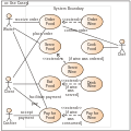
A basic example of an actor in UML can be seen in a use case diagram for an Automated Teller Machine (ATM) system, where the primary actor is the "Customer" who interacts with the system to perform banking transactions.[13] In this scenario, the Customer initiates a cash withdrawal by inserting a card, entering a PIN, and specifying the amount, representing a straightforward external entity driving the system's functionality.[13] The diagram depicts the Customer as a stick-figure icon positioned outside a rectangular boundary that encloses the ATM subsystem, connected by a solid line to an oval-shaped use case labeled "Withdraw Cash" within the boundary.[13] This notation highlights the actor's external role, with the line indicating a direct association where the Customer triggers the use case.[13] Additionally, a secondary actor, the "Bank Database," associates with the "Withdraw Cash" use case via another line to verify account balances and authorize the transaction, illustrating how external systems support the primary interaction without being the initiator.[13] This example demonstrates the fundamental boundary between the system and its actors, emphasizing simple associations that show initiation and support roles essential for introductory UML modeling.[13]Advanced Scenarios
In advanced UML modeling, actor hierarchies enable the representation of specialized roles within broader categories, enhancing reusability and clarity in complex systems. Consider an e-commerce platform where the general "User" actor is specialized into "Buyer" and "Seller" through generalization relationships. The "Buyer" inherits the basic interaction capabilities of "User," such as authentication, while adding specific behaviors like order placement; a generalization arrow points from "Buyer" to "User," indicating inheritance of associations and attributes. Similarly, "Seller" generalizes "User" to include inventory management functions. This structure allows shared use cases, such as "Authenticate User," to be associated with the general actor, while specialized use cases like "Place Order" connect directly to "Buyer" via an association line.[1] Secondary actors, often external systems, further complicate interactions by supporting primary actors across multiple use cases. In the e-commerce example, the "Payment Processor" serves as a secondary actor, handling financial transactions independently of the primary "Buyer." It associates with the "Process Payment" use case through a directed line, typically initiated by the system rather than the actor itself. Multiplicity refines these associations; for instance, a single "Payment Processor" instance (multiplicity 1 on the actor end) can participate in many "Process Payment" instances (multiplicity * on the use case end), reflecting real-world scalability where one gateway supports numerous transactions. This multiplicity is specified at the association ends, ensuring precise modeling of participation constraints.[1][11][14] Such advanced actor configurations find application in modeling distributed architectures like microservices, where external APIs function as actors to represent interactions with third-party services. For example, an external payment API can act as an actor associating with use cases like "Validate Transaction," encapsulating boundary interactions without delving into internal service details. This approach highlights system boundaries, treating APIs as black-box entities that provide or consume value.[15] UML 2.5 supports modeling interactions with external entities like actors through ports in composite structure diagrams, allowing depiction of how they engage with the internal parts of structured classifiers such as subsystems for more granular behavioral analysis. For instance, in a subsystem for order fulfillment, an external "Payment Processor" actor can connect via ports to internal parts, facilitating the specification of subsystem-level interactions without flattening the entire system view. This capability supports hierarchical modeling in large-scale systems, aligning actors with the encapsulation principles of structured classifiers.[1]Related Concepts and Comparisons
Comparison with Use Cases
In UML, actors represent external entities or roles that interact with a system, such as human users, other systems, or hardware devices, while use cases encapsulate the internal behaviors and functionalities provided by the system itself.[6][12] Actors are positioned outside the system's boundary, defining the external perspectives that drive interactions, whereas use cases focus on the observable results and value delivered within the system to those actors or stakeholders.[6][12] The relationship between actors and use cases is one of collaboration and initiation, where actors trigger or participate in use cases through associations, but actors remain separate from the system's implementation details.[12] For instance, an actor may initiate a use case to achieve a goal, but the use case describes the system's response and behavior without incorporating the actor's internal logic.[6] This separation ensures that actors model "who" or "what" interacts with the system, while use cases specify "what" the system does in response.[12] According to the UML 2.5 specification, actors are classifiers external to the subject (the system under consideration), often stereotyped as such to emphasize their role-based nature, whereas use cases are behavioral classifiers that reside within the subject and may not require actor initiation in all cases.[16][12] This distinction highlights actors' scope as interaction initiators or supporters outside the system's boundary, in contrast to use cases' scope as self-contained units of functionality.[6] A common misconception is that actors equate directly to specific users, whereas they actually represent abstract roles that any entity—human or otherwise—may fulfill during interactions.[17] Similarly, use cases are often confused with simple system features, but they instead model complete interaction scenarios yielding value through observable behaviors.[12]Distinction from Other UML Elements
In UML, actors are distinguished from classes primarily by their focus on external behavioral roles rather than internal structural modeling. A class defines the structure of objects within a system, including attributes, operations, and relationships that encapsulate data and behavior for internal entities. In contrast, an actor represents a role played by an external entity—such as a human user, hardware device, or another system—that interacts with the subject system but does not model its internal structure; actors lack attributes and operations, emphasizing only the behavioral interface at the system boundary. Unlike objects or instances, which are runtime realizations of classifiers with specific states, values, and lifecycles, actors do not represent instantiable entities or maintain state within the modeled system. An object is an instance specification that embodies a particular set of values for a classifier's features during execution. Actors, however, abstract roles without instantiation, serving solely to denote external participants in interactions like use cases, without attributes for state or behavior beyond association endpoints. Actors also differ from components, which are structural elements that encapsulate modular parts of a system with provided and required interfaces for both internal and external interactions. Components focus on deployable units of implementation, including realization of behavior through ports and connectors. Actors, by comparison, are purely behavioral classifiers constrained to external contexts, without structural decomposition or interface specifications, highlighting only the role in system-external collaborations. In the UML 2.5 metamodel, actors extend the Classifier metaclass but are specialized as a kind of BehavioredClassifier with constraints limiting their use to external roles; they inherit generalization and association capabilities but are prohibited from owning internal features like methods or properties that apply to system-inherent elements. This metamodel positioning ensures actors remain boundary-focused, unlike classifiers such as classes or components that support internal modeling hierarchies. A key best practice in UML modeling is to reserve actors exclusively for defining system boundaries and external interactions, avoiding their use for internal entities; instead, internal roles or subsystems should be represented using stereotypes on classes, components, or other structural elements to maintain clear separation between external and internal concerns.References
- Below is a merged response that consolidates all the information from the provided summaries of the "Actor" definition in the UML 2.5.1 specification. To retain as much detail as possible in a dense and organized format, I will use a combination of narrative text and tables in CSV format where appropriate. The response includes definitions, semantics, key characteristics, notation, and useful URLs, synthesizing the overlapping and unique details from all segments.