
Community hub
Recent from talks
Contribute something
Nothing was collected or created yet.
Displacement mapping
View on WikipediaThis article needs additional citations for verification. (June 2023) |


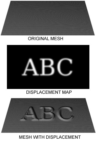
Displacement mapping is an alternative computer graphics technique in contrast to bump, normal, and parallax mapping, using a texture or height map to cause an effect where the actual geometric position of points over the textured surface are displaced, often along the local surface normal, according to the value the texture function evaluates to at each point on the surface.[1] It gives surfaces a sense of depth and detail, permitting in particular self-occlusion, self-shadowing and silhouettes; on the other hand, it is the most costly of this class of techniques owing to the large amount of additional geometry.
For years, displacement mapping was a peculiarity of high-end rendering systems like PhotoRealistic RenderMan, while realtime APIs, like OpenGL and DirectX, were only starting to use this feature. One of the reasons for this is that the original implementation of displacement mapping required an adaptive tessellation of the surface in order to obtain enough micropolygons whose size matched the size of a pixel on the screen.[citation needed]
Meaning of the term in different contexts
[edit]Displacement mapping includes the term mapping which refers to a texture map being used to modulate the displacement strength. The displacement direction is usually the local surface normal. Today, many renderers allow programmable shading which can create high quality (multidimensional) procedural textures and patterns at arbitrarily high frequencies. The use of the term mapping becomes arguable then, as no texture map is involved anymore. Therefore, the broader term displacement is often used today to refer to a super concept that also includes displacement based on a texture map.
Renderers using the REYES algorithm, or similar approaches based on micropolygons, have allowed displacement mapping at arbitrary high frequencies since they became available almost 20 years ago.
The first commercially available renderer to implement a micropolygon displacement mapping approach through REYES was Pixar's PhotoRealistic RenderMan. Micropolygon renderers commonly tessellate geometry themselves at a granularity suitable for the image being rendered. That is: the modeling application delivers high-level primitives to the renderer. Examples include true NURBS- or subdivision surfaces. The renderer then tessellates this geometry into micropolygons at render time using view-based constraints derived from the image being rendered.
Other renderers that require the modeling application to deliver objects pre-tessellated into arbitrary polygons or even triangles have defined the term displacement mapping as moving the vertices of these polygons. Often the displacement direction is also limited to the surface normal at the vertex. While conceptually similar, those polygons are usually a lot larger than micropolygons. The quality achieved from this approach is thus limited by the geometry's tessellation density a long time before the renderer gets access to it.
This difference between displacement mapping in micropolygon renderers vs. displacement mapping in a non-tessellating (macro)polygon renderers can often lead to confusion in conversations between people whose exposure to each technology or implementation is limited. Even more so, as in recent years, many non-micropolygon renderers have added the ability to do displacement mapping of a quality similar to that which a micropolygon renderer is able to deliver naturally. To distinguish between the crude pre-tessellation-based displacement these renderers did before, the term sub-pixel displacement was introduced to describe this feature.[citation needed]
Sub-pixel displacement commonly refers to finer re-tessellation of geometry that was already tessellated into polygons. This re-tessellation results in micropolygons or often microtriangles. The vertices of these then get moved along their normals to achieve the displacement mapping.
True micropolygon renderers have always been able to do what sub-pixel-displacement achieved only recently, but at a higher quality and in arbitrary displacement directions.
Recent developments seem to indicate that some of the renderers that use sub-pixel displacement move towards supporting higher level geometry too. As the vendors of these renderers are likely to keep using the term sub-pixel displacement, this will probably lead to more obfuscation of what displacement mapping really stands for, in 3D computer graphics.
In reference to Microsoft's proprietary High Level Shader Language, displacement mapping can be interpreted as a kind of "vertex-texture mapping" where the values of the texture map do not alter pixel colors (as is much more common), but instead change the position of vertices. Unlike bump, normal and parallax mapping, all of which can be said to "fake" the behavior of displacement mapping, in this way a genuinely rough surface can be produced from a texture. It has to be used in conjunction with adaptive tessellation techniques (that increases the number of rendered polygons according to current viewing settings) to produce highly detailed meshes.[citation needed]
See also
[edit]Further reading
[edit]- Blender Displacement Mapping
- Vray Displacement Mapping
- Relief Texture Mapping website
- Parallax Occlusion Mapping in GLSL on sunandblackcat.com
- Real-Time Relief Mapping on Arbitrary Polygonal Surfaces paper
- Relief Mapping of Non-Height-Field Surface Details paper
- State of the art of displacement mapping on the gpu paper
References
[edit]- ^ "Chapter 8. Per-Pixel Displacement Mapping with Distance Functions". NVIDIA Developer. Retrieved 2023-05-10.
Displacement mapping
View on GrokipediaFundamentals
Definition and Purpose
Displacement mapping is a computer graphics technique that alters the geometry of a 3D surface by shifting vertices or points based on scalar values from a height map or texture, typically displacing them along the direction of the surface normal to add detailed geometric features.[5][6] Introduced in 1984 as an extension within procedural shading systems, it enables the representation of complex surface perturbations directly in the model's structure rather than through visual simulation alone.[7] The primary purpose of displacement mapping is to incorporate high-frequency details, such as cracks, wrinkles, or engravings, onto low-resolution base models without requiring extensive manual sculpting or high-polygon counts, which optimizes memory and computational resources in rendering pipelines.[7][5] By genuinely modifying the surface geometry, it supports advanced lighting interactions, including accurate depth cues, proper occlusions, and self-shadowing that enhance photorealism in both offline and real-time applications.[8] This approach is particularly valuable for scenes demanding intricate environmental details, like terrain or architectural elements, where efficiency in detail addition is crucial.[6] A key benefit of true geometric displacement is its ability to produce visible changes in object silhouettes and enable inter-object shadowing, effects that are unattainable with non-geometric approximations.[8][7] For instance, a grayscale height map can drive the process, with white areas pushing surface points outward to create raised features and black areas pulling them inward for depressions, directly influencing the model's overall form and interaction with light.[9]Principles of Operation
Displacement mapping operates by perturbing the geometry of a base surface using a scalar height field, typically represented as a grayscale texture map known as a height map. A height map encodes displacement amplitudes in its pixel intensities, where brighter values indicate positive displacement (protrusion) and darker values indicate negative displacement (indentation), often normalized to a range such as [0, 1] or [-1, 1] to represent the relative height variation across the surface.[10] Texture sampling occurs at parametric coordinates (u, v) on the base surface to retrieve these height values, commonly using bilinear interpolation for smooth transitions between texels, ensuring the displacement aligns with the underlying texture space.[10] The core process begins with selecting points on the base surface, defined by their original position and interpolated surface normal . At each point, the height map is sampled using the associated texture coordinates to obtain the scalar height value . This value is then scaled by a user-defined displacement factor to control the overall amplitude and added as an offset along the normal direction, effectively modifying the surface geometry to simulate detailed features like bumps or depressions without altering the base mesh topology.[11] The displaced position is computed via the key equation: where is the new vertex position after displacement, is the original position, is the sampled and scaled height, and is the unit normal at the point.[11] This offset ensures the perturbation follows the surface orientation, preserving continuity and avoiding unnatural distortions. Following displacement, the surface normals must be recalculated to accurately reflect the updated geometry for subsequent lighting computations. This is achieved by deriving the partial derivatives of the height field with respect to the texture coordinates, and , which approximate the slopes in the tangent space.[10] These derivatives are typically estimated using finite differences, sampling the height map at neighboring texels around to compute the rate of change—for instance, .[10] The perturbed normal is then obtained by adjusting the original normal with these slope vectors in the tangent-bitangent space and normalizing the result, ensuring proper shading of the displaced features.[1]Comparison to Other Techniques
Bump and Normal Mapping
Bump mapping is a shading technique that simulates the appearance of surface roughness or wrinkles by perturbing the interpolated surface normals during lighting calculations, without altering the underlying geometry.[12] Introduced by James F. Blinn in 1978 to render wrinkled surfaces efficiently, it uses a height map, or bump function , to derive perturbations based on its spatial derivatives.[13] The perturbed normal is computed as , where is the original surface normal and approximates the local slope from the height field.[13] This approach adds visual detail to flat or low-resolution models by modifying how light interacts with the surface in diffuse and specular shading, at a computational cost roughly twice that of basic texture mapping.[13] Normal mapping extends bump mapping by directly storing precomputed normal vectors in an RGB texture, typically in tangent space relative to the surface, to enable more precise lighting simulation on low-polygon models.[14] Developed in the late 1990s as part of appearance-preserving mesh simplification, it transfers detailed normals from high-resolution models to simplified geometry, preserving fine-scale features like grooves or facets without increasing vertex count.[14] The RGB channels encode the normal components (with blue often near 1 for outward-facing perturbations), which are transformed to world or view space during rendering for accurate per-pixel lighting.[14] This method became prominent in real-time applications for its efficiency in faking complex geometry through shading alone. Both bump and normal mapping share key limitations: they affect only lighting computations and produce no actual geometric depth, failing to cast realistic shadows, create occlusions, or alter silhouettes from any viewpoint.[13] As a result, they are best suited for enhancing diffuse and specular effects on surfaces viewed at grazing angles but cannot simulate true three-dimensional structure, unlike displacement mapping, which modifies geometry to address these shortcomings.[13]Parallax and Relief Mapping
Parallax mapping is a technique that simulates the depth and parallax effects of displaced surfaces by perturbing texture coordinates in a view-dependent manner, without modifying the underlying geometry. It relies on a height map, typically stored in the alpha channel of a texture, to offset the sampling location for color and normal data based on the viewer's direction. This creates an illusion of surface unevenness as the viewpoint changes, enhancing the perception of three-dimensional detail on flat polygons. The core operation involves a simple linear approximation of the ray intersection with the height field, given by the formula , where and are the original and offset texture coordinates, is the view vector in tangent space (with ), and is the height value from the map.[15] This method builds upon foundational shading techniques like bump mapping by introducing view-dependent shifts, rather than solely altering surface normals for lighting. Relief mapping extends parallax mapping by employing an iterative ray-marching approach to more accurately trace visibility rays through the height field, allowing for better handling of self-occlusions and steeper surface features. In this process, a ray is cast from the viewer through each pixel toward the surface, stepping along the height field in discrete increments until it intersects the implied geometry defined by the height map; this typically involves 8–32 samples per pixel, with binary search refinements for precision. The algorithm samples the height map repeatedly to find the closest intersection point, enabling the texture coordinates to be adjusted accordingly for color and normal lookup, which results in more convincing depth cues and reduced artifacts from under-sampling steep angles. Unlike the single-offset computation in basic parallax mapping, relief mapping's iterative nature better approximates true ray-height field intersections, making it suitable for complex surfaces with overhangs.[16] Both techniques differ fundamentally from true displacement mapping, as they operate entirely in screen space as pixel-based illusions that do not alter vertex positions or tessellate geometry, thereby avoiding the high computational cost of full 3D surface deformation. This makes them computationally efficient for real-time applications—relief mapping, for instance, achieves interactive frame rates on early 2000s GPUs with minimal additional overhead beyond texture fetches—while true displacement requires substantial polygon subdivision and rasterization resources. However, these methods are prone to artifacts such as incorrect silhouettes, where displaced features do not cast proper shadows or clip against the base geometry, and they fail to support multi-layer depth or accurate global illumination interactions. Parallax mapping offers speed but limited accuracy for occlusions, whereas relief mapping provides superior fidelity at the expense of more samples, though both remain approximations unsuitable for extreme close-ups without additional refinements.[15][16] In practice, parallax and relief mapping have been widely adopted in video games to add fine details to terrain and architectural surfaces prior to the ubiquity of hardware tessellation.Implementation Methods
Offline Rendering Approaches
In offline rendering systems, displacement mapping is prominently implemented through micropolygon-based approaches, such as the REYES algorithm employed in Pixar's RenderMan. The REYES pipeline processes geometric primitives by first splitting them into bounded regions and then dicing these into micropolygons—small, flat-shaded quadrilaterals typically sized at about one-half pixel in screen space—to enable precise surface evaluation.[17] This subdivision occurs adaptively, guided by estimates of the primitive's projected screen-space extent, ensuring that finer details are captured where necessary without excessive computation elsewhere. Displacement is then applied during the shading stage, perturbing the positions of micropolygon vertices along surface normals based on a scalar height field derived from texture maps or procedural functions, which alters both geometry and shading normals for enhanced realism.[17] Integration with subdivision surfaces further extends displacement mapping's capabilities in offline renderers, allowing application to smooth base meshes like NURBS patches or Catmull-Clark subdivision surfaces to model organic, high-detail forms. In this framework, the base surface is first subdivided to generate a limit surface, upon which displacement offsets are computed and applied, often using a unified subdivision scheme for both the domain geometry and the displacement field itself.[18] Adaptive tessellation refines the mesh based on screen-space error metrics, such as projected area or curvature, to balance detail and efficiency; height map offsets are then evaluated at subdivided points, supporting both scalar displacements from images and procedural variations for complex patterns. This process enables compact representation of intricate details, as the control mesh remains coarse while displacements add fine-scale geometry.[18] In production environments like film rendering, these techniques yield high-fidelity results for elements such as detailed skin textures or rugged terrain, where RenderMan's displacement shaders combine with subdivision bases to produce lifelike wrinkles, pores, or rocky formations without manual modeling of every feature.[19] For instance, photorealistic character heads in animations leverage layered displacement maps on subdivided meshes to achieve subsurface scattering-compatible geometry, while terrain scenes benefit from procedural displacements that simulate natural erosion and vegetation displacement.[19]Real-Time Graphics Techniques
Real-time displacement mapping in interactive graphics leverages GPU hardware acceleration to dynamically generate and modify geometry, enabling high-fidelity surface details without excessive preprocessing or memory usage.[20] Modern APIs such as DirectX 11 and OpenGL 4.0 introduced tessellation stages that allow for on-the-fly subdivision of base meshes, followed by displacement application to simulate complex surfaces like terrain or organic models in real time.[21] This approach contrasts with static meshes by adapting detail levels based on viewport proximity, maintaining interactive frame rates on consumer hardware.[22] Tessellation shaders form the core of these techniques, utilizing hull shaders to compute patch density and domain shaders to evaluate and displace vertices. In DirectX 11, the hull shader outputs control points and tessellation factors for the fixed-function tessellator, which generates a finer grid; the domain shader then samples a height map—typically a grayscale texture representing surface elevations—and offsets vertex positions along the surface normal to apply displacement.[20] OpenGL 4.0 mirrors this pipeline with equivalent tessellation control and evaluation shaders, enabling similar texture-based lookups in the evaluation stage for vertex displacement.[23] This process occurs entirely on the GPU, supporting animated models with millions of effective triangles at 60 frames per second or higher on mid-range hardware.[1] Displacement can be applied at the per-vertex level for broader, coarser details or per-pixel level for finer resolution, each with distinct trade-offs in quality and performance. Per-vertex displacement, performed in the domain or vertex shader, modifies geometry at subdivided points using height map samples, providing true surface occlusion but requiring sufficient tessellation density to avoid visible cracks along edges where adjacent patches differ in height.[24] Per-pixel approaches, often using distance functions in fragment shaders, approximate displacement by ray-marching against the height field from the pixel's view direction, achieving sub-texel detail without geometry changes but introducing risks like cracking artifacts from inconsistent depth interpolation across shared edges.[2] To maintain performance, optimizations focus on level-of-detail (LOD) selection and adaptive tessellation schemes that vary subdivision based on screen-space factors. Screen-space adaptive tessellation computes edge lengths in projected pixels to determine tessellation factors dynamically, reducing over-tessellation for distant surfaces while preserving detail for closer ones, often combined with conservative rasterization to prevent popping.[25] LOD selection integrates mipmapped height maps to match displacement resolution to the base mesh density, ensuring balanced geometry generation that sustains frame rates above 30 FPS even for large scenes like procedural terrains.[26] NVIDIA's techniques in the GPU Gems series exemplify parallax-corrected displacement for enhanced realism in real-time shaders. For instance, per-pixel methods using distance functions in GPU Gems 2 enable parallax occlusion by tracing rays against a 3D distance field derived from height maps, correcting view-dependent distortions without full geometry tessellation.[2] These approaches, extended in later works, integrate with tessellation for hybrid vertex-pixel pipelines, as seen in relief mapping variants that approximate displacement silhouettes with reduced aliasing.[27]Advanced Variations
Vector Displacement Mapping
Vector displacement mapping extends traditional scalar displacement techniques by encoding displacement as a vector field, typically in tangent space, allowing vertices to be offset in arbitrary three-dimensional directions rather than solely along the surface normal. This approach utilizes RGB texture channels to store the X, Y, and Z components of the displacement vector, enabling the representation of complex surface features that deviate significantly from the base geometry. Unlike scalar methods, which are limited to height-based perturbations and can produce artifacts on curved or tilted surfaces, vector displacement supports multi-directional shifts that align with the detailed sculpt of a high-resolution model.[28] The core operation of vector displacement mapping can be expressed aswhere is the original vertex position, is the displaced position, and is the displacement vector sampled from the texture at coordinates . This vector is derived from the RGB values of the map, often normalized and scaled to match the desired detail level, and is typically computed in tangent space to ensure compatibility with deformed or animated geometry. The use of tangent space maintains the displacement's orientation relative to the surface's local frame, preventing distortions during model transformations.[29] One key advantage of vector displacement mapping is its ability to handle overhangs, undercuts, and intricate topologies—such as fur, scales, or interlocking structures—without the self-intersection issues common in scalar displacement, where offsets are constrained to the normal direction and may cause geometric overlaps on non-planar surfaces. This flexibility allows for more accurate reproduction of high-fidelity details from sculpting workflows, reducing the need for additional normal or parallax maps to simulate depth illusions. Furthermore, vector maps support 32-bit floating-point formats, which provide greater precision and eliminate the requirement for manual depth adjustments, enhancing rendering efficiency in supported pipelines.[28] Vector displacement maps are commonly created by baking the positional differences between a high-resolution sculpted mesh and its lower-resolution base counterpart, often using specialized digital sculpting tools. In software like ZBrush, this process involves selecting the tool's Vector Displacement Map sub-palette, configuring settings such as tangent space orientation and bit depth (16-bit or 32-bit), and exporting the result as a TIFF or OpenEXR file. The baking computes the vector offset for each texel by subtracting the projected high-poly positions from the low-poly base, ensuring the map captures fine details like cavities or protrusions that scalar height maps cannot represent directionally. This method integrates seamlessly with rendering engines in applications such as Maya or 3ds Max, where the map drives true geometric subdivision during tessellation.[28][30] Recent advances as of 2025 include AI-driven methods for generating vector displacement maps from single images or text prompts, enabling non-experts to create detailed geometric stamps for 3D modeling without manual sculpting. For example, GenVDM synthesizes VDMs from images using diffusion models, while Text2VDM allows text-to-VDM generation for expressive, interactive applications.[31][32]