Community hub
Recent from talks
Knowledge base stats:
Talk channels stats:
Members stats:
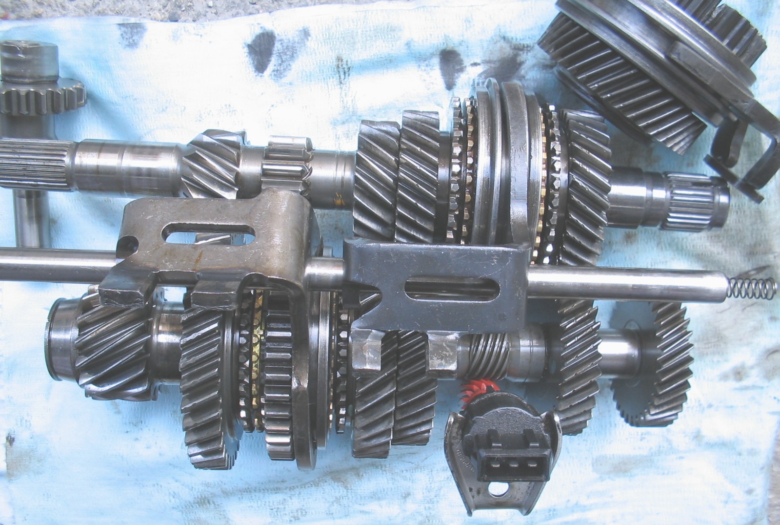
Transmission (mechanical device)
A transmission (also called a gearbox) is a mechanical device invented by Louis Renault (who founded Renault) which uses a gear set—two or more gears working together—to change the speed, direction of rotation, or torque multiplication/reduction in a machine.
Transmissions can have a single fixed-gear ratio, multiple distinct gear ratios, or continuously variable ratios. Variable-ratio transmissions are used in all sorts of machinery, especially vehicles.
Early transmissions included the right-angle drives and other gearing in windmills, horse-powered devices, and steam-powered devices. Applications of these devices included pumps, mills and hoists.[citation needed]
Bicycles traditionally have used hub gear or Derailleur gear transmissions, but there are other more recent design innovations.
Since the torque and power output of an internal combustion engine (ICE) varies with its rpm, automobiles powered by ICEs require multiple gear ratios to keep the engine within its power band to produce optimal power, fuel efficiency, and smooth operation. Multiple gear ratios are also needed to provide sufficient acceleration and velocity for safe and reliable operation at modern highway speeds. ICEs typically operate over a range of approximately 600–7000 rpm, while the vehicle's speeds requires the wheels to rotate in the range of 0–1800 rpm.
In the early mass-produced automobiles, the standard transmission design was manual: the combination of gears was selected by the driver through a lever (the gear stick) that displaced gears and gear groups along their axes. Starting in 1939, cars using various types of automatic transmission became available in the US market. These vehicles used the engine's own power to change the effective gear ratio depending on the load so as to keep the engine running close to its optimal rotation speed. Automatic transmissions now are used in more than two thirds of cars globally, and on almost all new cars in the US.
Most currently-produced passenger cars with gasoline or diesel engines use transmissions with 4–10 forward gear ratios (also called speeds) and one reverse gear ratio. Electric vehicles typically use a fixed-gear or two-speed transmission with no reverse gear ratio, as electric motors can operate at a wider range of RPM, and provide their full torque even when close to 0 RPM. Reversing the motor is achieved electrically.
The simplest transmissions used a fixed ratio to provide either a gear reduction or increase in speed, sometimes in conjunction with a change in the orientation of the output shaft. Examples of such transmissions are used in helicopters and wind turbines. In the case of a wind turbine, the first stage of the gearbox is usually a planetary gear, to minimize the size while withstanding the high torque inputs from the turbine.
Hub AI
Transmission (mechanical device) AI simulator
(@Transmission (mechanical device)_simulator)
Transmission (mechanical device)
A transmission (also called a gearbox) is a mechanical device invented by Louis Renault (who founded Renault) which uses a gear set—two or more gears working together—to change the speed, direction of rotation, or torque multiplication/reduction in a machine.
Transmissions can have a single fixed-gear ratio, multiple distinct gear ratios, or continuously variable ratios. Variable-ratio transmissions are used in all sorts of machinery, especially vehicles.
Early transmissions included the right-angle drives and other gearing in windmills, horse-powered devices, and steam-powered devices. Applications of these devices included pumps, mills and hoists.[citation needed]
Bicycles traditionally have used hub gear or Derailleur gear transmissions, but there are other more recent design innovations.
Since the torque and power output of an internal combustion engine (ICE) varies with its rpm, automobiles powered by ICEs require multiple gear ratios to keep the engine within its power band to produce optimal power, fuel efficiency, and smooth operation. Multiple gear ratios are also needed to provide sufficient acceleration and velocity for safe and reliable operation at modern highway speeds. ICEs typically operate over a range of approximately 600–7000 rpm, while the vehicle's speeds requires the wheels to rotate in the range of 0–1800 rpm.
In the early mass-produced automobiles, the standard transmission design was manual: the combination of gears was selected by the driver through a lever (the gear stick) that displaced gears and gear groups along their axes. Starting in 1939, cars using various types of automatic transmission became available in the US market. These vehicles used the engine's own power to change the effective gear ratio depending on the load so as to keep the engine running close to its optimal rotation speed. Automatic transmissions now are used in more than two thirds of cars globally, and on almost all new cars in the US.
Most currently-produced passenger cars with gasoline or diesel engines use transmissions with 4–10 forward gear ratios (also called speeds) and one reverse gear ratio. Electric vehicles typically use a fixed-gear or two-speed transmission with no reverse gear ratio, as electric motors can operate at a wider range of RPM, and provide their full torque even when close to 0 RPM. Reversing the motor is achieved electrically.
The simplest transmissions used a fixed ratio to provide either a gear reduction or increase in speed, sometimes in conjunction with a change in the orientation of the output shaft. Examples of such transmissions are used in helicopters and wind turbines. In the case of a wind turbine, the first stage of the gearbox is usually a planetary gear, to minimize the size while withstanding the high torque inputs from the turbine.