Hubbry Logo
T-antennaT-antennaMain
Open search
T-antenna
Community hub
T-antenna
logo
8 pages, 0 posts
0 subscribers
Be the first to start a discussion here.
T-antenna
T-antenna
from Wikipedia

A 1935 photo of WOR / 710AM's facility in Carteret, New Jersey. In this case there are three radiators: the two towers and the center ‘T’-antenna, suspended in the middle.
An amateur homebuilt inverted-L antenna

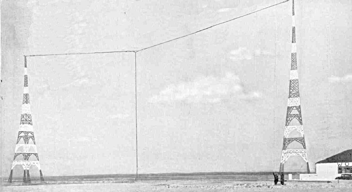
A ‘T’-antenna, ‘T’-aerial, or flat-top antenna is a monopole radio antenna consisting of one or more horizontal wires suspended between two supporting radio masts or buildings and insulated from them at the ends.[1][2] A vertical wire is connected to the center of the horizontal wires and hangs down close to the ground, connected to the transmitter or receiver. The shape of the antenna resembles the letter "T", hence the name. The transmitter power is applied, or the receiver is connected, between the bottom of the vertical wire and a ground connection.[1]

A closely related antenna is the inverted-L antenna. This is similar to the T-antenna except that the vertical feeder wire, instead of being attached to the center of the horizontal topload wires, is attached at one end. The name comes from its resemblance to an inverted letter "L" (Γ). The T-antenna is an omnidirectional antenna, radiating equal radio power in all azimuthal directions, while the inverted-L is a weakly directional antenna, with maximum radio power radiated in the direction of the top load wire, off the end with the feeder attached.

Multiwire broadcast T-antenna of early AM station WBZ, in Springfield, MA, 1925.

'T'- and inverted-L antennas are typically used in the VLF, LF, MF, and shortwave bands,[3][4]: 578–579 [2] and are widely used as transmitting antennas for amateur radio stations,[5] and long wave and medium wave AM broadcasting stations. They can also be used as receiving antennas for shortwave listening. They function as monopole antennas with capacitive top-loading; other antennas in this category include the umbrella, and triatic antennas. They were invented during the first decades of radio, in the wireless telegraphy era, before 1920.

How it works

[edit]

The 'T'-type antenna is most easily understood as having three functional parts:

Top load
The horizontal wire top section (sometimes called the capacitance hat) acts like a plate of a capacitor.
Radiator
The vertical wire that carries current from the feedpoint at the base to the top; unbalanced current in the vertical segment generates the emitted radio waves.
Ground system
Either wires buried in the ground under the antenna or sometimes wires suspended a few feet above ground (a counterpoise) acts like the other plate of the capacitor.

The wires of the top load are often arranged symmetrically; currents flowing in the oppositely directed symmetrical wires of the top hat cancel each others' fields and so produce no net radiation, with the same cancellation happening in the same way in the ground system. In principle, the capacitance hat (top hat) and its counterpart ground system (counterpoise) could be built to be mirror images of each other. However the ease of just laying wires on the ground or raised a few feet above the soil, as opposed to the practical challenge of supporting top hat's horizontal wires up high, at the apex of the vertical section, typically means that the top hat is usually not built as large as the counterpoise. Further, any electric fields that reach the ground before they are intercepted by the counterpoise will waste energy warming the soil, whereas stray electric fields high in the air will merely spread out a bit more into loss-free open air, before they eventually reach the wires of the top hat.


The top and ground sections effectively function as oppositely charged reservoirs for augmented storage of excess or deficit electrons, more than what could be stored along the top end of the same height bare headed vertical wire. A greater stored charge causes greater current to flow through the vertical segment between the top and base, and that current in the vertical segment produces the radiation emitted by the T-antenna.

Capacitance 'hat'

[edit]
RF current distributions (red) in a vertical monopole antenna "a" and the ‘T’-antenna "b", showing how the horizontal wire serves to improve the efficiency of the vertical radiating wire.[6] The width of the red area perpendicular to the wire at any point is proportional to the current.[a]

The left and right sections of horizontal wire across the top of the 'T' carry equal but oppositely-directed currents. Therefore, far from the antenna, the radio waves radiated by each wire are 180° out of phase with the waves from the other wire, and tend to cancel. There is a similar cancellation of radio waves reflected from the ground. Thus the horizontal wires radiate (almost) no radio power.[4]: 554 

Instead of radiating, the horizontal wires increase the capacitance at the top of the antenna. More current is required in the vertical wire to charge and discharge this added capacitance during the RF oscillation cycle.[6][4]: 554  The increased currents in the vertical wire (see drawing at right) effectively increase the antenna's radiation resistance and thus the RF power radiated.[6]

The top-load capacitance increases as more wires are added, so several parallel horizontal wires are often used, connected together at the center where the vertical wire attaches.[5] Because each wire's electric field impinges on those of adjacent wires, the additional capacitance from each added wire diminishes.[5]

Efficiency of capacitive top loading

[edit]

The horizontal top load wire can increase radiated power by 2 to 4 times (3 to 6 dB) for a given base current.[6] Consequently the 'T'-antenna can radiate more power than a simple vertical monopole of the same height. Similarly, a receiving T-antenna can intercept more power from the same incoming radio wave signal strength than the same height vertical antenna can.

In antennas built for frequencies near or below 600 kHz[b], the length of an antenna's wire segments is usually shorter than a quarter wavelength[c] [  1 /4λ ≈ 125 m (410 feet)[c] at 600 kHz[b]], the shortest length of unloaded straight wire that achieves resonance.[5] In this circumstance, a ‘T’-antenna is a capacitively top-loaded, electrically short, vertical monopole.[4]: 578–579 

Despite its improvements over a short vertical, the typical ‘T’-antenna is still not as efficient as a full-height  1 /4λ[c] vertical monopole,[5] and has a higher Q and thus a narrower bandwidth. 'T'-antennas are typically used at low frequencies where building a full-size quarter-wave high vertical antenna is not practical,[2][7] and the vertical radiating wire is often very electrically short: Only a small fraction of a wavelength long, 1/10λ or less. An electrically short antenna has a base reactance that is capacitive, and although capacitive loading at the top does reduce capacitive reactance at the base, usually some residual capacitive reactance remains. For transmitting antennas that must be tuned-out by added inductive reactance from a loading coil, so the antenna can be efficiently fed power.

Types of 'T' antennas: (A) simple, (B) multiwire (flattop), (C) cage.
Types of inverted L antennas: (D) simple, (E) multiwire (flattop) (G) cage.
Red parts are insulators, brown are supporting masts. The feedline to the transmitter or receiver is connected at F. The multiwire toploads used in B,C,E, and G increase capacitance to ground and thus radiation resistance and output power, they are often used as transmitting antennas. The cage construction C and G equalizes current in the wires, reducing resistance

Radiation pattern

[edit]

Since the vertical wire is the actual radiating element, the antenna radiates vertically polarized radio waves in an omnidirectional radiation pattern, with equal power in all azimuthal directions.[8] The axis of the horizontal wire makes little difference. The power is maximum in a horizontal direction or at a shallow elevation angle, decreasing to zero at the zenith. This makes it a good antenna at LF or MF frequencies, which propagate as ground waves with vertical polarization, but it also radiates enough power at higher elevation angles to be useful for sky wave ("skip") communication. The effect of poor ground conductivity is generally to tilt the pattern up, with the maximum signal strength at a higher elevation angle.

Transmitting antennas

[edit]

In the longer wavelength ranges where 'T'-antennas are typically used, the electrical characteristics of antennas are generally not critical for modern radio receivers; reception is limited by natural noise, rather than by the signal power gathered by the receiving antenna.[5]

Transmitting antennas are different, and feedpoint impedance[d] is critical: The combination of reactance and resistance at the antenna feedpoint must be matched to the impedance of the feedline, and beyond it, the transmitter's output stage. If mismatched, current sent from the transmitter to the antenna will reflect back down the feedline from the antenna, creating a condition called standing waves on the line. This reduces the power radiated by the antenna, and at worst may damage the transmitter.

Reactance

[edit]

Any monopole antenna that is shorter than  1 / 4 wave has a capacitive reactance; the shorter it is, the higher that reactance, and the greater the proportion of the feed current that will be reflected back towards the transmitter. To efficiently drive current into a short transmitting antenna it must be made resonant (reactance-free), if the top section has not already done so. The capacitance is usually canceled out by an added loading coil or its equivalent; the loading coil is conventionally placed at the base of the antenna for accessibility, connected between the antenna and its feedline.

One of the first uses of 'T' aerials in the early 20th century was on ships, since they could be strung between masts. This is the antenna of RMS Titanic, which broadcast the distress call during her sinking in 1912. It was a multiwire 'T' with a 50-metre (160 ft) vertical wire and four 120-metre (400 ft) horizontal wires.

The horizontal top section of a 'T'-antenna can also reduce the capacitive reactance at the feedpoint, substituting for a vertical section whose height would be about  2 / 3  its length;[9] if it is long enough, it completely eliminates reactance and obviates any need for a loading coil at the feedpoint.

At medium and low frequencies, the high antenna capacitance and the high inductance of the loading coil, compared to the short antenna’s low radiation resistance, makes the loaded antenna behave like a high Q tuned circuit, with a narrow bandwidth over which it will remain well matched to the transmission line, when compared to a  1 / 4 λ monopole.[c]

To operate over a large frequency range the loading coil often must be adjustable and adjusted when the frequency is changed to limit the power reflected back towards the transmitter. The high Q also causes a high voltage on the antenna, which is maximum at the current nodes at the ends of the horizontal wire, roughly Q times the driving-point voltage. The insulators at the ends must be designed to withstand these voltages. In high power transmitters the output power is often limited by the onset of corona discharge from the wires.[10]

Resistance

[edit]

Radiation resistance is the equivalent resistance of an antenna due to its radiation of radio waves; for a full-length quarter-wave monopole the radiation resistance is around 25 ohms.[citation needed] Any antenna that is short compared to the operating wavelength has a lower radiation resistance than a longer antenna; sometimes catastrophically so, far beyond the maximum performance improvement provided by a T-antenna. So at low frequencies, even a 'T'-antenna can have very low radiation resistance, often less than 1 ohm,[5][11] so the efficiency is limited by other resistances in the antenna and the ground system. The input power is divided between the radiation resistance and the 'ohmic' resistances of the antenna+ground circuit, chiefly the coil and the ground. The resistance in the coil and particularly the ground system must be kept very low to minimize the power dissipated in them.

It can be seen that at low frequencies the design of the loading coil can be challenging:[5] it must have high inductance but very low losses at the transmitting frequency (high Q), must carry high currents, withstand high voltages at its ungrounded end, and be adjustable.[7] It is often made of litz wire.[7]

At low frequencies the antenna requires a good low resistance ground to be efficient. The RF ground is typically constructed as a star of many radial copper cables buried about 30 cm (1 foot) in the earth, extending out from the base of the vertical wire, and connected together at the center. The radials should ideally be long enough to extend beyond the displacement current region near the antenna. At VLF frequencies the resistance of the soil becomes a problem, and the radial ground system is usually raised and mounted a few feet above ground, insulated from it, to form a counterpoise.

Equivalent circuit

[edit]
An amateur radio cage 'T'-antenna 18-metre-high (60 ft) by 27-metre-long (90 ft) built in 1922, owned by the Historic Radio Engineers Club, Riverhead, New York. The conductor is made of a 'cage' of 6 wires held apart by wooden spreaders. This antenna achieved transatlantic contacts on 1.5 MHz, at a power of 440 W.
Cage inverted-L antenna of radio amateur Leroy Moffat, Jr, 5HK at his home in Oklahoma City, Oklahoma, USA, in 1922.

The power radiated (or received) by any electrically short vertical antenna, like the 'T'-antenna, is proportional to the square of the effective height of the antenna,[5] so the antenna should be made as high as possible. Without the horizontal wire, the RF current distribution in the vertical wire would decrease very nearly linearly to zero at the top (see drawing "a" above), giving an effective height of half the physical height of the antenna. With an ideal "infinite capacitance" top load wire, the current in the vertical would be constant along its length, giving an effective height equal to the physical height, therefore increasing the radiated power fourfold for the same feed voltage. So the power radiated (or received) by a 'T'-antenna lies between a vertical monopole of the same height and up to four times that.

The radiation resistance of an ideal T-antenna with very large top load capacitance is[6]

so the radiated power is

where

h is the height of the antenna,
λ is the wavelength, and
I0 is the RMS input current in amperes.

This formula shows that the radiated power depends on the product of the base current and the effective height, and is used to determine how many metre-amps are required to achieve a given amount of radiated power.

The equivalent circuit of the antenna (including loading coil) is the series combination of the capacitive reactance of the antenna, the inductive reactance of the loading coil, and the radiation resistance and the other resistances of the antenna-ground circuit. So the input impedance is

where

RC is the Ohmic resistance of the antenna conductors (copper losses)
RD is the equivalent series dielectric losses
Rℓ.c. is the series resistance of the loading coil
RG is the resistance of the ground system
RR is the radiation resistance
Cant. is the apparent capacitance of the antenna at the input terminals
Lℓ.c. is the inductance of the loading coil.

At resonance the capacitive reactance of the antenna is cancelled by the loading coil so the input impedance at resonance Z0 is just the sum of the resistances in the antenna circuit[12]

The efficiency of the antenna at resonance, η, is the ratio of radiated power to input power from the feedline. Since power dissipated as radiation or as heat is proportional to resistance, the efficiency is given by

1.9-kilometre (1.2-mile) multiple-tuned flattop antenna of the historic 17 kHz Grimeton VLF transmitter, Sweden

It can be seen that, since the radiation resistance is usually very low, the major design problem is to keep the other resistances in the antenna-ground system low to obtain the highest efficiency.[12]

Multiple-tuned antenna

[edit]

The multiple-tuned flattop antenna is a variant of the 'T'-antenna used in high-power low-frequency transmitters to reduce ground power losses.[7] It consists of a long capacitive top-load consisting of multiple parallel wires supported by a line of transmission towers, sometimes several miles long. Several vertical radiator wires hang down from the top load, each attached to its own ground through a loading coil. The antenna is driven either at one of the radiator wires or more often at one end of the top load, by bringing the wires of the top load diagonally down to the transmitter.[7]

Although the vertical wires are separated, the distance between them is small compared to the length of the LF waves, so the currents in them are in phase and they can be considered as one radiator. Since the antenna current flows into the ground through N parallel loading coils and grounds rather than one, the equivalent loading coil and ground resistance, and therefore the power dissipated in the loading coil and ground, is reduced to 1/N that of a simple 'T'antenna.[7] The antenna was used in the powerful radio stations of the wireless telegraphy era but has fallen out of favor due to the expense of multiple loading coils.

See also

[edit]

Footnotes

[edit]

References

[edit]
Revisions and contributorsEdit on WikipediaRead on Wikipedia
from Grokipedia
A , also known as a T-aerial or flat-top antenna, is a capacitively top-loaded monopole radio antenna consisting of a vertical radiator connected at its upper end to one or more horizontal wires suspended between supporting masts or towers, forming the characteristic "T" shape. This configuration provides capacitive loading that increases the antenna's effective and , enabling efficient operation at low and medium frequencies (LF and MF bands) where a full quarter-wavelength vertical would be impractically tall. The horizontal element, or "capacity hat," primarily serves to enhance current distribution along the vertical wire rather than contributing significantly to radiation, resulting in a predominantly vertical polarization. T-antennas are widely employed in AM radio broadcasting and other LF/MF transmission systems, where they function as base-fed structures often integrated into self-supporting towers, guyed masts, or wire-supported setups. Their is typically omnidirectional in the horizontal plane—assuming the horizontal radiator's length is short compared to the operating —making them suitable for non-directional coverage over large areas via ground-wave . In broadcasting applications, they can form part of directional arrays by combining multiple vertical radiators with passive reflecting elements to shape coverage toward specific service areas while minimizing interference. Efficiency is further optimized through a well-designed , such as radial wires, to reduce losses in the near-field. Developed in the early during the pioneering era of , the T-antenna evolved as a practical solution for maritime and long-distance communication, where central lead-in connections facilitated omnidirectional performance on ships and fixed stations. By the , it had become a standard design for high-power transmitters, with variations including cage-like horizontal sections for added and mechanical stability. Today, T-antennas remain relevant in legacy infrastructure.

Design and Configuration

Basic Structure

The T-antenna is a characterized by a vertical radiator connected at its apex to a horizontal wire or set of wires forming a "T" configuration, often suspended between two supporting masts and paired with a ground system or counterpoise to complete the electrical circuit. This design allows for efficient operation at lower frequencies where full-size antennas would be impractical due to height constraints. Key components of the standard T-antenna include the vertical wire, which acts as the primary radiating element and is typically shorter than a quarter-wavelength; horizontal top-load wires, which can be a single wire or multiple parallel wires extending from the top of the vertical section; a feedpoint located at the base of the vertical wire for connection to the transmitter; and a radial ground system consisting of buried or elevated wires to provide a low-loss return path for currents. The vertical is often constructed from a single wire or tube, while the top-load wires are insulated and stretched taut to minimize sag. Variants of the T-antenna include the simple T design with a single horizontal wire, multi-wire top hats using several parallel conductors for greater surface area, and cage-style configurations where multiple radial wires extend outward from the top like spokes to enhance loading. These adaptations allow flexibility in deployment, such as on ships or broadcast towers. The T-antenna originated in the early , with a foundational for the top-loaded vertical design granted to Simon Eisenstein in 1909. A prominent early implementation was the multi-wire T-antenna on the RMS Titanic, completed in 1912, which featured four parallel horizontal wires spanning approximately 415 feet and vertical feed wires approximately 120 feet (37 meters) long, dropping from the horizontal wires to the antenna trunk atop the radio room. For low-frequency applications, such as the medium-frequency (MF) band around 600 kHz, the vertical height of a T-antenna is commonly 0.1 to 0.25 , equating to roughly 50 to 125 meters given a wavelength of 500 meters at that . The horizontal top-load wires are dimensioned to provide sufficient , often extending 0.05 to 0.1 wavelengths on each side. The top hat element primarily serves to increase the antenna's effective .

Capacitive Top Hat

The capacitive top hat of a T-antenna is constructed from horizontal wires or rods that extend symmetrically from the top of the vertical , forming the crossbar of the T configuration. These elements are typically arranged in a multi-wire setup, such as a cross or wagon-wheel pattern with 4 to 6 spokes connected by a peripheral wire, using materials like aluminum tubing for durability. In some implementations, the top hat spans diameters of several feet, such as 7 feet in example HF designs or larger scales for lower frequencies to achieve adequate loading. This serves as a element that stores near the antenna's apex, thereby increasing the effective of the without requiring additional vertical extension. By concentrating the in this manner, it enables the overall antenna to function as if it were taller physically, which is particularly beneficial in installations where height is limited. Key design considerations for the involve optimizing wire spacing and configuration to maximize per unit area; closer spacing in multi-wire arrangements enhances the total while minimizing material use. For LF and MF applications, typical values range from hundreds of picofarads, such as 790–815 pF in a documented T-antenna operating at 100–300 kHz. The capacitive provides significant advantages in space-constrained environments by allowing a substantial reduction in the physical height of the vertical compared to an equivalent unloaded monopole, often enabling efficient operation at fractions of a quarter-wavelength. In cage-style top hats, multiple parallel wires are arranged around the vertical element to form a cylindrical structure, promoting uniform distribution across the loading surface and further improving capacitive effectiveness.

Operating Principles

Mechanism of Operation

The T-antenna operates as a top-loaded vertical monopole where the capacitive serves as the primary mechanism to enhance performance, particularly for electrically short antennas with height hλ/4h \ll \lambda/4. The provides capacitive loading that counteracts the inherent capacitive reactance of the shortened vertical section, increasing the effective and enabling the antenna to achieve and approximate the behavior of a full quarter-wave monopole. This compensation allows for a near-uniform current distribution along the vertical , which is crucial for efficient energy transfer from the transmitter to the radiated field. Without top loading, the current would taper significantly, reducing effectiveness, but the capacitive loading maintains higher base currents, optimizing the antenna for low-frequency applications where physical height is limited. In operation, radiofrequency (RF) current flows upward through the vertical wire from the base feed point, charging the top hat and establishing a voltage antinode at its extremities. The reaches its maximum at the top hat, while the current achieves its maximum at the base, creating a pattern that facilitates efficient power delivery. occurs predominantly from the vertical section due to its asymmetric current distribution relative to the , producing vertically polarized waves suitable for long-distance communication. The horizontal wires of the top hat, however, experience symmetric currents flowing in opposite directions, leading to complete cancellation of their far-field contributions and ensuring negligible interference with the overall pattern. To function effectively, the T-antenna requires prerequisite tuning at the operating , typically accomplished via a matching network or base to eliminate residual reactance and achieve a purely resistive . This condition is essential for maximizing power transfer and minimizing losses in the feed system, particularly in electrically short configurations where the top loading alone may not fully compensate for the capacitive nature of the structure. By relying on top loading, the T-antenna thus bridges the gap between practical size constraints and ideal quarter-wave performance, making it a staple in medium-wave and setups.

Efficiency of Top Loading

The top hat in a T-antenna significantly enhances compared to a short vertical monopole without loading, primarily by increasing the and allowing for a higher base current under the same applied voltage, which can boost radiated power by 2 to 4 times (equivalent to 3 to 6 dB gain). This improvement arises because the capacitive top hat alters the current distribution along the vertical element, making it more uniform and thereby elevating the effective electrical height of the antenna. For instance, in medium-frequency applications around 120 kHz, capacitive top loading combined with loading has been shown to achieve up to 4.5 times the radiated power relative to an unloaded short antenna. A key factor in this efficiency gain is the reduction of ground losses, as the top hat concentrates current more effectively near the base while minimizing ohmic losses in the feeding system; the approximate radiated power can be expressed as P53(4πhI0λ)2P \approx \frac{5}{3} \left( \frac{4\pi h I_0}{\lambda} \right)^2, where hh is the , I0I_0 is the base current, and λ\lambda is the . This formula highlights how the top hat's influence on I0I_0 and the effective height contributes to greater power transfer to the radiated field. Additionally, for electrically short antennas (h<λ/4h < \lambda/4), the overall is given by ηRRRR+Rloss\eta \approx \frac{R_R}{R_R + R_\text{loss}}, where top loading increases RRR_R relative to losses from ground systems and loading coils, thereby minimizing the impact of RlossR_\text{loss}. At very low frequencies (VLF) and low frequencies (LF), such as 17 kHz, optimized T-antennas with top hats can achieve efficiencies of 50-80%, a substantial improvement over unloaded short verticals, which typically exhibit efficiencies below 10% due to their low radiation resistance (e.g., around 0.9% for a 300 ft tower at 20 kHz). For example, a top-loaded T-antenna operating at 15.525 kHz has demonstrated an efficiency of approximately 76% with a radiation resistance of 0.142 ohms and controlled loss resistance. However, this efficiency comes with the drawback of a higher quality factor (Q), which results in narrower bandwidth and necessitates precise tuning to maintain performance across the operating frequency.

Radiation Characteristics

Radiation Pattern

The T-antenna produces a radiation pattern that is omnidirectional in the azimuthal plane, delivering uniform power distribution across all horizontal directions, while radiating vertically polarized electromagnetic waves. This configuration arises from the symmetric vertical monopole structure, which ensures equal field strength in the horizontal plane regardless of azimuth angle. The elevation pattern closely resembles that of a short monopole over ground, featuring a low-angle lobe that peaks near the horizon to facilitate effective ground-wave propagation. Key features of the pattern include maximum radiation directed horizontally toward the horizon, accompanied by nulls directly overhead, which minimize energy loss to the zenith. For medium frequency (MF) operations, the typical take-off angle ranges from 20° to 30°, optimizing skywave propagation by directing signals into the ionosphere at angles conducive to reflection. At these angles, the pattern supports reliable long-distance communication without excessive elevation. The antenna's height and top hat dimensions exert subtle influences on the pattern, enhancing low-angle radiation slightly more than in unloaded verticals by increasing the effective electrical length and current distribution uniformity. These modifications help maintain strong horizontal components while preserving the overall monopole-like shape. In comparison to an inverted-L antenna, the T-antenna's pattern is weakly directional, favoring broader coverage. This radiation profile renders the T-antenna particularly suitable for broadcasting, where omnidirectional horizontal coverage ensures consistent signal distribution over wide areas. In low frequency (LF) and MF bands, the pattern enables dual-mode propagation: ground-wave signals extend up to approximately 1000 km over conductive terrain, while skywave components provide beyond-line-of-sight reach via ionospheric bounce.

Bandwidth and Q Factor

The bandwidth of a T-antenna is typically 1-5% of the center frequency for applications in the AM broadcast band (535-1705 kHz), resulting in a narrower frequency response compared to full-size quarter-wave monopoles, primarily due to the antenna's inherently high Q factor in the range of 50-200. The Q factor for antennas is defined as Q=2π×energy storedenergy lost per cycleQ = 2\pi \times \frac{\text{energy stored}}{\text{energy lost per cycle}}, a measure reflecting the ratio of reactive to radiative energy; in T-antennas, top loading reduces the inherently high Q of short monopoles by enhancing capacitance, which decreases reactance magnitude and increases bandwidth, though the antenna remains narrowband due to its electrical shortness. This elevated Q contributes to practical challenges, including substantial voltage buildup at the base—reaching 10-20 kV under typical operating conditions—which heightens the risk of arcing across insulators and necessitates variable capacitors or inductors for fine tuning across even modest frequency shifts. Larger capacitive top hats can mitigate these issues by slightly reducing Q through increased effective capacitance, though this often trades off against radiation efficiency; the relationship between bandwidth and Q is approximated by BWf0Q\text{BW} \approx \frac{f_0}{Q}, where f0f_0 is the center frequency. As a specific example, a T-antenna tuned to 600 kHz in the AM band exhibits a usable bandwidth of approximately 10-20 kHz without retuning, constraining modulation depth to prevent distortion from impedance variations across sidebands.

Electrical Properties

Input Reactance

The input reactance at the feedpoint of a T-antenna is primarily capacitive when the vertical mast is electrically short compared to the operating wavelength, arising from the antenna's inherent capacitance that stores more electric energy than magnetic energy in the near field. This reactance is expressed as Xc=1ωCtotalX_c = -\frac{1}{\omega C_\text{total}}, where ω=2πf\omega = 2\pi f is the angular frequency and CtotalC_\text{total} is the total capacitance of the structure, including contributions from the vertical mast and top hat. The capacitive top hat reduces this reactance by adding significant capacitance to the system. The total input reactance is then X=Xvertical+Xhat+XcoilX = X_\text{vertical} + X_\text{hat} + X_\text{coil}, where XverticalX_\text{vertical} and XhatX_\text{hat} are the reactive components of the unloaded vertical and top-loaded sections, respectively, and XcoilX_\text{coil} accounts for any series loading inductance. Appropriate dimensioning of the top hat can bring XX near zero at the desired frequency, often eliminating the need for additional coil tuning in practical designs. In untuned low-frequency (LF) applications, the input reactance can exceed -1000 ohms in magnitude due to the short electrical length, resulting in high voltages across the feedpoint approximated by VmaxI0XV_\text{max} \approx I_0 |X|, where I0I_0 is the input current; this necessitates careful insulation and can limit power handling if detuned. To resonate the antenna, common tuning methods include inserting a series loading coil with inductance Lcoil=XωL_\text{coil} = \frac{|X|}{\omega} to cancel the capacitive reactance or employing a base matching network for impedance transformation. For instance, top loading in LF top-loaded monopoles (analogous to ) reduces base capacitive reactance substantially, as demonstrated in designs with heights up to 630 ft (192 m) at 50 kHz, where increased top-hat radials lower the required tuning reactance by enhancing capacitance. Achieving low input reactance through top loading also supports higher overall efficiency by minimizing ohmic losses in tuning elements.

Radiation and Loss Resistance

The radiation resistance RrR_r of a short monopole antenna, where the height hh is much less than the wavelength λ\lambda, is approximated by the formula Rr40π2(h/λ)2R_r \approx 40 \pi^2 (h / \lambda)^2 ohms, reflecting the low efficiency of such electrically short radiators due to non-uniform current distribution. Top loading in a T-antenna configuration significantly enhances RrR_r up to 4 times compared to an unloaded short monopole, primarily through a more uniform current distribution that increases the effective height and base current magnitude. Loss resistances in T-antenna systems include ground resistance RgR_g, typically ranging from 0.1 to 10 ohms, which can be minimized using 60 to 120 quarter-wavelength radials buried in the soil to approximate an ideal ground plane and reduce energy dissipation in the earth. For elevated T-antennas, a counterpoise structure serves a similar role to radials, providing a low-loss return path for currents. Additional losses arise from the loading coil resistance RcoilR_{coil}, where a coil quality factor Qcoil>200Q_{coil} > 200 is essential to limit ohmic dissipation, and minor losses RdR_d in insulators or the top-hat . The total input resistance is given by Rin=Rr+RlossR_{in} = R_r + R_{loss}, where RlossR_{loss} encompasses all non-radiating components, leading to η=Rr/Rin\eta = R_r / R_{in}, which often ranges from 20% to 50% at medium frequencies (MF) without extensive optimization. At very low frequencies (VLF), such as 17 kHz, RrR_r drops below 1 (e.g., approximately 0.14 ohms), necessitating massive ground screens with radii up to 1 km to achieve efficiencies exceeding 50% by substantially lowering RgR_g.

Analysis and Modeling

Equivalent Circuit

The equivalent circuit of a T-antenna is modeled as a lumped-element series network representing the electrically short monopole with top loading, consisting of the vertical section CvC_v, the top- Ch^C_{\hat{h}}, the loading LL, the RrR_r, and loss resistances including the coil resistance RcoilR_{\text{coil}}, ground resistance RgR_g, and dielectric resistance RdR_d. This model integrates the antenna's capacitive and inductive elements in series, with the providing the return path for the monopole configuration, approximating the distributed structure for at low frequencies where the antenna height is much less than the . In the circuit diagram, the base feed point connects to a series capacitive reactance Xc=1/(2πf(Cv+Ch^))X_c = -1/(2\pi f (C_v + C_{\hat{h}})) from the combined vertical and top-hat capacitances, followed by the inductive reactance Xl=2πfLX_l = 2\pi f L of the , and the total resistance Rtotal=Rr+Rcoil+Rg+RdR_{\text{total}} = R_r + R_{\text{coil}} + R_g + R_d, all referenced to an ideal ground. is achieved when the total reactance Xtotal=Xc+Xl=0X_{\text{total}} = X_c + X_l = 0, tuning the circuit to the operating and minimizing the imaginary part of the Zin=Rin+jXinZ_{\text{in}} = R_{\text{in}} + j X_{\text{in}}. The is then given by η=Rr/(Rr+Rcoil+Rg+Rd)\eta = R_r / (R_r + R_{\text{coil}} + R_g + R_d), highlighting the impact of losses on performance. For short antennas, the radiation resistance is approximated as Rr160π2(h/λ)2R_r \approx 160 \pi^2 (h/\lambda)^2, where hh is the effective height, providing a baseline for initial design before full electromagnetic simulation. This lumped model is commonly implemented in tools like the Numerical Electromagnetics Code (NEC) for predicting T-antenna behavior, including voltage distributions. Notably, the model reveals high voltages across the top-hat capacitance Ch^C_{\hat{h}}, which informs the selection of insulators to prevent breakdown in practical implementations.

Multiple-Tuned Configurations

Multiple-tuned configurations of T-antennas involve arrays with several vertical radiators, typically 2 to 8, connected to a single long horizontal top wire that serves as a shared hat. These verticals are electrically short compared to the operating and are tuned individually using separate loading coils or inductors at their bases to ensure phase coherence across the array, allowing the elements to radiate in as a unified structure. This design, pioneered by Ernst F. W. Alexanderson in the early , enables efficient operation at very low frequencies (VLF) where single-element antennas would suffer from excessive losses. The primary benefits of these configurations include significant reduction in ground losses by distributing the total antenna current across multiple verticals, which reduces the effective ground resistance (R_g) by a factor of several times compared to a single vertical of equivalent total height. For instance, in VLF applications, this can lower R_g from several ohms to as little as 0.5 ohms, minimizing power dissipation in the soil and improving overall . Additionally, the array increases the effective , enhancing signal strength and coverage for long-distance propagation in the VLF band. The shared top load further contributes by providing distributed that lowers the overall quality factor () of the system, broadening bandwidth and reducing sensitivity to detuning. In operation, each vertical radiator functions as an independent tuned circuit, with base coils adjusted to resonate at the desired , while the common horizontal top wire acts as a capacitive that couples the elements electrically. This setup ensures balanced current distribution along the top load, promoting coherent without the need for complex phasing networks, though careful tuning is required to avoid imbalances that could increase losses. The for a single T-antenna can be extended to model the array by paralleling multiple L-C branches under the shared . Historical implementations include the Grimeton VLF station in , operational since 1924 at 17.2 kHz with 200 kW output, featuring six 127-meter towers supporting a 2.2 km flattop with six vertical downleads tuned via separate inductors for reduced ground losses. Early AM broadcast examples, such as the WBZ station in , in 1925, employed a multiwire T-antenna supported by two towers, utilizing multiple horizontal wires connected to dual verticals to handle 833 kHz transmissions efficiently. These designs demonstrated the practicality of multiple-tuned T-antennas for high-power broadcasting before the widespread adoption of tower arrays. While multiple-tuned T-antennas remain relevant for VLF transmitters due to their low-loss characteristics,

References

Add your contribution
Related Hubs
User Avatar
No comments yet.