Hubbry Logo
Radar beaconRadar beaconMain
Open search
Radar beacon
Community hub
Radar beacon
logo
8 pages, 0 posts
0 subscribers
Be the first to start a discussion here.
Radar beacon
Radar beacon
from Wikipedia
Racon signal as seen on a radar screen. This beacon receives using sidelobe suppression and transmits the letter "Q" in Morse code near Boston Harbor (Nahant) 17 January 1985.

Radar beacon (short: racon) is – according to article 1.103 of the International Telecommunication Union's (ITU) ITU Radio Regulations (RR)[1] – defined as "A transmitter-receiver associated with a fixed navigational mark which, when triggered by a radar, automatically returns a distinctive signal which can appear on the display of the triggering radar, providing range, bearing and identification information." Each station (transmitter-receiver, transceiver or transponder) shall be classified by the service in which it operates permanently or temporarily.

Principle of operation
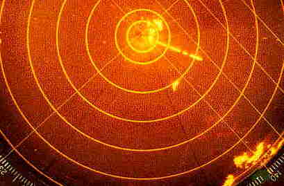
[edit]

When a racon receives a radar pulse, it responds with a signal on the same frequency which puts an image on the radar display. This takes the form of a short line of dots and dashes forming a Morse character radiating away from the location of the beacon on the normal plan position indicator radar display. The length of the line usually corresponds to the equivalent of a few nautical miles on the display.

Within the United States, the United States Coast Guard operates about 80 racons, and other organisations also operate them, for example the owners of oil platforms. Their use for purposes other than aids to navigation is prohibited, and they are used to mark:

In other parts of the world they are also used to indicate:

  • temporary, new and uncharted hazards (with a Morse character "D")
  • as leading line racons
A United States Coast Guard technician prepares a racon for installation at Fowey Rocks Light southeast of Miami.

Their characteristics are defined in the ITU-R Recommendation M.824, Technical Parameters of Radar Beacons (RACONS). Racons usually operate on the 9320 MHz to 9500 MHz marine radar band (X-band), and most also operate on the 2920 MHz to 3100 MHz marine radar band (S-band). Modern racons are frequency-agile; they have a wide-band receiver that detects the incoming radar pulse, tunes the transmitter and responds with a 25 microsecond long signal within 700 nanoseconds.

Older racons operate in a slow sweep mode, in which the transponder sweeps across the X-band over 1 or 2 minutes. It only responds if it happens to be tuned to the frequency of an incoming radar signal at the moment it arrives, which in practice means it responds only around 5% of the time.

To avoid the response masking important radar targets behind the beacon, racons only operate for part of the time. In the United Kingdom, a duty cycle of about 30% is used — usually 20 seconds in which the racon will respond to radar signals is followed by 40 seconds when it will not, or sometimes 9 seconds on and 21 seconds off (as in the case of the Sevenstones Lightship). In the United States a longer duty cycle is used, 50% for battery-powered buoys (20 seconds on, 20 seconds off) and 75% for on-shore beacons.

Ramarks are wide-band beacons which transmit continuously on the radar bands without having to be triggered by an incoming radar signal. The transmission forms a line of Morse characters on the display radiating from the centre of the display to its edge. They are not used in the United States.

Enhanced RACON

[edit]

Enhanced RACON (or e-RACON) is a proposal for introducing unique identification to the radar response of a RACON, enabling enhanced RADAR positioning.

This proposal is currently being brought forward to the maritime industry by the Danish Maritime Safety Administration through IALA. The recommendations[7] and performance requirements[8] for RACON are under consideration for revision, due to issues of limited ability to trigger RACON responses introduced by New Technology (NT) Radar.

An opportunity for practical testing of the concept in 2011 is being considered in the EfficienSea project,[9] partly financed by the Baltic Sea Region Programme[10] and coordinated by the Danish Maritime Safety Administration.

Principle

[edit]

When a traditional RACON receives a radar pulse, it responds with a signal which on a radar screen takes the form of a short line of dashes and dots forming a Morse character radiating away from the location of the beacon. Typically, the Morse character starts with a dash – a long, continuous signal.

The proposal for Enhanced RACON is to further modulate this first dash, with a small amount of digital information to enable either the unique identification of this particular RACON (for instance 30 bits of data identifying the RACON by a MMSI) or alternatively to identify the position of the RACON.

Introducing a unique identification would enable enhanced RADAR positioning through the ability to correlate the radar response of a RACON with the known position of that RACON. This could either be derived from an associated AIS signal representing the same object with the same identifier, or potentially in the future from information contained in a nautical publication, such as an electronic navigational chart in the emerging S-100 format.

See also

[edit]

References

[edit]
[edit]
Revisions and contributorsEdit on WikipediaRead on Wikipedia
from Grokipedia
A radar beacon, also known as a racon, is a receiver-transmitter device employed as a maritime that automatically responds to interrogating pulses by transmitting a narrow-band, Morse code-encoded signal, which appears as a distinctive mark on the radar display to precisely identify the location of buoys, landmarks, hazards, or other fixed points. These devices operate primarily in the X-band (9300-9500 MHz) and S-band (2900-3100 MHz) frequencies, with a typical response delay of less than 700 nanoseconds and a power output of around 600 mW, enabling a detection range of approximately 15 nautical miles. Developed during World War II as an evolution of identification friend-or-foe (IFF) systems to enhance navigation and targeting accuracy, radar beacons were initially deployed for military applications such as aircraft and ship positioning before transitioning to civilian maritime use. In modern applications, they are standardized by international bodies like the International Association of Marine Aids to Navigation and Lighthouse Authorities (IALA) and the International Telecommunication Union (ITU), with the United States Coast Guard maintaining about 80 such systems to mark coastlines, bridges, oil platforms, and sensitive areas, often using a 50% duty cycle for buoy-mounted units and up to 75% for shore-based ones. Radar beacons improve safety by providing unambiguous identification in poor visibility, distinguishing fixed aids from natural echoes, and are integral to global radionavigation services as defined in ITU-R Recommendation M.824.

History and Development

Origins and Invention

The development of radar beacons emerged in the amid the urgent and identification challenges posed by , particularly for maritime and aerial operations where distinguishing friendly forces from adversaries was critical. British and American engineers, collaborating through wartime alliances, addressed these needs by building on early technologies. Initial concepts drew from British efforts at the Bawdsey Research Station under the , where systems were explored as early as 1939 to enhance coastal surveillance and air defense. The Telecommunications Research Establishment (TRE) further advanced these with the Rebecca-Eureka system in 1942–1943, a that influenced later marine applications. In the United States, the , established in 1940 under the (NDRC), accelerated microwave-based research starting in 1941, integrating British designs to support Allied interoperability. The basic radar beacon, known as RACON (Radar Beacon), evolved from wartime Identification Friend or Foe (IFF) technologies, such as the British IFF Mark III, with a focus on marine applications to aid convoy protection and harbor security. Early prototypes of the RACON were tested in 1945, operating in the I-band frequencies (around 9-10 GHz, corresponding to 3 cm wavelengths) to facilitate ship identification in cluttered coastal environments. These trials, including sea exercises in the , demonstrated the beacon's ability to produce distinctive Morse-coded signals on screens, extending effective detection ranges up to 20-50 miles under operational conditions. The prototypes incorporated compact magnetron transmitters and pulse-delay circuits to minimize response times, ensuring with interrogating s. By late 1945, refinements allowed for frequency agility to counter jamming, marking a pivotal step in wartime enhancement. Integration of radar beacons into Allied naval operations occurred by 1946, with the U.S. Navy deploying over 45 RACON stations across the Pacific and Atlantic theaters to support post-invasion and fleet maneuvers. These installations provided automated distance and bearing cues for approaching ships and , significantly improving navigational accuracy in or at night. The collaborative British-U.S. effort, documented in joint reports from the Radiation Laboratory, ensured standardized coding and frequencies, laying the groundwork for broader military adoption while transitioning from wartime secrecy to operational routine.

Evolution and Standardization

Following , radar beacons underwent significant refinements to enhance their reliability and integration into civilian maritime navigation. In the , early operational deployments focused on improving response accuracy and range, with international efforts beginning to standardize frequencies and coding to prevent interference. The (ITU) played a key role in these developments through radio regulations that allocated for aids, laying the groundwork for global harmonization. These efforts culminated in the (IMO) adopting Resolution A.423(XI) in 1979, which recommended performance standards for radar beacons and transponders to improve navigational safety, including specifications for signal coding and operational use in marine environments. The saw the introduction of S-band beacons operating in the 2900–3100 MHz range, offering superior performance in adverse weather conditions compared to X-band systems due to reduced from and . This advancement was driven by evolving technology and ITU spectrum allocations, enabling beacons to respond effectively to both S-band and X-band interrogations for broader compatibility. By the , enhancements emphasized automatic identification features, such as improved responses and selective triggering to minimize false activations, as outlined in preparatory work leading to IMO standards. These upgrades allowed beacons to provide more precise positional data, supporting automated navigation systems. In the , digital coding improvements refined signal modulation and error correction, enhancing beacon readability on modern radar displays amid increasing electromagnetic congestion. IMO Resolution A.615(15), adopted in 1987 but influencing subsequent revisions, specified operational parameters for these digital enhancements, including response timing and power levels to ensure . As of 2025, radar beacon standards under the Safety of Life at Sea (SOLAS) conventions integrate with the Automatic Identification System (AIS) as complementary electronic aids to navigation, as described in IMO e-navigation frameworks. SOLAS Chapter V, Regulation 19 mandates AIS on ships, while beacons like racons augment this by providing fixed-point radar responses that align with AIS data for enhanced in vessel traffic services. Current ITU-R Recommendation M.824 continues to define technical parameters, ensuring seamless operation alongside AIS in global maritime networks.

Principles of Operation

Basic Mechanism

A radar beacon, also known as a racon, operates as an active that detects incoming pulses from an interrogating system via a dedicated receiving antenna tuned to specific bands, such as the X-band (9,300–9,500 MHz) for maritime applications. Upon detection, the beacon's receiver circuit processes the , triggering the integrated transmitter to generate and retransmit a response signal, thereby enhancing the visibility of the beacon's location on the interrogating radar's display. The timing of the response is critical for accurate range determination, with the total round-trip propagation delay td=2Rct_d = \frac{2R}{c}, where RR is the from the interrogating to the and cc is the (approximately 3 × 10^8 m/s). This equation ensures the response aligns with the primary timing, as the introduces only a minimal delay, typically not exceeding 0.7 μs, to minimize range (on the order of 100 or less). The short delay allows the response to appear precisely at the 's range on the screen, facilitating reliable positioning without significant offset. Unlike reflectors, which simply redirect incident energy without amplification, radar beacons utilize active receiver-transmitter circuits to amplify the detected signal and retransmit it at higher power, improving detection range and signal strength in adverse conditions. This active amplification enables the beacon to serve as a reliable aid, particularly in cluttered environments. The response signal is non-coherent, meaning it does not maintain phase with the original interrogating pulse, which prevents constructive or destructive interference with the echoes from the beacon's physical structure or nearby objects. This non-coherent nature allows the response to be distinctly identifiable while coexisting with natural returns on the .

Signal Response and Coding

Radar beacons, or RACONs, generate responses consisting of coded pulse trains that provide unique identification to interrogating radars. The primary response type employs a series of pulses modulated to form Morse code sequences, typically representing one or more letters assigned to the beacon's location as per navigational standards. These sequences are encoded in a train of response pulses synchronized to the interrogator's pulse repetition frequency (PRF), where a dot is represented by a single pulse, a dash by three pulses, and intervals between elements by gaps of appropriate units (e.g., one unit within letters, three units between letters), ensuring the coding spans the full duration of the response for clear visibility on the radar display. In some applications, such as aeronautical RACONs, digital pulse codes may be used instead, consisting of fixed patterns like 15 predefined sequences for identification, though Morse remains the standard for maritime use. The coding is achieved through techniques, where the presence or absence of pulses encodes the information; specifically, on-off keying interrupts the pulse stream to create the Morse pattern without altering the carrier . may be applied in user-selectable variants, such as with a 25 MHz modulation and near-unity index to produce sidebands for enhanced response agility, but standard RACONs rely on precise pulse timing for encoding. This approach ensures compatibility with interrogating frequencies in the X- or S-bands, with the response matched to within ±3.5 MHz of the incoming signal. To synchronize the response with the radar's scanning pattern and avoid range ambiguities, the beacon's aligns with that of the interrogator, expressed as PRFresp=PRFinterPRF_{resp} = PRF_{inter}. This matching allows the RACON to trigger a response for each received , positioning the coded signal accurately along the radar's range scale after accounting for delay, typically ≤0.7 µs. Error handling in RACON signals incorporates built-in through extended response durations, often equivalent to 20% of the radar's maximum range or up to 5 nautical miles, which repeats the coded train multiple times during the antenna beam's dwell period. This repetition mitigates signal loss in noisy or cluttered environments by increasing the probability of detection, as the prolonged transmission overcomes intermittent interference or weak receptions. Additionally, sidelobe suppression circuits prevent false triggering from radar side lobes, further enhancing reliability by limiting responses to main beam interrogations.

Types of Radar Beacons

Standard RACON

The standard RACON, or , refers to the conventional general-purpose maritime type, defined in international standards as providing an omnidirectional response pattern covering 360 degrees in to interrogating shipborne radars. This aligns with performance requirements outlined in IMO Resolution A.615(15), emphasizing reliable identification of navigational aids without directional limitations. General-purpose RACONs transmit a signal, typically a single letter or numeral, upon detection of a radar , ensuring clear bearing and range information on the interrogating radar's display. Other variants include user-selectable sector responses and aeronautical fixed-frequency applications, but the general-purpose type remains the baseline for broad maritime use. Operationally, standard RACONs function in the X-band frequency range of 9,300 to 9,500 MHz, with primary emphasis on 9 GHz to match common systems, enabling compatibility with horizontal polarization radars. The typical effective range extends from 20 to 40 nautical miles, influenced by factors such as antenna height, transmitted power (approximately 600 mW (0.6 W) radiated power), and line-of-sight conditions, though actual performance may vary with environmental . This range supports identification of fixed aids to from sufficient distances for safe maneuvering, with the response signal appearing as an extended spike or line on the screen, starting from the beacon's position outward. One key advantage of the standard RACON is its simplicity and cost-effectiveness, requiring minimal for installation on fixed sites like lighthouses, , or prominent headlands, where it provides unambiguous visual confirmation of without complex . These devices have been widely adopted since the mid-20th century for their reliability in poor visibility, offering a passive yet responsive aid that enhances at a fraction of the cost of more advanced systems. Despite these benefits, standard RACONs have notable limitations, including high susceptibility to sea clutter, where radar returns from ocean waves can mask or degrade the beacon's signal, particularly in rough conditions or when anti-clutter controls on the interrogating are activated. Additionally, as analog systems, they lack integration with digital navigation frameworks like AIS or GPS, limiting their utility in modern e-navigation environments without supplementary equipment. The core response relies on basic pulse detection and modulated transmission, as detailed in operational principles.

Enhanced and Specialized Variants

The Enhanced RACON (eRacon), introduced in the early as part of the Enhanced Radar Positioning System (ERPS), represents a digital evolution of traditional beacons designed to provide precise, GNSS-independent positioning for maritime navigation. Unlike conventional analog systems, eRacons employ digital encoding of absolute position within their response signals, enabling shipboard s equipped with compatible eRadar to perform automatic and compute vessel positions with accuracy comparable to unaugmented GNSS, typically within 10-20 meters under optimal conditions. This digital coding minimizes response ambiguity by embedding unique identifiers and coordinates, addressing limitations in cluttered displays. Development trials, such as those conducted in in October 2011 and at port in 2013-2017, demonstrated feasibility for port and harbor environments, with systems leveraging cost-effective for retrofitting existing beacons. As of 2025, eRacon systems are still in development and trial phases, with limited operational deployment. These enhancements align with () requirements under Resolution A.615(15) for beacons to support safe navigation, particularly in areas prone to GNSS vulnerabilities like jamming or multipath interference. Specialized variants of radar beacons extend functionality to niche operational domains. The S-band RAMARK, a continuous-transmitting radar marker operating in the 10 cm (S) wavelength band (2-4 GHz), was tailored for applications, providing reliable homing signals for radar systems in low-visibility conditions or over water. Deployed since the mid-20th century, ramarks are no longer in operational use. In maritime contexts, (AIS) aids to use Message 21 to broadcast status and position data via VHF, complementing beacons by providing digital vessel tracking separate from radar responses. These systems facilitate enhanced in vessel services by allowing remote monitoring of health (e.g., operational status). Key improvements in these variants focus on reliability and . Selective protocols in enhanced systems, such as Mode S-inspired addressing in aviation-compatible beacons, reduce false responses by limiting replies to authorized interrogators, mitigating issues like (False Replies Unsynchronized In Time) in dense environments. This is achieved through encoded digital replies that verify interrogator identity before transmission, significantly lowering clutter compared to omnidirectional analog responses. Furthermore, integration with systems like GNSS positions eRacons as complementary aids, offering absolute positioning redundancy during outages; for instance, ERPS triangulates vessel location using multiple eRacon signals when GNSS signals are degraded, ensuring continuity in critical . Such approaches have been validated in field tests, showing improved availability in GNSS-denied areas like urban harbors or conflict zones.

Applications and Uses

Maritime and Navigation

Radar beacons, commonly known as RACONs, play a critical role in maritime navigation by marking navigational hazards such as reefs, wrecks, and isolated dangers, as well as buoys and other aids to . When interrogated by a ship's , these devices transmit a coded response—typically in —that appears as an elongated echo on the , providing unambiguous identification even in conditions of poor visibility like or darkness. This functionality supports collision avoidance in accordance with Rule 7 of the International Regulations for Preventing Collisions at Sea (COLREGS), which requires vessels to use all available means, including , to determine if a risk of collision exists. Integration with the Electronic Chart Display and Information System (ECDIS) further enhances their utility, as RACON signals can be overlaid onto electronic nautical charts, enabling mariners to verify the position of hazards against charted data in real-time. This overlay capability allows for precise correlation between radar-detected responses and digital chart features, reducing the risk of misinterpretation and improving overall during voyage planning and execution. Such integration is particularly valuable in dynamic environments where traditional visual aids may be obscured, ensuring compliance with navigation safety standards. In practical deployments, RACONs are commonly installed on offshore oil rigs to delineate these high-risk structures, where explosion-proof models are employed to withstand hazardous conditions while providing reliable identification for approaching vessels. Similarly, at port entrances like those in major harbors, RACONs mark leading lines and turning points, facilitating safe ingress and egress. The widespread adoption of radar beacons in maritime applications gained momentum in the 1970s. These events influenced the International Maritime Organization (IMO) to issue Resolution A.423(XI) in 1979, recommending the strategic placement of RACONs to enhance safety in critical areas. Under the International Convention for the Safety of Life at Sea (SOLAS) Chapter V, Regulation 13, contracting governments are obligated to establish and maintain aids to navigation in locations deemed necessary for safe passage.

Aviation and Air Traffic Control

In aviation, radar beacons play a crucial role in augmenting Very High Frequency Omnidirectional Range (VOR) systems through Distance Measuring Equipment (DME), which provides pilots with precise slant-range distances to ground-based transponder stations for en-route navigation. These ground-based DME beacons respond to aircraft interrogations on UHF frequencies, enabling accurate positioning when combined with VOR bearing information, thus supporting efficient routing over long distances. Ground-based beacons, such as those integrated with VOR/DME facilities at airports, also aid in runway identification during terminal phases by confirming distances to key approach points. The Radar Beacon System (ATCRBS), a form of , further integrates radar beacon technology by equipping aircraft with that reply to ground interrogators, displaying unique identification codes and altitude data on controller screens for enhanced tracking. Adopted by the (FAA) in the 1960s following Project Beacon recommendations, ATCRBS expanded to 20 operational sites across 16 Air Route Traffic Control Centers (ARTCCs) by May 1960, revolutionizing terminal radar capabilities for safer aircraft separation. Post-9/11 security measures included mandatory transponder usage in additional and upgrades to Mode S protocols, improving identification to prevent unauthorized intrusions. Military adaptations extend radar beacon principles through Identification Friend or Foe (IFF) systems, where aircraft transponders respond to radar interrogations with coded signals to distinguish friendly forces in contested airspace. IFF modes, evolving from World War II-era designs, share operational similarities with civil ATCRBS but incorporate encryption for secure military applications. These systems collectively enhance in low-visibility conditions by providing reliable, non-cooperative-independent returns that penetrate weather and clutter, reducing collision risks during instrument approaches. Enhanced variants, such as Mode S, further refine these capabilities with selective addressing to minimize interference in dense air traffic.

Technical Aspects and Implementation

Frequency Bands and Power Requirements

Radar beacons, commonly known as racons, primarily operate within two microwave frequency bands designated by the (ITU) for maritime radionavigation: the S-band (2.9 to 3.1 GHz) and the X-band (9.3 to 9.5 GHz). The S-band supports longer detection ranges with reduced in adverse weather conditions such as rain or fog, making it suitable for open-sea applications. In contrast, the X-band provides superior thanks to its shorter wavelength, enabling precise bearing for close-range identification of navigational aids. Power requirements for racons emphasize energy efficiency and minimal interference, particularly for installations on buoys or remote sites. Modern solid-state designs typically feature peak transmit powers of 0.5 to 1 , with average power consumption limited to a few hundred milliwatts through duty cycles of 50% for buoy-mounted units and up to 75% for shore-based ones. These parameters ensure reliable responses without overwhelming the interrogating radar's display, as duty cycles are capped to prevent masking of genuine targets; for instance, response durations are limited to approximately 20% of the expected maximum range or 5 nautical miles, whichever is shorter. The effective detection range of a radar beacon, typically around 15 nautical miles, is influenced by factors including the radar range equation, which can be adapted to quantify the maximum distance RmaxR_{max} at which the interrogating radar can trigger and receive the beacon's response: Rmax=(PtGtGrλ2σ(4π)3Smin)1/4R_{max} = \left( \frac{P_t G_t G_r \lambda^2 \sigma}{(4\pi)^3 S_{min}} \right)^{1/4} Here, PtP_t represents the peak transmit power of the interrogating radar (typically 4 to 25 kW for marine systems), GtG_t and GrG_r are the gains of the radar's transmit and receive antennas, λ\lambda is the operating wavelength, σ\sigma is the beacon's effective radar cross-section enhanced by its amplified response, and SminS_{min} is the radar receiver's minimum detectable signal threshold. This equation highlights how beacon performance scales with radar power and frequency, with X-band systems achieving sharper ranges compared to S-band. To mitigate interference, racons employ band-specific filtering aligned with ITU allocations, rejecting signals outside the designated S- and X-band channels to avoid disrupting adjacent radionavigation or communication services. Frequency-agile designs further enhance compliance by automatically tuning to the interrogating radar's frequency within the allocated band, ensuring selective response without spurious emissions.

Installation and Maintenance

Site selection for radar beacons prioritizes elevated and unobstructed positions to maximize line-of-sight coverage and ensure reliable signal over marine areas, typically aiming for heights that minimize or structural interference. In marine environments, installations must incorporate robust weatherproofing measures, such as corrosion-resistant enclosures and sealed components, to withstand exposure to saltwater spray, high humidity, and conditions. These considerations align with international standards for aids to , including hazardous area certifications like ATEX or IECEx for offshore sites, where fixed structures like lighthouses or offshore platforms provide ideal mounting points for optimal performance. The setup process begins with mechanical mounting of the antenna unit, ensuring secure fixation to the selected site using appropriate brackets or masts compatible with the environment. Antenna alignment follows, involving precise orientation to align the beam pattern with expected interrogation paths, often verified through initial signal tests. Power supply integration connects the beacon to reliable sources, such as grid electricity for shore-based units or solar panels with battery backups for remote marine locations, meeting low-voltage DC requirements typically between 12V and 24V. Final tests, conducted via diagnostic terminals or software interfaces, adjust response coding, sensitivity, and output to confirm operational integrity before commissioning. Maintenance protocols emphasize preventive measures to sustain reliability, including annual inspections that encompass visual examinations of physical components, of response signals, and verification of power systems as recommended by (IMO) and International Association of Marine Aids to Navigation and Lighthouse Authorities (IALA) guidelines for aids to navigation. Troubleshooting for signal degradation involves checking for faults in the receiver-transmitter chain, antenna integrity, or power fluctuations, often using onboard status displays or remote monitoring tools to identify issues like intermittent responses. These routines ensure , with minimal ongoing intervention required post-installation for well-designed systems. Key challenges in radar beacon deployment include from prolonged saltwater exposure, which can degrade metal housings and electrical connections, necessitating regular application of protective coatings and periodic component replacements. Modern digital and frequency-agile variants require periodic updates to enhance compatibility with evolving systems and spectrum regulations, often through remote or on-site programming.

References

Add your contribution
Related Hubs
User Avatar
No comments yet.