
Community hub
Recent from talks
Contribute something
Nothing was collected or created yet.
Scene graph
View on Wikipedia
A scene graph is a general data structure commonly used by vector-based graphics editing applications and modern computer games, which arranges the logical and often spatial representation of a graphical scene. It is a collection of nodes in a graph or tree structure. A tree node may have many children but only a single parent, with the effect of a parent applied to all its child nodes; an operation performed on a group automatically propagates its effect to all of its members. In many programs, associating a geometrical transformation matrix (see also transformation and matrix) at each group level and concatenating such matrices together is an efficient and natural way to process such operations. A common feature, for instance, is the ability to group related shapes and objects into a compound object that can then be manipulated as easily as a single object.
In graphics editing tools
[edit]In vector-based graphics editing, each leaf node in a scene graph represents some atomic unit of the document, usually a shape such as an ellipse or Bezier path. Although shapes themselves (particularly paths) can be decomposed further into nodes such as spline nodes, it is practical to think of the scene graph as composed of shapes rather than going to a lower level of representation.
Another useful and user-driven node concept is the layer. A layer acts like a transparent sheet upon which any number of shapes and shape groups can be placed. The document then becomes a set of layers, any of which can be conveniently made invisible, dimmed, or locked (made read-only). Some applications place all layers in a linear list, while others support layers within layers to any desired depth.
Internally, there may be no real structural difference between layers and groups at all, since they are both just nodes of a scene graph. If differences are needed, a common type declaration in C++ would be to make a generic node class, and then derive layers and groups as subclasses. A visibility member, for example, would be a feature of a layer, but not necessarily of a group.
In games and 3D applications
[edit]Scene graphs are useful for modern games using 3D graphics and increasingly large worlds or levels. In such applications, nodes in a scene graph (generally) represent entities or objects in the scene.
For instance, a game might define a logical relationship between a knight and a horse so that the knight is considered an extension to the horse. The scene graph would have a 'horse' node with a 'knight' node attached to it.
The scene graph may also describe the spatial, as well as the logical, relationship of the various entities: the knight moves through 3D space as the horse moves.
In these large applications, memory requirements are major considerations when designing a scene graph. For this reason, many large scene graph systems use geometry instancing to reduce memory costs and increase speed. In our example above, each knight is a separate scene node, but the graphical representation of the knight (made up of a 3D mesh, textures, materials and shaders) is instanced. This means that only a single copy of the data is kept, which is then referenced by any 'knight' nodes in the scene graph. This allows a reduced memory budget and increased speed, since when a new knight node is created, the appearance data need not be duplicated.
Implementation
[edit]The simplest form of scene graph uses an array or linked list data structure, and displaying its shapes is simply a matter of linearly iterating the nodes one by one. Other common operations, such as checking to see which shape intersects the mouse pointer are also done via linear searches. For small scene graphs, this tends to suffice.
Operations and dispatch
[edit]Applying an operation on a scene graph requires some way of dispatching an operation based on a node's type. For example, in a render operation, a transformation group node would accumulate its transformation by matrix multiplication, vector displacement, quaternions or Euler angles. After which a leaf node sends the object off for rendering to the renderer. Some implementations might render the object directly, which invokes the underlying rendering API, such as DirectX or OpenGL. But since the underlying implementation of the rendering API usually lacks portability, one might separate the scene graph and rendering systems instead. In order to accomplish this type of dispatching, several different approaches can be taken.
In object-oriented languages such as C++, this can easily be achieved by virtual functions, where each represents an operation that can be performed on a node. Virtual functions are simple to write, but it is usually impossible to add new operations to nodes without access to the source code. Alternatively, the visitor pattern can be used. This has a similar disadvantage in that it is similarly difficult to add new node types.
Other techniques involve the use of RTTI (Run-Time Type Information). The operation can be realised as a class that is passed to the current node; it then queries the node's type using RTTI and looks up the correct operation in an array of callbacks or functors. This requires that the map of types to callbacks or functors be initialized at runtime, but offers more flexibility, speed and extensibility.
Variations on these techniques exist, and new methods can offer added benefits. One alternative is scene graph rebuilding, where the scene graph is rebuilt for each of the operations performed. This, however, can be very slow, but produces a highly optimised scene graph. It demonstrates that a good scene graph implementation depends heavily on the application in which it is used.
Traversals
[edit]Traversals are the key to the power of applying operations to scene graphs. A traversal generally consists of starting at some arbitrary node (often the root of the scene graph), applying the operation(s) (often the updating and rendering operations are applied one after the other), and recursively moving down the scene graph (tree) to the child nodes, until a leaf node is reached. At this point, many scene graph engines then traverse back up the tree, applying a similar operation. For example, consider a render operation that takes transformations into account: while recursively traversing down the scene graph hierarchy, a pre-render operation is called. If the node is a transformation node, it adds its own transformation to the current transformation matrix. Once the operation finishes traversing all the children of a node, it calls the node's post-render operation so that the transformation node can undo the transformation. This approach drastically reduces the necessary amount of matrix multiplication.[citation needed]
Some scene graph operations are actually more efficient when nodes are traversed in a different order – this is where some systems implement scene graph rebuilding to reorder the scene graph into an easier-to-parse format or tree.
For example, in 2D cases, scene graphs typically render themselves by starting at the tree's root node and then recursively draw the child nodes. The tree's leaves represent the most foreground objects. Since drawing proceeds from back to front with closer objects simply overwriting farther ones, the process is known as employing the Painter's algorithm. In 3D systems, which often employ depth buffers, it is more efficient to draw the closest objects first, since farther objects often need only be depth-tested instead of actually rendered, because they are occluded by nearer objects.
Scene graphs and bounding volume hierarchies (BVHs)
[edit]Bounding Volume Hierarchies (BVHs) are useful for numerous tasks – including efficient culling and speeding up collision detection between objects. A BVH is a spatial structure, but doesn't have to partition the geometry (see spatial partitioning below).
A BVH is a tree of bounding volumes (often spheres, axis-aligned bounding boxes or oriented bounding boxes). At the bottom of the hierarchy, the size of the volume is just large enough to encompass a single object tightly (or possibly even some smaller fraction of an object in high resolution BVHs). As one ascends the hierarchy, each node has its own volume that tightly encompasses all the volumes beneath it. At the root of the tree is a volume that encompasses all the volumes in the tree (the whole scene).
BVHs are useful for speeding up collision detection between objects. If an object's bounding volume does not intersect a volume higher in the tree, it cannot intersect any object below that node (so they are all rejected very quickly).
There are some similarities between BVHs and scene graphs. A scene graph can easily be adapted to include/become a BVH – if each node has a volume associated or there is a purpose-built "bound node" added in at convenient location in the hierarchy. This may not be the typical view of a scene graph, but there are benefits to including a BVH in a scene graph.
Scene graphs and spatial partitioning
[edit]An effective way of combining spatial partitioning and scene graphs is by creating a scene leaf node that contains the spatial partitioning data.[clarification needed] This can increase computational efficiency of rendering.
Spatial data is usually static and generally contains non-moving scene data in some partitioned form.[clarification needed] Some systems may have the systems and their rendering separately. This is fine and there are no real advantages to either method. In particular, it is bad to have the scene graph contained within the spatial partitioning system, as the scene graph is better thought of as the grander system to the spatial partitioning.[neutrality is disputed]
Very large drawings, or scene graphs that are generated solely at runtime (as happens in ray tracing rendering programs), require defining of group nodes in a more automated fashion. A raytracer, for example, will take a scene description of a 3D model and build an internal representation that breaks up its individual parts into bounding boxes (also called bounding slabs). These boxes are grouped hierarchically so that ray intersection tests (as part of visibility determination) can be efficiently computed. A group box that does not intersect an eye ray, for example, can entirely skip testing any of its members.
A similar efficiency holds in 2D applications as well. If the user has magnified a document so that only part of it is visible on their computer screen, and then scrolls in it, it is useful to use a bounding box (or in this case, a bounding rectangle scheme) to quickly determine which scene graph elements are visible and thus actually need to be drawn.
Depending on the particulars of the application's drawing performance, a large part of the scene graph's design can be impacted by rendering efficiency considerations. In 3D video games such as Quake, binary space partitioning (BSP) trees are heavily favored to minimize visibility tests. BSP trees, however, take a very long time to compute from design scene graphs, and must be recomputed if the design scene graph changes, so the levels tend to remain static, and dynamic characters aren't generally considered in the spatial partitioning scheme.
Scene graphs for dense regular objects such as heightfields and polygon meshes tend to employ quadtrees and octrees, which are specialized variants of a 3D bounding box hierarchy. Since a heightfield occupies a box volume itself, recursively subdividing this box into eight subboxes (hence the 'oct' in octree) until individual heightfield elements are reached is efficient and natural. A quadtree is simply a 2D octree.
Standards
[edit]PHIGS
[edit]PHIGS was the first commercial scene graph specification, and became an ANSI standard in 1988. Disparate implementations were provided by Unix hardware vendors. The HOOPS 3D Graphics System appears to have been the first commercial scene graph library provided by a single software vendor. It was designed to run on disparate lower-level 2D and 3D interfaces, with the first major production version (v3.0) completed in 1991.
SGI
[edit]Silicon Graphics (SGI) released OpenGL Performer or more commonly called Performer in 1991 which was the primary scenegraph system for most SGI products into the future. IRIS Inventor 1.0 (1992) was released by SGI, which was a high level scene graph built on top of Performer. It was followed up with Open Inventor in 1994, another iteration of the high level scene graph built on top of newer releases of Performer. More 3D scene graph libraries can be found in Category:3D scenegraph APIs.
X3D
[edit]X3D is a royalty-free open standards file format and run-time architecture to represent and communicate 3D scenes and objects using XML. It is an ISO-ratified standard that provides a system for the storage, retrieval and playback of real-time graphics content embedded in applications, all within an open architecture to support a wide array of domains and user scenarios.
See also
[edit]References
[edit]This article includes a list of references, related reading, or external links, but its sources remain unclear because it lacks inline citations. (December 2014) |
Books
[edit]- Leler, Wm and Merry, Jim (1996) 3D with HOOPS, Addison-Wesley
- Wernecke, Josie (1994) The Inventor Mentor: Programming Object-Oriented 3D Graphics with Open Inventor, Addison-Wesley, ISBN 0-201-62495-8 (Release 2)
Articles
[edit]- Bar-Zeev, Avi. "Scenegraphs: Past, Present, and Future"
- Carey, Rikk and Bell, Gavin (1997). "The Annotated VRML 97 Reference Manual"
- James H. Clark (1976). "Hierarchical Geometric Models for Visible Surface Algorithms". Communications of the ACM. 19 (10): 547–554. doi:10.1145/360349.360354.
- Helman, Jim; Rohlf, John (1994). "IRIS Performer: A High Performance Multiprocessing Toolkit for Real-Time 3D Graphics"
- PEXTimes – "Unofficially, the PHIGS Extension to X. Officially, PEX was not an acronym."
- Strauss, Paul (1993). "IRIS Inventor, a 3D Graphics Toolkit"
External links
[edit]Scene graph
View on GrokipediaFundamentals
Definition and Core Concepts
A scene graph is a directed acyclic graph (DAG) or tree-like data structure commonly employed in computer graphics to represent and manage the elements of a 3D scene, with nodes denoting components such as geometry, lights, cameras, and transformations.[1][2] This structure establishes hierarchical relationships among scene elements, enabling the definition of spatial arrangements and dependencies in a modular fashion.[4] The core purposes of a scene graph revolve around facilitating efficient organization and manipulation of complex scenes for tasks like rendering, animation, and interactive applications, while inherently supporting hierarchical transformations that propagate changes through parent-child relationships and techniques such as view frustum culling to optimize computational resources.[5][6][7] By structuring data hierarchically, it allows developers to handle scene updates and traversals more effectively than non-hierarchical approaches, promoting reusability and performance in graphics pipelines.[8] A basic example of a scene graph is a simple tree where a root node serves as the top-level container, branching to transformation nodes that apply scaling, rotation, or translation to subgroups, and terminating in leaf nodes representing geometry such as meshes or primitives.[4][2] This setup illustrates how the graph encapsulates the entire scene description in a traversable form. Compared to flat lists of scene elements, scene graphs offer key advantages, including reduced data redundancy through shared subgraphs in DAG configurations—where identical substructures can be referenced multiple times without duplication—and simplified management of intricate, hierarchical scenes that involve nested objects and behaviors.[1][9]Node Types and Transformations
Scene graphs organize scene elements through a variety of node types, each serving specific roles in defining hierarchy, geometry, properties, and rendering behaviors. Group nodes act as containers to establish hierarchical relationships among other nodes, allowing complex scenes to be built by nesting substructures.[10] Transform nodes specify local changes in position, orientation, and scale, typically using 4x4 matrices for translation, rotation, and scaling operations.[10] Geometry nodes represent drawable primitives or meshes, such as spheres or polygons, which define the visual shapes in the scene.[10] Light nodes configure illumination sources, including parameters like intensity, color, and position for point, directional, or spot lights.[10] Camera nodes define viewpoints and projection settings, such as perspective or orthographic views, to determine how the scene is observed.[11] Switch nodes enable conditional rendering by selecting which child nodes to include or exclude based on an index or state, facilitating dynamic scene management.[12] Transformations in a scene graph propagate hierarchically from parent to child nodes, converting local coordinates to world coordinates through successive matrix operations. Each node's local transformation matrix is combined with its parent's world transformation via matrix multiplication to yield the child's world transformation: This process accumulates along the path from the root, ensuring that child elements inherit and compose transformations relative to their ancestors.[13] To optimize memory and performance, scene graphs often employ directed acyclic graphs (DAGs) for handling shared subgraphs, allowing multiple parents to reference the same child subgraph without duplication. This instancing mechanism supports efficient reuse of complex elements, such as repeated models in a scene.[1][14] For instance, in a character model, an arm subgraph—comprising geometry and transform nodes—attaches as a child to the body node; the arm's local rotation inherits the body's world position, enabling coordinated movement through hierarchical propagation.[3]History and Evolution
Origins in Early Graphics Systems
The concept of hierarchical structures in computer graphics, a foundational element of scene graphs, traces its origins to Ivan Sutherland's Sketchpad system developed in 1963 at MIT. Sketchpad introduced a mechanism for organizing drawings through "master drawings" and "instances," where subpictures defined in a master could be reused and instantiated multiple times, connected via pointers to ensure changes in the master propagated to all instances. This hierarchical approach allowed transformations like scaling and rotation to be applied at any level, enabling efficient manipulation and display of complex compositions, serving as a conceptual precursor to modern scene graphs.[15] Early standardization efforts in the 1970s built on these ideas through the Graphics Standards Planning Committee (GSPC) of ACM SIGGRAPH. The CORE system, outlined in the GSPC's 1977 status report, proposed a device-independent 3D graphics package emphasizing display lists for retaining and replaying graphical primitives, facilitating more structured scene management over purely immediate-mode rendering. Although the 1977 CORE excluded full hierarchical display lists—influenced by earlier systems like GPGS at Brown University, which supported such hierarchies—the GSPC's ongoing work by 1979 aimed to incorporate standardized hierarchical structures to handle complex scenes more effectively. These developments at universities, including pioneering graphics research at the University of North Carolina (UNC) and Stanford, further explored hierarchical modeling in experimental systems during the late 1970s.[16][17] A major milestone came in the 1980s with the Programmer's Hierarchical Interactive Graphics System (PHIGS), the first formal standard explicitly supporting scene graph-like structures for retained-mode graphics. Developed starting in 1984 and standardized by ISO in 1989 as ISO 9592, PHIGS introduced a "structure store" that organized graphical elements into editable hierarchies of primitives and transformations, allowing applications to build, traverse, and modify scenes independently of immediate rendering commands. This retained-mode paradigm shifted from the immediate-mode approaches of earlier systems, where graphics were drawn on-the-fly without persistent data structures, enabling better efficiency for interactive 3D applications.[17]Development in Modern Graphics APIs
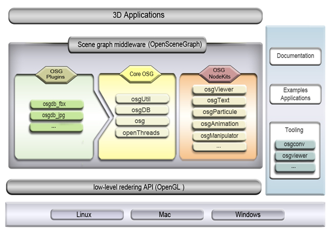
The development of scene graphs in modern graphics APIs began in the 1990s with Silicon Graphics Inc.'s (SGI) Open Inventor, the first commercial toolkit providing an object-oriented, retained-mode API for 3D graphics built initially on IRIS GL and subsequently ported to OpenGL.[18][19] This library abstracted complex graphics operations into a hierarchical structure of nodes, enabling developers to manage scenes more intuitively without direct manipulation of low-level drawing commands.[20] Building on this foundation, OpenSceneGraph was released in 1999 as an open-source C++ library, delivering high-performance scene graph capabilities optimized for real-time rendering in domains like visual simulations, scientific visualization, and games.[21] It extended the scene graph paradigm by supporting cross-platform deployment and efficient traversal for large-scale scenes, becoming a staple in professional applications requiring robust 3D management.[22] Scene graphs evolved to abstract calls to underlying APIs such as OpenGL and DirectX, facilitating portability and simplifying development in game engines. Unity, for example, incorporates an internal scene graph as a hierarchical data structure to organize 3D objects, transformations, and rendering across backends like OpenGL, DirectX, and Vulkan.[5][23] Likewise, Unreal Engine employs a scene graph-like hierarchy of actors and scene components to manage spatial relationships and abstract low-level rendering, supporting high-fidelity graphics via DirectX and other APIs.[24] By 2025, scene graphs have influenced web-based rendering through Three.js, a JavaScript library that structures WebGL scenes using a root Scene object and Object3D hierarchies to handle transformations and rendering efficiently in browsers.[25] In high-performance contexts, VulkanSceneGraph provides a modern C++ scene graph directly layered on Vulkan for cross-platform, GPU-accelerated applications demanding low overhead.[26] Similarly, Apple's SceneKit offers a high-level scene graph API built atop Metal, enabling optimized 3D rendering with features like physics integration and asset manipulation for iOS and macOS ecosystems.[27]Implementation
Data Structures and Operations
Scene graphs are typically implemented as directed acyclic graphs (DAGs), where nodes represent scene elements and directed edges denote parent-child relationships. The hierarchical structure is often stored using adjacency lists, with each node maintaining a list of pointers or handles to its child nodes, enabling efficient navigation of the parent-child links. For example, in Open Inventor, nodes are created with thenew operator and linked via pointers, while Java 3D employs a similar pointer-based system for connecting Group and Leaf nodes in the DAG. Memory management for dynamic scenes relies on handle-based references or smart pointers to track node lifetimes, particularly in resource-constrained environments where scenes evolve in real-time.
Core operations facilitate building and modifying the graph. Node creation involves instantiating objects via constructors or factory methods, such as new SoGroup() in Open Inventor or constructing Java 3D node instances. Deletion is handled automatically through reference counting, where a node's reference count decrements upon detachment, triggering deallocation when it reaches zero (e.g., via unref() in Open Inventor). Attachment and detachment use methods like addChild() and removeChild() to link or unlink subgraphs, preserving the DAG structure while updating parent pointers. Cloning subgraphs allows reuse without duplication, as seen in Java 3D's cloneTree() method, which supports options for deep copying or shared referencing to maintain efficiency. Update propagation for changes, such as transformations, occurs recursively from parents to children, ensuring consistent state across the hierarchy (e.g., via Update() calls in scene graph implementations).
Dispatch mechanisms route events through the hierarchy to handle user interactions. In standards like VRML and X3D, events are sent and received via nodes (e.g., TouchSensor), with routing defined by the graph structure to propagate actions like mouse clicks from leaves to ancestors. Java 3D employs Behavior nodes for dynamic event responses, dispatching updates based on the scene graph's traversal order during rendering.
Performance considerations emphasize efficient sharing of subgraphs to avoid redundancy. Reference counting for shared nodes, where a single node can have multiple parents in the DAG, prevents memory leaks by tracking usage across references—deletion only occurs when all parents release the node, as implemented in Open Inventor and implied in Java 3D's cloning flags. This approach minimizes memory overhead in complex scenes while supporting dynamic modifications without excessive copying.
Traversal Algorithms
Scene graph traversal algorithms enable systematic navigation of the hierarchical structure to execute operations such as rendering, querying, and optimization across nodes and their transformations. These algorithms typically process the graph starting from the root, applying accumulated state like transformation matrices to subtrees, and dispatching node-specific behaviors. Traversal is essential for efficiency in graphics pipelines, as it allows selective processing without redundant computations.[28][29] Common traversal types include depth-first and breadth-first approaches, with implementations varying between recursive and iterative methods. Depth-first traversal, often in pre-order (visiting the node before its children), is standard for rendering, as it mirrors the hierarchical application of transformations from parent to child, enabling immediate drawing of geometry after state updates. This involves recursively descending into subtrees left-to-right, maintaining a current transformation state updated as for each transformation node , then backtracking to restore prior states via a stack. Breadth-first traversal, processing nodes level-by-level using a queue, suits querying operations like finding all lights in the scene, as it avoids deep recursion in wide graphs. Recursive implementations leverage the call stack for simplicity but risk overflow in deep hierarchies; iterative versions use explicit stacks or queues for control and scalability in large scenes.[28][3] Key algorithms include render traversal and pick traversal. In render traversal, the algorithm descends the graph depth-first, accumulating transformations to position geometry nodes correctly before issuing draw calls, such as via OpenGL commands in systems like Open Inventor. This ensures coherent state management, where properties like materials propagate down the hierarchy until overridden. Pick traversal, used for object selection, employs ray casting: a ray originating from the viewer (e.g., mouse position) intersects the scene graph by testing against transformed bounding volumes during depth-first descent, returning the closest hit node for interaction. This method computes intersections for relevant subgraphs, prioritizing efficiency by early termination on opaque hits.[30][31] Optimizations like frustum culling integrate directly into traversal to skip off-screen subgraphs, reducing draw calls and CPU load. During depth-first traversal, each node's bounding box in local coordinates is transformed to world space via , where is the accumulated transformation matrix, then tested against the view frustum planes; if no intersection, the entire subtree is culled. This hierarchical check propagates savings, as parent culling avoids child processing, and is applied in rendering actions to balance host and GPU workloads. In SGI Performer, such culling occurs viaopDrawAction::apply() with modes like view-frustum culling enabled.[32][33]
Traversal often employs the visitor pattern for flexible dispatch of operations like animation updates or rendering. In this design, a visitor object (e.g., an "action" in Open Inventor) traverses the graph, invoking polymorphic methods on each node type—such as updating bone matrices for skinned meshes—without altering the node classes. This separates algorithm from structure, allowing multiple visitors (e.g., one for animation, another for culling) to reuse the same traversal logic.[30][29]