
Community hub
Viewfinder
View on WikipediaThis article needs additional citations for verification. (March 2014) |

In photography, a viewfinder is a device on a camera that a photographer uses to determine exactly where the camera is pointed, and approximately how much of that view will be photographed. A viewfinder can be mechanical (indicating only direction and approximate view), with simple optical components, with precision optics and optical functions, or a digital accessory device used with digital cameras.
View camera
[edit]
These cameras had no separate viewfinder. The exact image (although upside-down and reversed left-right) was viewed on a ground glass installed either in a replaceable plateholder, or in a spring back where springs hold the ground glass at the focus plane until a photographic plateholder is slid in front of it. Spring backs usually had a flip-up cover protecting the ground glass. A black focusing cloth was used with larger models.
Mechanical finders
[edit]Later referred to as "sports finders", for many sports and newspaper applications optical viewfinders gave too small an image and were inconvenient to use for scenes that were changing rapidly. For these purposes a simple arrangement of two wire rectangles, a smaller one nearer the eye[citation needed] and a larger one further away, was used, without optics; the two rectangles were aligned so the smaller one was centered in the larger, and the larger rectangle would give an indication of what would be included. Cameras with sportsfinders usually had optical viewfinders also.
Simple optical viewfinders
[edit]A single divergent (plano-concave) lens, in front of a frame, when close to the eye, acts as a viewfinder. Adding a convergent (plano-convex) lens makes a very short reversed Galilean (upright image) telescope. For movie camera or others with changeable lenses, outline marks on one of the viewfinder lenses could show the different fields of view for the different camera lenses.
Waist level (reflecting) viewfinders
[edit]Simple reflecting viewfinders, known also as "brilliant finders", comprised a small forward-looking lens, a small mirror at 45° behind it, and a lens at the top; the user held the camera at waist level and looked down into the lens, where a small image could be seen. Such viewfinders were integrated into box cameras, and fitted to the side of folding cameras. These viewfinders were fitted to inexpensive cameras.
-
 Child's waist-view box camera
 -
 Mamiya 645 1000s waist level finder
 -
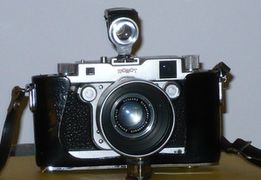 Robot Royal III camera with Zeiss Ikon waist level viewfinder attachment


Twin-lens reflex viewfinders
[edit]Twin-lens reflex (TLR) cameras use a viewfinding lens with the same focal length as the camera lens, so it has the same field of view and focus properties. With a mirror, of similar size to the film, held at 45°, it projects an upright image onto a focusing ground glass screen viewable from above. The camera can be then be held steady at waist level. Although the viewfinder lens was similar to the camera lens, the optical quality was less important and so the cost is reduced. TLR viewfinders do not have the interrupted viewing and shutter lag of the SLR type and so is preferred for dance photography.[2] Reinhold Heidecke cited his experience with periscope focusing from the German trenches in 1916 as the inspiration for the Rolleiflex line in 1929.[3] Some similar-looking cameras are actually simple box cameras with a waist-level viewfinder.
Single-lens reflex viewfinders
[edit]

Single-lens reflex (SLR) cameras use the camera lens itself, to completely eliminate parallax, the significant field-of-view error for close subjects caused by the offset distance between the viewfinder's lens and the camera's lens. Early SLRs were plate cameras, with a mechanism to insert a mirror between the lens and the film which reflected the light upwards, where it could be seen at waist level on a ground glass screen. When ready to take the picture, the mirror was pivoted out of the way (without moving the camera). Later SLR still cameras had a mechanism which flipped the mirror out of the way when the shutter button was pressed, opened and closed the shutter, and then moved the mirror back. The Zeiss Ikon Contax S was the first SLR camera to allow easy eye-level viewing by using a roof pentaprism to laterally reverse the inverted camera image (the reflex mirror had already vertically reversed the image).[citation needed] SLR movie cameras used a beamsplitter partial mirror to split the camera image between the shutter and film, and the viewfinder.[citation needed] A major advantage of SLR viewfinders is that any change of camera lens did not affect the viewing accuracy, and accurate camera focus did not depend on correct linking or calibration.
Rangefinders
[edit]Some sophisticated 20th century cameras with direct viewfinders had coincidence (split-image) rangefinders, initially with separate windows from the viewfinder, later integrated with it; they were called rangefinder cameras. Cameras with interchangeable lenses had to indicate the field of view of each lens in the viewfinder; more usually, interchangeable viewfinders to match the lenses were used.[4]
-
 Leica IIIf viewfinder camera, 1951
 -
 German Tewe 35 mm to 200 mm zoom viewfinder
 -
 Early 21st century digicam with viewfinder


Contemporary viewfinders
[edit]
Viewfinders can be optical or electronic. An optical viewfinder is simply a reversed telescope that displays what the camera sees. It has many drawbacks, but it also has advantages; it consumes no power, it does not wash out in sunlight, and it has "full resolution" (i.e. the resolution of the photographer's eye). Modern electronic viewfinders (EVF) are LCD or OLED based display devices. In addition to its primary purpose, an electronic viewfinder can be used to replay previously captured material, and as an on-screen display to browse through menus.
A still camera's optical viewfinder typically has one or more small supplementary LED displays surrounding the view of the scene. On a film camera, these displays show shooting information such as the shutter speed and aperture and, for autofocus cameras, provide an indication that the image is correctly focussed. Digital still cameras will typically also display information such as the current ISO setting and the number of remaining shots which can be taken in a burst. Another display which overlays the view of the scene is often provided. It typically shows the location and state of the camera's provided auto-focus points. This overlay can also provide lines or a grid which assist in picture composition.


It is not uncommon for a camera to have two viewfinders. For example, a digital still camera may have an optical viewfinder and an electronic one. The latter can be used to replay previously captured material, has an on-screen display, and can be switched off to save power. A camcorder may have two viewfinders, both electronic. The first is viewed through a magnifying eyepiece, and due to a rubber eyepiece it can be viewed perfectly even in bright light. The second viewfinder would be larger, of a higher resolution, and may be mounted on the side of the camera. Because it consumes more power, a method is often provided to turn it off to save energy.
In late 2010, Fujifilm announced hybrid viewfinder of optical viewfinder and electronic viewfinder in one viewfinder for its highend compact cameras. There is a half mirror prism that reflect data from LCD to the optical viewfinder, so we can see both the shooting frame and the shooting data. A button can change the hybrid function to electronical viewfinder by blocking the image through the optical viewfinder with moving a half mirror prism to be a straight up mirror.[5]
Viewfinders are used for virtually all cameras whether still or movie, film, electronic analog (Television) or digital. Many digital sensor cameras do not have a separate viewfinder. For those cameras, the electronic image is shown on a small accessory screen for composition and focusing purposes.[6] CCTVs and webcams do not need any viewfinding device.
See also
[edit]References
[edit]- ^ "Miniature Graphic". graflex.org. Retrieved 2019-12-11.
- ^ "Dance Movement Photography (DOC format)". arcaimaging.com. Retrieved 10 April 2018.
- ^ "Complete Collector's Guide to the Rollei TLR, Ian Parker, Hove Photo Books, Jersey, 1993
- ^ O'Neil, Daniel. "What is a Rangefinder Camera?".
- ^ "Fujifilm explains how its X100 hybrid viewfinder works, we nod and pretend to understand". Engadget. Retrieved November 2, 2013.
- ^ "Viewfinder Definition - What is a Viewfinder".